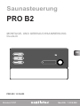
Sentiotec PRO-B2 Sauna Control PRO B Manuel utilisateur
- Taper
- Manuel utilisateur

Version 01/23 Ident-Nr. ST-M-00006-01
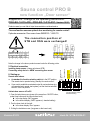
Sauna control PRO B
new function „Door sensor“
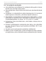
Supplement / change to the operating instructions:
PRO-B2 /1-015-455 , PRO-B3 /1-015-457 Version 12/21
Product manual you can nd at: https://www.sentiotec.com/downloads or
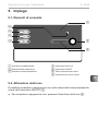
The new function ensures optimal door monitoring for remote control!
Optionale accessories: Door sensor home SAB00103 / 1-052-723
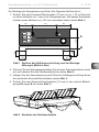
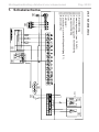
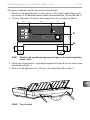
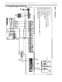
The connection position of
STB and OSG were exchanged!
Note the change in the above product manual under the following points:
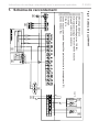
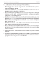
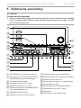
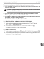
5. Electrical connection
Installing heater sensor (clamp red wires at STB)
Connecting safety device or NEW connecting door sensor
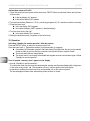
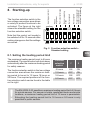
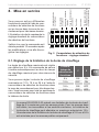
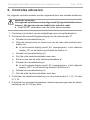
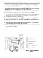
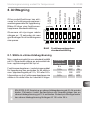
8. Starting up
Remote start release:
●As standard the function selection switch is in the OFF position.
The remote star is operated using „Standby for remote control“.
●If you want to enable the remote start output for various devices (e.g.
coinoperated unit, remote start system), set the function selection
switch 4 in the ON position
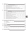
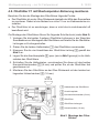
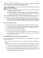
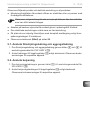
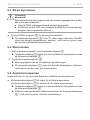
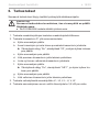
Activate door sensor at Pro B2
1. Open the technician menu (press at the same time: ON/OFF button,
preset time button and the lower bottom knob)
►In the top display „SdO“ appears
►In the bottom display „SAFE“ appears (= standard setting)
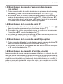
2. Turn the lower knob to the right
►In the lower display “door“ appears
3. Exiting the technician menu (Longpress on the lower knob)
EN
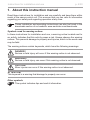
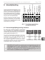
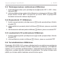
NEU
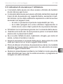
STB
Heating period
limit
Phase alignment
Remote start
release
Evaporator
single mode
Sensor operating
mode
Not assigned
Preset temperature /
Heater temperature
as actual emperature
OFF
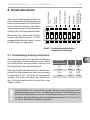
OSG
STBOSG
Function selection switch –
Standard setting
DE

EN
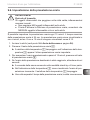
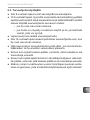
Additional sheet for instructions for use p. 2/2
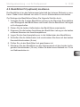
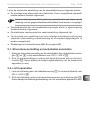
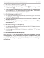
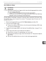
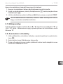
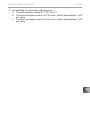
Activate door sensor at Pro B3
1. Open the technician menu (press at the same time: ON/OFF button, preset time button and the lower
bottom knob)
► In the top display „dry“ appears
► In the bottom display „t60“ appears
2. Turn the lower buttom (Selection 0 - 60; 0 = post-drying progamm off , 60 = maximum runtime in minutes)
3. Press the lower knob
►In the top display „SdO“ appears
►In the bottom display „SAFE“ appears (= standard setting)
4. Turn the lower knob to the right
►In the lower display “door“ appears
5. Exiting the technician menu (Longpress on the lower knob)
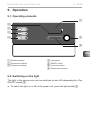
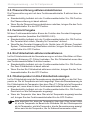
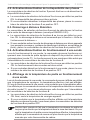
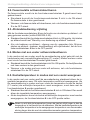
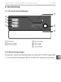
10. Operation
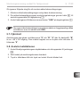
Activating „Standby for remote operation“ with door sensor
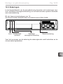
Press the ON/OFF switch, to switch on the sauna control unit.
Press the lower knob (= Temperature selector) for three seconds (=Longpress)
►A countdown of 30 seconds is shown in the lower display. During this time, the door can be opened/
closed as often as you like. After the countdown has expired, the door must be closed!
►The remote start indicator starts ashing.
►The sauna control is now ready to be started and stopped once via a remote start signal = Mode
„Standby for remote operation“
Door is opened - warning „door“ appears in the display
- at mode „Standby for remote operation“:
To continue the mode, the door must be closed and the warning must be acknowledged with a long press
on the lower rotary control. ► The countdown (30 sec.) is shown again in the lower display.
- in operation or enable remot start output (for coinoperated unit or door sensor system):
The acknowledgment takes place automatically when the door is closed.

Version 01/23 Ident-Nr. ST-M-00006-01
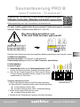
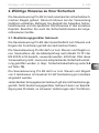
Saunasteuerung PRO B
neue Funktion „Türsensor“
Ergänzung / Änderung zu den Bedienungsanleitungen:
PRO-B2 /1-015-455 , PRO-B3 /1-015-457 Version 12/21
Bedienungsanleitung unter: https://www.sentiotec.com/downloads oder
Die neue Funktion gewährleistet die eine optimale Türüberwachung bei Fernwirken!
optionales Zubehör: Türsensor Home SAB00103 / 1-052-723
Die Anschlussposition von
STB und OSG wurden getauscht!
Beachten Sie die Änderungen in den oben angeführten Bedienungsanleitungen unter folgenden Punkten:
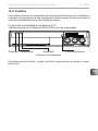
5. Elektrischer Anschluss
Ofenfühler anschließen (rote Leitungen an STB anklemmen)
Sicherheitsabschaltung anschließen bzw. NEU Türsensor anschließen
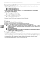
8. Inbetriebnahme
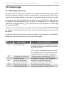
Fernstart-Freigabe:
●Standardmäßig bendet sich der Funktionswahlschalter 4 in OFF-
Position. Der Fernstart wird mittels „Standby für Fernwirken“ aktiviert.
●Wenn Sie den Fernstart-Ausgang für div. Geräte (wie z.B. Münzer,
Türsensor-System) freischalten möchten, bringen Sie den Funkti-
onswahlschalter 4 in ON-Position.
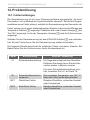
Türsensor aktivieren bei Pro B2
1. Rufen Sie das Techniker-Menü auf (Beim Einschalten gleichzeitig
die Tasten EIN/AUS, Vorwahlzeit und den unteren Drehknopf drücken)
►Im oberen Display erscheint „SdO“
►Im unteren Display erscheint „SAFE“ (=Standardeinstellung)
2. Drehen Sie den unteren Drehknopf nach rechts
►Im unteren Display erscheint “door“
3. Verlassen Sie das Technikermenü (Longpress auf unteren Drehregler)
NEU
STB
Heizzeitbe-
grenzung
Phasen-
rollierung
Fernstart-
Freigabe
Verdampfer-
Single-Betrieb
Fühlerbe-
triebsart
Nicht belegt
Solltemperatur /
Ofentemperatur als
Ist-Temperatur
OFF
OSG
STBOSG
Funktionswahlschalter-
Standardeinstellung
DE

DE
Zusatzblatt zur Bedienungsanleitung S. 2/2
Türsensor aktivieren bei Pro B3
1. Rufen Sie das Techniker-Menü auf (Drücken Sie gleichzeitig die Vorwahlzeit-Taste und den unteren
Drehknopf = Temperaturwähler)
► Im oberen Display erscheint „dry“
► Im unteren Display erscheint „t60
2. Drehen Sie den unteren Drehknopf (Auswahl 0 - 60; 0 = Nachtrockenprogramm ausgesschaltet
60 = maximale Laufzeit in Minuten)
3. Drücken Sie den unteren Drehknopf
►Im oberen Display erscheint „SdO“
►Im unteren Display erscheint „SAFE“
4. Drehen Sie den unteren Drehknopf nach rechts
►Im unteren Display erscheint “door“
5. Verlassen Sie das Technikermenü (Longpress auf unteren Drehregler)
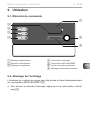
10. Bedienung
Standby für Fernwirken (mit Türsensor) aktivieren
Drücken Sie den EIN/AUS-Schalter, um die Saunasteuerung einzuschalten.
Drücken Sie für 3 Sekunden (=Longpress) den unteren Drehknopf (=Temperaturwähler)
►Im unteren Display wird ein Countdown von 30 Sekunde angezeigt. Die Tür kann in dieser
Zeit beliebig oft geöffnet / geschlossen werden. Nach Ablauf des Countdown muss die Türe
geschlossen sein!
►Die Fernstart-Anzeige blinkt
►Die Saunasteuerung ist nun bereit um über ein Fernstartsignal einmalig gestartet und gestoppt
zu werden = Modus „Standby für Fernwirken“
Tür wird geöffnet - im Display erscheint Warnung „door“
- im Modus Standby für Fernwirken:
Um den Modus fortzusetzen muss die Tür geschlossen werden, und die Warnung muss mittels Longpress
auf den unteren Drehregler quittiert werden. ► Im Display wird wieder der Countdown (30Sek.) angezeigt.
- im laufenden Betrieb oder freigegebenen Fernstart-Ausgang (für Münzer oder Türsensor-System):
Die Quittierung erfolgt automatisch, wenn die Tür geschlossen wird.

Version 12/21 ID no. 1-026-966
EN
FR
IT
NL
SV
FI
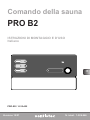
INSTRUCTIONS FOR INSTALLATION AND USE
English
DE
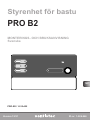
Sauna control unit
PRO B2
PRO-B2 / 1-015-455

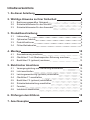
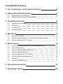
Table of Contents
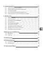
1. About this instruction manual 4
2. Important information for your safety 5
2.1. Intended use 5
2.2. Safety information for the installer 6
2.3. Safety information for the user 7
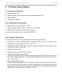
3. Product description 8
3.1. Scope of delivery 8
3.2. Optional accessories 8
3.3. Product functions 8
3.4. Sensor operating modes 9
4. Installation 10
4.1. Installing the sauna control unit 10
4.2. Installing the heater sensor F1 with excess temperature fuse 12
4.3. Installing bench sensor F2 (optional) 13
5. Electrical connection 14
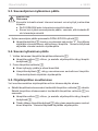
5.1. Connecting the power supply cable and heater cable 15
5.2. Connecting the light 15
5.3. Connecting the power booster (optional) 16
5.4. Connecting heater sensor F1 16
5.5. Installing bench sensor F2 (optional) 16
5.6. Connectingthesafetyshut-o 16
5.7. Remote start 17
5.8. Finishing installation 17
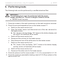
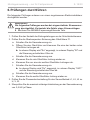
6. Performing tests 18
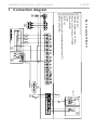
7. Connection diagram 20

EN
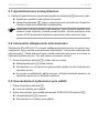
8. Starting-up 21
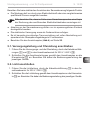
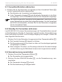
8.1. Setting the heating period limit 21
8.2. Activating/deactivating phase alignment 22
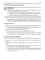
8.3. Remote start release 22
8.4. Activating/deactivating the single-sensor mode 22
8.5. Displaying the heater temperature in single-sensor mode 22
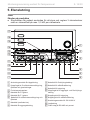
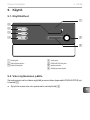
9. Operation 23
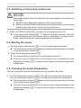
9.1. Operating elements 23
9.2. Switching on the light 23
9.3. Switching on the sauna control unit 24
9.4. Starting the sauna 24
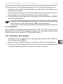
9.5. Changing the preset temperature 24
9.6. Setting the preset time 25
9.7. Cancelling the preset time function 26
9.8. Activating standby for remote operation 26
9.9. Switchingothesaunacontrolunit 26
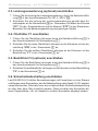
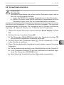
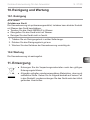
10. Cleaning and maintenance 27
10.1. Cleaning 27
10.2. Maintenance 27
11. Disposal 27
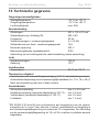
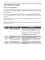
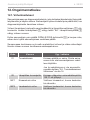
12. Troubleshooting 28
12.1. Error messages 28
12.2. Fuses 29
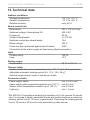
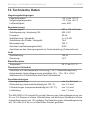
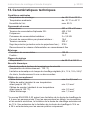
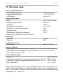
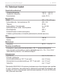
13. Technical data 30

Instructions for installation and use p. 4/30
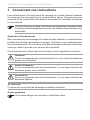
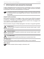
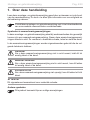
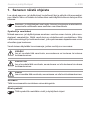
1. About this instruction manual
Read these instructions for installation and use carefully and keep them within
reach of the sauna control unit. This ensures that you can refer to information
regarding your safety and regarding operation at any time.
Symbols used for warning notices
In these instructions for installation and use, a warning notice located next to
an activity indicates that this activity poses a risk. Always observe the warning
notices. This prevents damage to property and injuries, which in the worst case
may be fatal.
The warning notices contain keywords, which have the following meanings:
DANGER!
Serious or fatal injury will occur if this warning notice is not observed.
WARNING!
Serious or fatal injury can occur if this warning notice is not observed.
CAUTION!
Minor injuries can occur if this warning notice is not observed.
ATTENTION!
This keyword is a warning that damage to property can occur.
Other symbols
This symbol indicates tips and useful information.
These installation and operating instructions can also be found in the
downloads section of our website: www.sentiotec.com/downloads.

EN
Instructions for installation and use p. 5/30
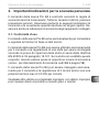
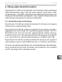
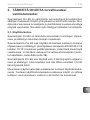
2. Important information for your safety
The sauna control unit Pro B2 has been produced in accordance
with the applicable safety regulations for technical units. However,
hazards may occur during use. Therefore adhere to the following
safetyinformationandthespecicwarningnoticesintheindividual
chapters. Also observe the safety information for the devices con-
nected.
2.1. Intended use
The sauna control unit Pro B2 is used exclusively for operating and
controlling the sauna functions in accordance with the technical data.
The sauna control unit Pro B2 may only be used for operating and
controllingasaunaheaterwhichhasbeencertiedassatisfying
the combustion test described in paragraph 19.101 of EN 60335-
2-53. If the heater does not meet this requirement, an appropriate
safetyprecautionmustbetaken(forexample:safetyshut-o,see
5.6 on page 16).
The sauna control unit Pro B2 may only be used for operating and
controlling 3 heating circuits with a maximum heating capacity
of 3.5 kW per heating circuit.
Any use exceeding this scope is considered improper use. Improper
use can result in damage to the product, in severe injuries or death.

Instructions for installation and use p. 6/30
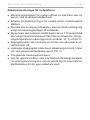
2.2. Safety information for the installer
●Installationmayonlybeperformedbyaqualiedelectricianor
similarlyqualiedperson.
●Work on the sauna control unit may only be performed when the
power has been disconnected.
● Anall-poledisconnectingdevicewithfullcut-ocompliantwith
overvoltagecategoryIIImustbettedon-site.
●The sauna control unit must be installed outside the sauna room
at a height of approx. 1.70 m or in accordance with the rec-
ommendation issued by the sauna manufacturer. The ambient
temperature must be within a range spanning -10 °C to +40 °C.
●The heater sensor must be attached in a way that it is not af-
fectedbyaowofair.
●The heater supply cable must have a minimum cross-section of
2.5 mm2 and be temperature resistant up to 150 °C.
●Also comply with the regulations applicable at the installation
location.
●For your own safety, consult your supplier in the event of prob-
lemsthatarenotexplainedinsucientdetailintheinstallation
instructions.

EN
Instructions for installation and use p. 7/30
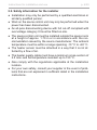
2.3. Safety information for the user
●The sauna control unit must not be used by children under
8 years old.
●The sauna control unit may only be used by children above 8 years
old, by persons with limited psychological, sensory or mental
capabilities or by persons with lack of experience/knowledge:
– When they are supervised.
– When they have been shown how to use the device safely
and are aware of the hazards that could occur.
●Children must not play with the sauna control unit.
●Children under 14 years of age may only clean the sauna control
unit if they are supervised.
● Forhealthreasons,donotusethesaunawhenundertheinu-
ence of alcohol, medication or drugs.
● Makesurethatnoammableobjectshavebeenplacedonthe
sauna heater before the sauna control unit is switched on.
● Makesurethatnoammableobjectshavebeenplacedonthe
heater before activating the preset time function or the stand-by
mode for the remote start.
●For your own safety, consult your supplier in the event of prob-
lemsthatarenotdescribedinsucientdetailintheoperating
instructions.

Instructions for installation and use p. 8/30
3. Product description
3.1. Scope of delivery
●Sauna control unit
●Heater sensor with integrated excess temperature fuse
●Sensor wires
●Installation material
3.2. Optional accessories
●Bench sensor (item number: O-F2)
●Power booster (item number: O-S2-18 / O-S2-30)
● Safetyshut-o(itemnumber:SFE-xxxxx)
●pronet web server (item number: PRO-NET)
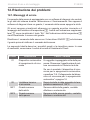
3.3. Product functions
The sauna control unit Pro B2 features the following functions:
●Regulation of sauna heaters with a heating output of up to 10.5 kW in the
temperature range spanning 30 °C to 110 °C.
●A power booster allows the maximum contact rating to be increased from
10.5 kW to 18 kW or 30 kW.
●Remote start function
●Preset time function (up to 24 hours)
●Automatic heating period limiter
The sauna control unit shuts down automatically after the maximum heating
period for safety reasons. The maximum heating period can be set to 6 h,
12 h, 18 h or 24 h.
●Excess temperature fuse
The excess temperature fuse is installed in the housing for the heater sen-
sor. Should the sauna heater continue heating after reaching the preferred
temperature due to a defect, the excess temperature fuse switches the sauna
heateroatatemperatureofapprox.139°C.

EN
Instructions for installation and use p. 9/30
3.4. Sensor operating modes
The sauna control unit can be operated with one or two temperature sensors.
Single-sensor mode (F1)
Single-sensormodemustbeactivatedwhenstartingupthesaunafortherst
time (see 8.3. Activating/deactivating the single-sensor mode on page 22).
In single-sensor mode, the sauna control unit is operated with the heater sensor
with an excess temperature fuse (F1) only. In single-sensor mode, the sauna
control unit only displays the set temperature. The actual temperature is not dis-
played. Should the sauna control unit display the temperature above the heater
(F1) as an actual temperature in single-sensor mode, it must be activated when
startingupforthersttime(see8.4. Displaying the heater temperature in
single-sensor mode on page 22)
Two-sensor mode with bench sensor (F2)
In two-sensor mode with bench sensor, a second temperature sensor (bench
sensor) is installed above the rear sauna bench. The sauna control unit displays
the temperature measured by the bench sensor as the actual temperature.

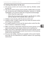
Installation instructions, only for experts p. 10/30
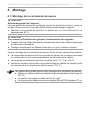
4. Installation
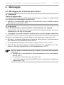
4.1. Installing the sauna control unit
Observe the following points when installing the sauna control unit:
●The sauna control unit must be installed outside the sauna room or in accord-
ance with the recommendation issued by the sauna manufacturer.
●The ambient temperature must be within a range spanning -10 °C to +40 °C.
●The sensors may only be connected using the sensor wires provided with the
unit, which are heat-resistant up to 150 °C.
ATTENTION!
Damage to the unit
The sauna control unit is protected against jets of water, however direct contact
with water could still damage the unit.
●Install the sauna control unit in a dry place at which a maximum humidity of
95 % is not exceeded.
The sensor wires may be extended under the following conditions:
●When a silicon wire resistant to temperatures up to 150 °C is used.
●The minimum cross-section of the wire is 0.5 mm2.
●The length of the heater sensor wires may NOT exceed 10 m.
ATTENTION!
Sources of interference can have a negative eect on signal transmission
●Lay all sensor wires separately from other mains wires and control wires.
●Protect wires with only one layer of insulation by using a pipe (double insulation).

EN
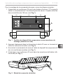
Instructions for installation and use p. 11/30
82
80
34
175
145
34
43
40
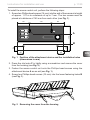
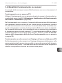
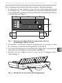
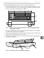
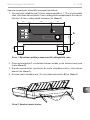
Fig. 1 Position of the attachment device and the installation holes
(dimensions in mm)
C
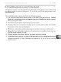
To install the sauna control unit, perform the following steps:
1. Screw two Phillips-head screws (16 mm) into the wall of the sauna at a height
of approx. 1.70 m to a distance of up to 7 mm. The two screws must be
placed at a distance of 145 mm from each other (see Fig. 1).
2. Press the clip locks C in lightly using a screwdriver and remove the cover
from the housing (see Fig. 2).
3. Fasten the sauna control unit onto the Phillips-head screws using the
attachment device A as an aid (see Fig. 1).
4. Screw two Phillips-head screws (16 mm) into the lower fastening holes B
(see Fig. 1).
A
B
Fig. 2 Removing the cover from the housing

Installation instructions, only for experts p. 12/30
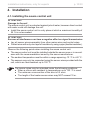
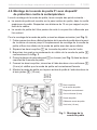
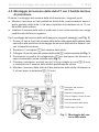
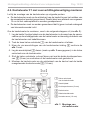
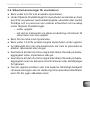
4.2. Installing the heater sensor F1 with excess temperature fuse
Observe the following points when installing the heater sensor:
●The heater sensor must be installed on the rear of the heater, above the mid-
dle of the sauna heater. An interval of approx. 15 cm to the roof of the sauna
room must be maintained.
●The heater sensor must be attached in a way that it is not affected by
aowofair.
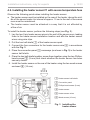
To install the heater sensor, perform the following steps (see Fig. 3):
1. Lay the two 2-pin heater sensor wires in the wall of the sauna room, leading
themtotheheatersensorinstallationlocationandaxtheheatersensor
wires using wire clips.
2. Pull the two half-shells 1 of the heater sensor apart.
3. Connect the four connectors for the heater sensor wire 5 in accordance
with the Fig. 3.
4. Place the connection panel 2 crossways (as shown in Fig. 3) in the heater
sensor half-shells.
5. Place the two half-shells together, screw them together using the two Phillips-
head screws 3 (9 mm) and check whether the heater sensor has been
securely closed.
6. Install the heater sensor on the rear of the heater using the two wood screws
enclosed 6 (16 mm).
1 Heater sensor half-shells
2 Connection panel
3 Phillips-head screws (9 mm)
4 Heater sensor
5 Heater sensor wires
6 Wood screws (16 mm)
Fig. 3 Installing the
heater sensor
red
white
white
red

EN
Instructions for use for the user p. 13/30
4.3. Installing bench sensor F2 (optional)
The bench sensor must be installed on the wall of the sauna room, above the
rear bench seat. An interval of approx. 15 cm to the roof of the sauna room must
be maintained.
To install the bench sensor, perform the following steps:
1. Lay the two 2-pin bench sensor wires in the wall of the sauna room, leading
themtothebenchsensorinstallationlocationandaxthebenchsensor
wires using wire clips.
2. Pull the two half-shells of the bench sensor apart.
3. Connect the two connectors for the bench sensor wire to the two middle
terminals on the connection panel.
4. Place the connection panel crossways in the bench sensor half-shells.
5. Place the two half-shells together and screw them together using the two
Phillips-head screws (9 mm).
6. Check whether the bench sensor has been securely closed.
7. Install the bench sensor on the wall of the sauna room using the two wood
screws enclosed (16 mm). Maintain an interval of 15 cm to the roof of the
sauna room.

Installation instructions, only for experts p. 14/30
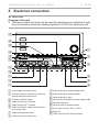
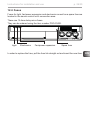
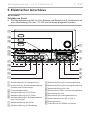
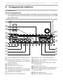
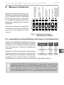
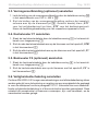
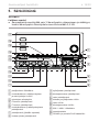
5. Electrical connection
ATTENTION!
Damage to the unit
●The sauna control unit may only be used for operating and controlling 3 heat-
ing circuits with a maximum heating capacity of 3.5 kW per heating circuit.
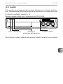
1
2
4
3
5
6
b
7
8
9
a
c
d
e
f
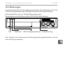
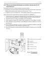
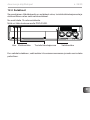
1 Low-voltage connection area
2 Terminalstripsforsafetyshut-odevice,
remote start and sensor wires
3 Function selection switch
4 Cable bushing for F2 sensor
5 Cable bushing for F1 sensor
6 Cablebushingforsafetyshut-odevice
and remote start
7 Cable bushing (leave free)
8 Cable bushing for heater wire
9 Cable bushing for power supply cable
a Cable bushing for power booster
b Cable bushing for light
c
Terminal strip for heater and power supply cable
d Terminal strip light
e Terminal strip for power booster
f Connection area for 230 V / 400 V
g Earth rail
h RJ45 socket for RS-485 and pronet
g
h

EN
Installation instructions, only for experts p. 15/30
Observe the following points when connecting the power to the sauna control unit:
●Installationmayonlybeperformedbyaqualiedelectricianorsimilarlyquali-
edperson.
Please observe that in the event of a guarantee claim, a copy of the bill
from the electrician performing the work must be presented.
●Work on the sauna control unit may only be performed when the power has
been disconnected.
● Theremustbeaxedconnectionfortheelectricalpowersupply.
● Anall-poledisconnectingdevicewithfullcut-ocompliantwithovervoltage
categoryIIImustbettedon-site.
●Observe the connection diagram (Fig. 4) on page 20.
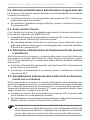
5.1. Connecting the power supply cable and heater cable
1. Guide the power supply and heater cable through the cable bushings 9
and 8 into the connection area for 230 V/400 V f.
2. Connect the power supply cables to the terminal strip c in accordance
with the connection diagram. Observe the operating instructions for the
respective devices.
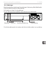
5.2. Connecting the light
1. Guide the light cable through the cable bushing b into the connection area
for 230 V/400 V f.
2. Connect the light cable to the terminal strip d in accordance with the con-
nection diagram. Observe the operating instructions for the respective device.

Installation instructions, only for experts p. 16/30
5.3. Connecting the power booster (optional)
1. Guide the cable for the power booster through the cable bushing a into
the connection area for 230 V/400 V g.
2. Connect the cable for the power booster to the terminal strip e
in accordance with the connection diagram. To do so, use terminal
“ST1” for the safety circuit, and terminal “ST2” for the control circuit.
Observe the operating instructions for the respective device.
5.4. Connecting heater sensor F1
1. Guide the wires for the heater sensor through the cable bushing 5 into the
low-voltage connection area 1.
2. Connect the red wires for the heater sensor to the terminals labelled “STB”
in terminal strip 2.
3. Connect the white wires for the heater sensor to the terminals labelled “F1”
in terminal strip 2.
5.5. Installing bench sensor F2 (optional)
1. Guide the wires for the bench sensor through the cable bushing 4 into the
low-voltage connection area 1.
2. Connect the wires for the bench sensor to the terminals labelled “F2” in
terminal strip 2.
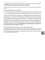
5.6. Connecting the safety shut-o
EN 60335-2-53 states that sauna control units with remote control may only be
usedforoperatingandregulatingasaunaheaterwhichhassatisedthecombus-
tiontestdescribedinparagraph19.101.Alternatively,asuitablesafetyshut-o
devicecanbeinstalledinorabovetheheater.Thisshutsthesaunaheatero
when objects, e.g. a towel, are placed on the sauna heater.
La page est en cours de chargement...
La page est en cours de chargement...
La page est en cours de chargement...
La page est en cours de chargement...
La page est en cours de chargement...
La page est en cours de chargement...
La page est en cours de chargement...
La page est en cours de chargement...
La page est en cours de chargement...
La page est en cours de chargement...
La page est en cours de chargement...
La page est en cours de chargement...
La page est en cours de chargement...
La page est en cours de chargement...
La page est en cours de chargement...
La page est en cours de chargement...
La page est en cours de chargement...
La page est en cours de chargement...
La page est en cours de chargement...
La page est en cours de chargement...
La page est en cours de chargement...
La page est en cours de chargement...
La page est en cours de chargement...
La page est en cours de chargement...
La page est en cours de chargement...
La page est en cours de chargement...
La page est en cours de chargement...
La page est en cours de chargement...
La page est en cours de chargement...
La page est en cours de chargement...
La page est en cours de chargement...
La page est en cours de chargement...
La page est en cours de chargement...
La page est en cours de chargement...
La page est en cours de chargement...
La page est en cours de chargement...
La page est en cours de chargement...
La page est en cours de chargement...
La page est en cours de chargement...
La page est en cours de chargement...
La page est en cours de chargement...
La page est en cours de chargement...
La page est en cours de chargement...
La page est en cours de chargement...
La page est en cours de chargement...
La page est en cours de chargement...
La page est en cours de chargement...
La page est en cours de chargement...
La page est en cours de chargement...
La page est en cours de chargement...
La page est en cours de chargement...
La page est en cours de chargement...
La page est en cours de chargement...
La page est en cours de chargement...
La page est en cours de chargement...
La page est en cours de chargement...
La page est en cours de chargement...
La page est en cours de chargement...
La page est en cours de chargement...
La page est en cours de chargement...
La page est en cours de chargement...
La page est en cours de chargement...
La page est en cours de chargement...
La page est en cours de chargement...
La page est en cours de chargement...
La page est en cours de chargement...
La page est en cours de chargement...
La page est en cours de chargement...
La page est en cours de chargement...
La page est en cours de chargement...
La page est en cours de chargement...
La page est en cours de chargement...
La page est en cours de chargement...
La page est en cours de chargement...
La page est en cours de chargement...
La page est en cours de chargement...
La page est en cours de chargement...
La page est en cours de chargement...
La page est en cours de chargement...
La page est en cours de chargement...
La page est en cours de chargement...
La page est en cours de chargement...
La page est en cours de chargement...
La page est en cours de chargement...
La page est en cours de chargement...
La page est en cours de chargement...
La page est en cours de chargement...
La page est en cours de chargement...
La page est en cours de chargement...
La page est en cours de chargement...
La page est en cours de chargement...
La page est en cours de chargement...
La page est en cours de chargement...
La page est en cours de chargement...
La page est en cours de chargement...
La page est en cours de chargement...
La page est en cours de chargement...
La page est en cours de chargement...
La page est en cours de chargement...
La page est en cours de chargement...
La page est en cours de chargement...
La page est en cours de chargement...
La page est en cours de chargement...
La page est en cours de chargement...
La page est en cours de chargement...
La page est en cours de chargement...
La page est en cours de chargement...
La page est en cours de chargement...
La page est en cours de chargement...
La page est en cours de chargement...
La page est en cours de chargement...
La page est en cours de chargement...
La page est en cours de chargement...
La page est en cours de chargement...
La page est en cours de chargement...
La page est en cours de chargement...
La page est en cours de chargement...
La page est en cours de chargement...
La page est en cours de chargement...
La page est en cours de chargement...
La page est en cours de chargement...
La page est en cours de chargement...
La page est en cours de chargement...
La page est en cours de chargement...
La page est en cours de chargement...
La page est en cours de chargement...
La page est en cours de chargement...
La page est en cours de chargement...
La page est en cours de chargement...
La page est en cours de chargement...
La page est en cours de chargement...
La page est en cours de chargement...
La page est en cours de chargement...
La page est en cours de chargement...
La page est en cours de chargement...
La page est en cours de chargement...
La page est en cours de chargement...
La page est en cours de chargement...
La page est en cours de chargement...
La page est en cours de chargement...
La page est en cours de chargement...
La page est en cours de chargement...
La page est en cours de chargement...
La page est en cours de chargement...
La page est en cours de chargement...
La page est en cours de chargement...
La page est en cours de chargement...
La page est en cours de chargement...
La page est en cours de chargement...
La page est en cours de chargement...
La page est en cours de chargement...
La page est en cours de chargement...
La page est en cours de chargement...
La page est en cours de chargement...
La page est en cours de chargement...
La page est en cours de chargement...
La page est en cours de chargement...
La page est en cours de chargement...
La page est en cours de chargement...
La page est en cours de chargement...
La page est en cours de chargement...
La page est en cours de chargement...
La page est en cours de chargement...
La page est en cours de chargement...
La page est en cours de chargement...
La page est en cours de chargement...
La page est en cours de chargement...
La page est en cours de chargement...
La page est en cours de chargement...
La page est en cours de chargement...
La page est en cours de chargement...
La page est en cours de chargement...
La page est en cours de chargement...
La page est en cours de chargement...
La page est en cours de chargement...
La page est en cours de chargement...
La page est en cours de chargement...
La page est en cours de chargement...
La page est en cours de chargement...
La page est en cours de chargement...
La page est en cours de chargement...
La page est en cours de chargement...
La page est en cours de chargement...
La page est en cours de chargement...
La page est en cours de chargement...
La page est en cours de chargement...
La page est en cours de chargement...
La page est en cours de chargement...
La page est en cours de chargement...
La page est en cours de chargement...
La page est en cours de chargement...
La page est en cours de chargement...
La page est en cours de chargement...
La page est en cours de chargement...
La page est en cours de chargement...
La page est en cours de chargement...
-
 1
1
-
 2
2
-
 3
3
-
 4
4
-
 5
5
-
 6
6
-
 7
7
-
 8
8
-
 9
9
-
 10
10
-
 11
11
-
 12
12
-
 13
13
-
 14
14
-
 15
15
-
 16
16
-
 17
17
-
 18
18
-
 19
19
-
 20
20
-
 21
21
-
 22
22
-
 23
23
-
 24
24
-
 25
25
-
 26
26
-
 27
27
-
 28
28
-
 29
29
-
 30
30
-
 31
31
-
 32
32
-
 33
33
-
 34
34
-
 35
35
-
 36
36
-
 37
37
-
 38
38
-
 39
39
-
 40
40
-
 41
41
-
 42
42
-
 43
43
-
 44
44
-
 45
45
-
 46
46
-
 47
47
-
 48
48
-
 49
49
-
 50
50
-
 51
51
-
 52
52
-
 53
53
-
 54
54
-
 55
55
-
 56
56
-
 57
57
-
 58
58
-
 59
59
-
 60
60
-
 61
61
-
 62
62
-
 63
63
-
 64
64
-
 65
65
-
 66
66
-
 67
67
-
 68
68
-
 69
69
-
 70
70
-
 71
71
-
 72
72
-
 73
73
-
 74
74
-
 75
75
-
 76
76
-
 77
77
-
 78
78
-
 79
79
-
 80
80
-
 81
81
-
 82
82
-
 83
83
-
 84
84
-
 85
85
-
 86
86
-
 87
87
-
 88
88
-
 89
89
-
 90
90
-
 91
91
-
 92
92
-
 93
93
-
 94
94
-
 95
95
-
 96
96
-
 97
97
-
 98
98
-
 99
99
-
 100
100
-
 101
101
-
 102
102
-
 103
103
-
 104
104
-
 105
105
-
 106
106
-
 107
107
-
 108
108
-
 109
109
-
 110
110
-
 111
111
-
 112
112
-
 113
113
-
 114
114
-
 115
115
-
 116
116
-
 117
117
-
 118
118
-
 119
119
-
 120
120
-
 121
121
-
 122
122
-
 123
123
-
 124
124
-
 125
125
-
 126
126
-
 127
127
-
 128
128
-
 129
129
-
 130
130
-
 131
131
-
 132
132
-
 133
133
-
 134
134
-
 135
135
-
 136
136
-
 137
137
-
 138
138
-
 139
139
-
 140
140
-
 141
141
-
 142
142
-
 143
143
-
 144
144
-
 145
145
-
 146
146
-
 147
147
-
 148
148
-
 149
149
-
 150
150
-
 151
151
-
 152
152
-
 153
153
-
 154
154
-
 155
155
-
 156
156
-
 157
157
-
 158
158
-
 159
159
-
 160
160
-
 161
161
-
 162
162
-
 163
163
-
 164
164
-
 165
165
-
 166
166
-
 167
167
-
 168
168
-
 169
169
-
 170
170
-
 171
171
-
 172
172
-
 173
173
-
 174
174
-
 175
175
-
 176
176
-
 177
177
-
 178
178
-
 179
179
-
 180
180
-
 181
181
-
 182
182
-
 183
183
-
 184
184
-
 185
185
-
 186
186
-
 187
187
-
 188
188
-
 189
189
-
 190
190
-
 191
191
-
 192
192
-
 193
193
-
 194
194
-
 195
195
-
 196
196
-
 197
197
-
 198
198
-
 199
199
-
 200
200
-
 201
201
-
 202
202
-
 203
203
-
 204
204
-
 205
205
-
 206
206
-
 207
207
-
 208
208
-
 209
209
-
 210
210
-
 211
211
-
 212
212
-
 213
213
-
 214
214
-
 215
215
-
 216
216


Sentiotec PRO-B2 Sauna Control PRO B Manuel utilisateur
- Taper
- Manuel utilisateur
dans d''autres langues
- italiano: Sentiotec PRO-B2 Sauna Control PRO B Manuale utente
- English: Sentiotec PRO-B2 Sauna Control PRO B User manual
- Deutsch: Sentiotec PRO-B2 Sauna Control PRO B Benutzerhandbuch
- Nederlands: Sentiotec PRO-B2 Sauna Control PRO B Handleiding
- eesti: Sentiotec PRO-B2 Sauna Control PRO B Kasutusjuhend
Documents connexes
-
Sentiotec Pro B3 Manuel utilisateur
-
-
-
-
-
-
-
-
-