
1 | minnkotamotors.com
©2020 Johnson Outdoors Marine Electronics, Inc.
Before mounting your Raptor Direct Mount Adapter Bracket, please
give consideration to the following:
1. Unobstructed Mounting - When selecting the mounting location,
examine your boat to ensure that you will not drill into any
obstructions and that the hardware will be accessible for assembly.
Make sure that the Transom is strong enough to accept the Raptor
mounted at the intended location.
2. Unobstructed Deployment and Retraction - The Raptor is
designed to mount on either the port or starboard side of the
transom. The Raptor must have a clear, unobstructed path to
deploy. Check to make sure that your proposed location will allow
the anchor to deploy and retract without hitting trim tabs, poling
platforms, ladders, the engine or other obstructions. You should
also consider your fishing methods when selecting the
mounting location.
Item /
Assembly
Part # Description Qty.
2
2351924 BRACKET,DIRECT MNT PAINTED 1
2351928 BRKT, DIRECT MNT, PAINT WHT *white* 1
s
2354913 INSTRC-INSTALL, DIRECT MNT 1
A
Items 4 - 10
2994940 BAG ASM,SETBACK HDW,RPTR 1
4 2371758 WASHER-3/8 HD FLAT SS 4
6 2353102 NUT-3/8-16 FLANGE,NYLOK,SS 4
8 2383422 SCREW-3/8-16 X 1 1/4 HHCS SS 4
10 2378608 ANTI SEIZE TUBE, 4CC 1
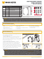
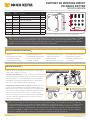
MOUNTING CONSIDERATIONS
RAPTOR DIRECT MOUNT
ANGLE BRACKET
1810371 & 1810376
✖ This part is included in an assembly and cannot be ordered individually. s Not shown on Parts Diagram.
NOTICE: When mounting the Direct Mount Angle Bracket to the Transom it is recommended to review the additional mounting
considerations for the complete installation of the Raptor. They can be found online at minnkotamotors.com in the “Installation” section
of the Raptor Owner’s Manual or Installation Instructions. They including how to mount the Hydraulic Pump and route the Hydraulic
Hoses along with other recommendations. To add the 3” Setback Bracket (1810370 or 1810375 - white), finish the installation of the
Direct Mount Bracket (Item #2) and then find additional instructions in the 3” Setback Bracket Installation Instructions.
2
8
4
6
10
A
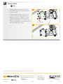
The Raptor Direct Mount Angle Bracket can be installed directly to either the port or starboard transom of the boat.
NOTICE: For use with Raptor Shallow Water Anchors. Use the Direct Mount Angle Bracket (1810371 and 1810376 - white) when additional
setback is needed and the Raptor needs to be offset to provide mounting clearance. May be mounted directly to either the Port or Starboard
of the transom. The 3” Setback Bracket (1810370 and 1810375 - white) may also be paired with the Raptor Direct Mount Angle Bracket.
• Drill
• 9⁄16" Box End or Socket Wrench
• Marine Grade Sealant
• 20ft/lb capacity Torque Wrench
• Awl or similar marking tool
• Masking Tape
• A second person to help with installation
• 7/16" Drill Bit
• File, sand paper, or emery board
• Installation Hardware Kit 2994943
included with Raptor
TOOLS AND RESOURCES REQUIRED
Complete Typical Installation
2
Port
2
Starboard

2 | minnkotamotors.com
©2020 Johnson Outdoors Marine Electronics, Inc.
Correct
Incorrect
RaptorRaptor
RaptorRaptor
Raptor Raptor
Range of MotionRange of Motion
3
3
4
2" 2"
MinimumMinimum
4" Minimum4" Minimum
Hull directly
below Raptor
Hull directly below Raptor
Outboard Motor Outboard Motor
Range of MotionRange of Motion
Bottom Edge Bottom Edge
of Raptorof Raptor
Bottom Bottom
Edge of Edge of
RaptorRaptor
4" Minimum4" Minimum
2" 2"
MinimumMinimum
2" 2"
MinimumMinimum
2" 2"
MinimumMinimum
Slotted Slotted
Mounting Mounting
HolesHoles
Slotted Slotted
Mounting Mounting
HolesHoles
OutboardOutboard
InboardInboard
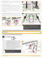
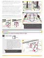
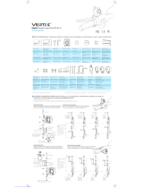
3. Raptor to Hull Clearance - The bottom edge of the Raptor should
never be less than 4” above the hull directly below the Raptor to
prevent spray and drag conditions.
4. Raptor to Engine Clearance - When selecting a mounting location,
make sure that no interference exists between the Raptor and
your engine during normal operation. Once you have selected your
mounting location, trim the engine all the way up and all the way
down, and steer the engine fully to the left and right to confirm
proper engine clearance. Ensure there is a minimum of two to three
inches of clearance from any point on the Raptor in all states of
stow and deploy.
5. Outboard Slotted Mounting Holes - When mounted on either the
Port or Starboard side, the bracket should always be oriented to
face away from the engine, with the slotted holes facing away from
the transom.
NOTICE: To prevent seizing of the stainless steel
hardware, do not use high speed installation tools.
Wetting the screws or applying an anti-seize may help
prevent seizing.
RaptorRaptor
RaptorRaptor
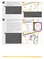
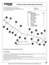
Installing the Direct Mount Angle Bracket
a. Review the Mounting Considerations to determine
if it is acceptable to complete a direct mount of the
Raptor Direct Mount Angle Bracket. If acceptable,
position the Direct Mount Angle Bracket (Item
#2) at the selected location. Make sure that the
Slotted Mounting Holes are positioned away from
the Transom and facing Outboard. With the bracket
level and in place, mark all four Mounting Holes
with an awl or similar marking tool.
1
1a
ITEM(S) NEEDED
#2 x 1
TransomTransom
Direct Mount Direct Mount
Angle BracketAngle Bracket
INSTALLATION
Mounting HolesMounting Holes
Slotted Slotted
Mounting HolesMounting Holes
Mounting HolesMounting Holes
Marked Marked
LocationsLocations
OutboardOutboard
NOTICE: It is recommended to have a second
person help with installation.

3 | minnkotamotors.com
©2020 Johnson Outdoors Marine Electronics, Inc.
2
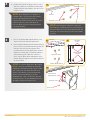
NOTICE: When drilling the marked holes, make sure
that the drill bit is perpendicular to the Transom/Stern of
the boat and that the holes are being drilled straight. Not
drilling the holes straight will give the mounting hardware
a poor fit.
NOTICE: To install the Raptor Direct Mount Angle
Bracket to the boat, the Hardware Kit (Assembly
2994943) included with the Raptor will be needed.
This includes Four (Part #2371758) Flat Head
Stainless Steel Washers, Four (Part #2371759)
Stainless Steel Fender Washers, Four (Part
#2383421) 3/8 - 16 X 3 1/2 Stainless Steel Hex
Head Cap Screws, Four (Part #2353102) Stainless
Steel Nylock Flange Nuts and anti-seize.
NOTICE: When drilling holes into fiberglass, it
is helpful to first cover the surface with masking
tape. This will help keep the boat surface
unmarked and help with cleanup. Cover the surface
and then mark the location to drill. Once the
holes are drilled, remove the masking tape before
continuing installation.
b. Double check that the mounting location is clear to
drill holes and then use a Drill with a 7/16" Drill Bit
to drill through the Transom/Stern of the boat on the
marked locations.
2b
TransomTransom
Drilled LocationDrilled Location
Marked LocationMarked Location
3c
Drilled LocationDrilled Location
c. Place a 1/8" bead of Marine Grade Sealant on the
Transom of the boat around the drilled holes.
d. Place the Marine Grade Sealant around the Mounting
Holes on the face of the Direct Mount Angle Bracket
that will contact the boat Transom/Stern when
mounted. Keep the sealant approximately centered
between the outside edge of the Mounting Bracket
and the Mounting Holes. Once the sealant is in
place, align the Direct Mount Angle Bracket in the
desired orientation with the holes that were drilled in
the Transom/Stern.
3
3d
Marine Grade SealantMarine Grade Sealant
Transom
Marine Grade
Sealant
Mounting Mounting
HolesHoles
Mounting HolesMounting Holes
3d
TransomTransom
Drilled LocationDrilled Location
Direct Mount Direct Mount
Angle BracketAngle Bracket

4 | minnkotamotors.com
©2020 Johnson Outdoors Marine Electronics, Inc.
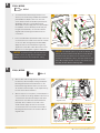
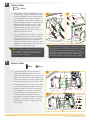
e. To install the Direct Mount Angle bracket to the
Transom, use the Mounting Hardware Kit 2994943
provided with the Raptor. Take each of the four
3-1/2" Stainless Steel Hex Head Cap Screws (Part
#2383421) and place one Flat Washer (Part
#2371758) on them. Apply anti-seize (Item #10) to
the hardware. The Hex Head Cap Screws will pass
thought the Flat Washers, into the Direct Mount
Angle Bracket and through the Drilled locations
on the Boat.
f. Place a Fender Washer (Part #2371759) on the end
of each Screw on the inside of the Transom and then
secure each with a Flange Nut (Part #2353102).
Apply anti-seize to the threads before tightening.
Tighten the screws with a 9/16" Box End or Socket
Wrench. Do not over-tighten. Tighten to 20 ft-lbs.
4
4e 4f
NOTICE: To prevent seizing of the stainless steel
hardware, do not use high speed installation tools.
Applying an anti-seize may help prevent seizing.
TransomTransom
Flange
Nut
Stainless Steel Hex Stainless Steel Hex
Head Cap ScrewsHead Cap Screws
Direct Direct
Mount Mount
Angle Angle
BracketBracket
Direct Direct
Mount Mount
Angle Angle
BracketBracket
Flat Flat
WashersWashers
NOTICE: An alternate option is to mount the bracket, by
passing the Hex Head Cap Screw with the Fender Washer
from the inside of the transom to the outside. Pass the
Screws into the Drilled Locations. Then pass them into the
Direct Mount Angle Bracket. Secure on the outside of the
boat with the Flat Washer and Flange Nut.
ITEM(S) NEEDED
#10 x 1
Fender
Washer
5
5g
5h
TransomTransom
TransomTransom
Mounting
Bracket
Flat Washers
Hex Head
Cap Screws
Direct Mount Direct Mount
Angle BracketAngle Bracket
Direct Mount Direct Mount
Angle BracketAngle Bracket
Slotted HolesSlotted Holes
Slotted HolesSlotted Holes
Raptor
g. With the Direct Mount Angle Bracket secured to
the Transom, take the Raptor and align the Raptor
Mounting Bracket with the Slotted Holes on the
Direct Mount Angle Bracket. Notice that the holes
are slotted so that the Raptor can be adjusted along
the slots for the final installation.
h. With the help of a second person, hold the Raptor in
place to install the mounting hardware. Take the four
1-1/4 Stainless Steel Hex Head Cap Screws (Item
#8) and four of the Stainless Steel Flat Washers
(Item #4). Place a Washer on the end of each
Screw and then apply anti-seize to the threads
of each Screw. Insert each Screw into the Raptor
Mounting Bracket and then into the Direct Mount
Angle Bracket.
ITEM(S) NEEDED
#4 x 4#8 x 4

6
6i
Flanged NutsFlanged Nuts
i. Take four of the Flange Nuts and place one on the
end of each of the Hex Head Cap Screws. Secure
them loosely.
j. Then check the angle of the bracket along the
Slotted Holes and confirm that the Raptor is set at
the desired angle along the holes. Apply anti-seize to
the threads before tightening. Once set, tighten the
Flange Nuts with a 9/16” Box End or Socket Wrench.
Do not over-tighten. Tighten to 20 ft-lbs.
ITEM(S) NEEDED
#6 x 4
Minn Kota Consumer & Technical Service
Johnson Outdoors Marine Electronics, Inc.
PO Box 8129
Mankato, MN 56001
121 Power Drive
Mankato, MN 56001
Phone (800) 227-6433
Fax (800) 527-4464
minnkotamotors.com
©2020 Johnson Outdoors Marine Electronics, Inc.
All rights reserved.
Part #2354913 Rev B 06/20ECN 40715
For warranty information, please visit minnkotamotors.com.
6j

6 | minnkotamotors.com
©2020 Johnson Outdoors Marine Electronics, Inc.
Avant de monter votre support de montage direct en angle Raptor,
veiller à tenir compte de ce qui suit :
1. Montage sans obstruction - Lors de la sélection de l’emplacement
de montage, examiner le bateau afin de s’assurer de ne pas percer
dans une obstruction et que la quincaillerie sera accessible pour
l’assemblage. S’assurer que le tableau arrière est suffisamment
fort pour accepter le Raptor monté à l’endroit prévu.
2. Déploiement et rétraction sans obstruction - Le Raptor est conçu
pour être monté côté bâbord ou côté tribord du tableau arrière. Le
Raptor doit avoir une voie claire, sans obstruction pour le déploiement.
S’assurer que l’emplacement proposé permettra le déploiement et la
rétraction de l’ancre sans heurter les volets, les plateformes de
poussée, les échelles, le moteur ou d’autres obstructions. On devrait
aussi tenir compte des méthodes de pêche lors de la sélection de
l’emplacement de montage.
Article/
Assemblage
Nº de
pièce
Description Qté.
2
2351924 BRACKET,DIRECT MNT PAINTED 1
2351928 BRKT, DIRECT MNT, PAINT WHT *blanc* 1
s
2354913 INSTRC-INSTALL, DIRECT MNT 1
A
articles 4 - 10
2994940 BAG ASM,SETBACK HDW,RPTR 1
4 2371758 WASHER-3/8 HD FLAT SS 4
6 2353102 NUT-3/8-16 FLANGE,NYLOK,SS 4
8 2383422 SCREW-3/8-16 X 1 1/4 HHCS SS 4
10 2378608 ANTI SEIZE TUBE, 4CC 1
FACTEURS DE MONTAGE
SUPPORT DE MONTAGE DIRECT
EN ANGLE RAPTOR
1810371 & 1810376
s Non illustrée sur le schéma des pièces.✖ Cette pièce est incluse dans un ensemble et ne peut pas être commandée individuellement..
AVIS : Lors du montage du support de montage direct en angle au tableau arrière, on recommande de consulter les facteurs de
montage supplémentaires pour une installation complète du Raptor. Ils se trouvent en ligne sur minnkotamotors.com idans la section
« Installation » du manuel du propriétaire ou des instructions d’installation du Raptor. Ils indiquent comment monter la pompe
hydraulique et acheminer les tuyaux hydrauliques, ainsi que d’autres recommandations. Pour ajouter le support de décalage de 3
po (7,6 cm) (1810370 ou 1810375 - blanc), terminer l’installation du support de montage direct (article nº 2), puis consulter les
instructions supplémentaires dans les instructions d’installation du support de décalage de 3 po (7,6 cm).
2
8
4
6
10
A
Le support de montage direct en angle Raptor peut être installé directement sur le tableau arrière du bateau, et ce, à bâbord ou à tribord.
AVIS : À utiliser avec les ancres pour eaux peu profondes Raptor Utiliser le support de montage direct en angle (1810371 et 1810376
- blanc) quand il faut un décalage supplémentaire et que le Raptor doit être décalé pour qu’il y ait le dégagement qu’il faut pour le
montage. Peut être monté directement à bâbord ou à tribord du tableau arrière. Le support de décalage de 3 po (7,6 cm) (1810370 et
1810375 - blanc) peut aussi être jumelé au support de montage direct en angle Raptor.
• Perceuse
• Clé polygonale ou à cliquet
de 9/16 po (14,3 mm)
• Scellant de qualité marine
• Clé dynamométrique d’une
capacité de 20 pi-lb (27,1 Nm)
• Poinçon ou autre outil de
marquage semblable
• Une deuxième personne pour
aider avec l’installation
• Ruban à masquer
• Mèche de 7/16 po (11,1 mm)
• Lime, papier sablé ou lime-émeri
• Ensemble de quincaillerie
d’installation 2994943 inclus
avec le Raptor
OUTILS ET RESSOURCES NÉCESSAIRES
Installation complète typique
2
Bâbord
2
Tribord

7 | minnkotamotors.com
©2020 Johnson Outdoors Marine Electronics, Inc.
Correct
Incorrect
RaptorRaptor
RaptorRaptor
Plage de Plage de
mouvement du Raptormouvement du Raptor
3
3
4
Minimum Minimum
de 2 po de 2 po
(5,1 cm)(5,1 cm)
Minimum de 4 po (10,2 cm)Minimum de 4 po (10,2 cm)
Coque directement
sous le Raptor
Coque directement
sous le Raptor
Amplitude de Amplitude de
mouvement du mouvement du
moteur hors-bordmoteur hors-bord
Bord inférieur Bord inférieur
du Raptordu Raptor
Bord Bord
inférieur inférieur
du Raptordu Raptor
Minimum de 4 po (10,2 cm)Minimum de 4 po (10,2 cm)
Minimum Minimum
de 2 po de 2 po
(5,1 cm)(5,1 cm)
Minimum de Minimum de
2 po (5,1 cm)2 po (5,1 cm)
Minimum de Minimum de
2 po (5,1 cm)2 po (5,1 cm)
Trous de Trous de
montage à montage à
fentefente
Slotted Slotted
Mounting Mounting
HolesHoles
Hors-bordHors-bord
En-bordEn-bord
3. Dégagement entre le Raptor et la coque - Le bord inférieur du
Raptor ne devrait jamais être inférieur à 4 po (10,2 cm) au-dessus
de la coque, directement sous le Raptor afin d’empêcher des
conditions de jet d’eau ou de traînée.
4. Dégagement entre le Raptor et le moteur - Lors de la sélection d’un
emplacement de montage, s’assurer qu’il n’y a aucune interférence
entre le Raptor et le moteur au cours du fonctionnement normal.
Lorsque l’emplacement de montage est sélectionné, ajuster la
compensation du moteur au maximum vers le haut et le bas, et tourner
le moteur complètement vers la droite et la gauche pour confirmer le
dégagement approprié du moteur. S’assurer qu’il y a un minimum de
deux à trois pouces (5,1 à 7,6 cm) de dégagement de tout point du
Raptor, dans toutes les positions d’arrimage et de déploiement.
5. Trous de montage à fente du hors-bord - Quand il est monté côté
bâbord ou côté tribord, le support devrait toujours être orienté dans
le sens opposé du moteur, les trous à fente étant orientés dans le
sens opposé du tableau arrière.
AVIS : Pour prévenir le grippage de la quincaillerie en
acier inoxydable, ne pas utiliser d’outils haute vitesse pour
l’installation. Le fait de mouiller les vis ou d’appliquer un
produit antigrippant peut aider à prévenir qu’elles grippent.
RaptorRaptor
RaptorRaptor
Installation du support de montage direct en angle
a. Relire les facteurs de montage afin de déterminer
s’il est acceptable d’effectuer un montage direct du
support de montage direct en angle Raptor. Si oui,
positionner le support de montage direct en angle
(article nº 2) à l’emplacement sélectionné. S’assurer
que les trous de montage à fente sont orientés dans
le sens opposé du tableau arrière et dans le sens du
hors-bord. Le support à niveau et en place, marquer
les trous de montage avec un poinçon ou outil de
marquage semblable.
1
1a
ARTICLE(S) REQUIS
#2 x 1
Tableau Tableau
arrièrearrière
Support de Support de
montage direct montage direct
en angleen angle
INSTALLATION
Trous de Trous de
montagemontage
Trous de Trous de
montage à fentemontage à fente
Trous de montageTrous de montage
Emplacements Emplacements
marquésmarqués
Hors-bordHors-bord
AVIS : On recommande qu’une deuxième
personne vous aide lors de l’installation.

8 | minnkotamotors.com
©2020 Johnson Outdoors Marine Electronics, Inc.
2
AVIS : Lors du perçage des trous marqués, s’assurer
que la mèche est perpendiculaire au tableau arrière/à la
poupe du bateau et que les trous sont percés droit. Ne pas
percer les trous droit entraînera un mauvais ajustement de
la quincaillerie de montage.
AVIS : Pour installer le support de montage direct
en angle au bateau, l’ensemble de quincaillerie
(assemblage 2994943) inclus avec le Raptor sera
requis. Cela inclut quatre (pièce nº 2371758)
rondelles en acier inoxydable à tête plate, quatre
(pièce nº 2371759) rondelles de protection en acier
inoxydable, quatre (pièce nº 2383421) vis à tête
creuse hexagonale en acier inoxydable de 3/8-16
X 3 1/2, quatre (pièce nº 2353102) écrous à bride
Nylock en acier inoxydable et produit antigrippant.
AVIS : Lorsqu’on perce des trous dans la fibre de
verre, il est utile de couvrir la surface de ruban à
masquer. Cela empêchera d’érafler la surface du
bateau et facilitera le nettoyage. Couvrir la surface,
puis marquer l’emplacement à percer. Une fois les
trous percés, enlever le ruban à masquer avant de
poursuivre l’installation.
b. dégagé pour percer les trous, puis utiliser une
perceuse avec une mèche de 7/16 po (11,1 mm)
pour percer le tableau arrière/la poupe du bateau aux
emplacements marqués.
2b
Tableau Tableau
arrièrearrière
Emplacement percéEmplacement percé
Emplacement Emplacement
marquémarqué
3c
Emplacement Emplacement
percépercé
c. Placer une perle de 1/8 po (0,3 cm) de scellant
de qualité marine sur le tableau arrière du bateau
autour des trous percés.
d. Placer le scellant de qualité marine autour des trous
de montage sur la surface du support de montage
direct en angle qui sera en contact avec le tableau
arrière/la poupe du bateau une fois monté. Garder
le scellant centré approximativement entre le bord
extérieur du support de montage et les trous de
montage. Lorsque le scellant est en place, aligner le
support de montage direct en angle dans l’orientation
désirée avec les trous qui ont été percés dans le
tableau arrière/la poupe.
3
3d
Scellant de qualité marineScellant de qualité marine
Tableau Tableau
arrièrearrière
Scellant de
qualité marine
Trous de Trous de
montagemontage
Trous de montageTrous de montage
3d
TransomTransom
Emplacement Emplacement
percépercé
Support de Support de
montage direct montage direct
en angleen angle

9 | minnkotamotors.com
©2020 Johnson Outdoors Marine Electronics, Inc.
e. Pour installer le soutien de montage direct en angle
au tableau arrière, utiliser l’ensemble de quincaillerie
de montage 2994943 fourni avec le Raptor. Prendre
chacune des quatre vis à tête creuse hexagonale en
acier inoxydable de 3-1/2 po (pièce nº 2383421) et
placer une rondelle plate (pièce nº 2371758) dessus.
Appliquer le produit antigrippant (article nº 10) à
la quincaillerie. Les vis à tête creuse hexagonale
passeront à travers les rondelles plates, dans le
support de montage direct en angle et à travers les
emplacements percés du bateau.
f. Placer une rondelle de protection (pièce nº 2371759)
sur l’extrémité de chaque vis à l’intérieur du tableau
arrière, puis fixer chacune avec un écrou à bride (pièce
nº 2353102). Appliquer un produit antigrippant au
filetage avant de serrer. Serrer les boulons avec une clé
polygonale ou à cliquet de 9/16 po (14,3 mm). Ne pas
trop serrer. Serrer à 20 pi-lb (27,1 Nm).
4
4e 4f
AVIS : Pour prévenir le grippage de la quincaillerie en
acier inoxydable, ne pas utiliser d’outils haute vitesse
pour l’installation. Appliquer un produit antigrippant
peut aider à prévenir le grippage.
Tableau Tableau
arrièrearrière
Écrou à
bride
Vis à tête creuse hexagonale Vis à tête creuse hexagonale
en acier inoxydable en acier inoxydable
Support Support
de montage de montage
direct en direct en
angleangle
Support Support
de de
montage montage
direct en direct en
angleangle
Rondelles Rondelles
platesplates
AVIS : Comme solution de rechange, on peut monter le support
en faisant passer la vis à tête creuse hexagonale avec la rondelle
de protection de l’intérieur du tableau arrière vers l’extérieur.
Faire passer les vis dans les emplacements percés. Puis les faire
passer dans le support de montage direct en angle. Fixer sur
l’extérieur du bateau avec la rondelle plate et l’écrou à bride.
ARTICLE(S) REQUIS
#10 x 1
Rondelle de
protection
5
5g
5h
Tableau Tableau
arrièrearrière
Tableau arrièreTableau arrière
Support de
montage
Rondelles plates
Vis à tête creuse
hexagonale
Support de montage Support de montage
direct en angledirect en angle
Support de montage Support de montage
direct en angledirect en angle
Trous à fenteTrous à fente
Trous à fenteTrous à fente
Raptor
g. Le support de montage direct en angle fixé au
tableau arrière, prendre le Raptor et aligner le
support de montage du Raptor et les trous à fente du
support de montage direct en angle. Remarquer que
les trous ont des fentes de sorte que le Raptor puisse
être ajusté le long des fentes pour installation finale.
h. Une deuxième personne vous aidant, tenir le Raptor
en place pour installer la quincaillerie de montage.
Prendre les quatre vis à tête creuse hexagonale en
acier inoxydable de 1-1/4 (article nº 8) et quatre
rondelles plates en acier inoxydable (article nº 4).
Placer une rondelle à l’extrémité de chaque vis,
puis appliquer un produit antigrippant au filetage de
chaque vis. Insérer chaque vis dans le support de
montage Raptor, puis dans le support de montage
direct en angle.
ARTICLE(S) REQUIS
#4 x 4#8 x 4

6
6i
Écrous à brideÉcrous à bride
i. Prendre quatre écrous à bride et en placer un à
l’extrémité de chaque vis à tête creuse hexagonale.
Les fixer lâchement.
j. Puis vérifier l’angle du support le long des trous
à fente et confirmer que l’angle du Raptor est ce
qu’il faut le long des trous. Appliquer le produit
antigrippant au filetage avant de serrer. Ceci fait,
serrer les écrous à bride avec une clé polygonale ou
une clé à cliquet de 9/16 po (14,3 mm). Ne pas trop
serrer. Serrer à 20 pi-lb (27,1 Nm).
ARTICLE(S) REQUIS
#6 x 4
Minn Kota Consumer & Technical Service
Johnson Outdoors Marine Electronics, Inc.
PO Box 8129
Mankato, MN 56001
121 Power Drive
Mankato, MN 56001
Phone (800) 227-6433
Fax (800) 527-4464
minnkotamotors.com
©2020 Johnson Outdoors Marine Electronics, Inc.
All rights reserved.
Part #2354913 Rev B 06/20ECN 40715
Pour obtenir des renseignements sur la garantie, visiter minnkotamotors.com.
6j
-
 1
1
-
 2
2
-
 3
3
-
 4
4
-
 5
5
-
 6
6
-
 7
7
-
 8
8
-
 9
9
-
 10
10


Johnson Outdoors MINN KOTA 1810376 Manuel utilisateur
- Taper
- Manuel utilisateur
- Ce manuel convient également à
dans d''autres langues
Autres documents
-
 Vertix raptor RTR-RC-01 Mounting Manual
-
MINN KOTA PowerDrive Installation Instructions Manual
-
 Extreme Max 3001.1068 Mode d'emploi
-
Horizon LOS03020V2T1 Le manuel du propriétaire
-
Traxxas Ford Raptor Manuel utilisateur
-
MINN KOTA ENDURA MAX 30 lb Manuel utilisateur
-
-
-
ION Audio Raptor Manuel utilisateur
-
VENOM Brian Deegan Metal Mulisha 1/8th Scale Ford Raptor Short Course Truck Le manuel du propriétaire

