La page est en cours de chargement...

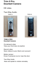
Pro
“as
©2
0
lo
go
ma
r
DB
C
AD
T
W
pert
y
of
A
D
T
is” without
w
0
17ADT LL
C
o
, 800
A
DT.
A
r
ks and/or r
e
C
835
T
Pu
l
s
e
ireles
s
Quic
T
, LLC. Info
r
w
arrant
y
of
a
C
dba ADT
S
A
SAP and t
h
eg
istered m
a
e
®
I
nt
e
DB
s
HD
k Ins
t
r
mation acc
u
a
n
y
kind.
S
ecurit
y
Ser
v
h
e product/
s
a
rks. Unau
t
r
a
c
t
i
v
C835
Door
b
t
allati
o
u
rate as of p
u
v
ices. All ri
g
s
ervice na
m
t
horized us
e
v
e
S
ol
u
b
ell C
a
o
n Gu
u
blished da
t
g
hts reserv
e
m
es listed in
t
e
is strictly p
u
t
i
on
s
a
mer
a
ide
t
e and is pro
e
d. ADT, the
t
his docum
e
rohibited.
s
a
v
ided
A
DT
e
nt are

2
C
h
I
n
Thi
s
co
m
Th
e
1.
D
2.
T
3.
W
4.
G
P
a
h
apter
1
n
trod
u
s
Chapter
p
m
ponents
a
e
following
D
oorbell
C
T
wo Moun
t
W
ood Scr
e
G
ang Box
S
a
cka
g
e
C
D
1
u
ctio
provides
d
a
nd capabi
items are
C
amera x 1
t
ing Brack
e
e
w/Anchor
S
crew x 2
C
onten
t
D
BC835
W
n
d
etails of t
h
lities.
included i
n
e
ts (Small
x 2
t
s
W
ireless Doo
h
e Doorbel
l
n
the pack
a
& One ga
n
o
rbell Cam
e
l
Camera'
s
age.
n
g-box siz
e
e
ra Installat
s
features,
e
)
i
on
1

Chapter 1: Introduction
3
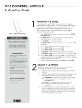
DBC835 Wireless Doorbell Camera Installation
DBC835 supports both analog and digital chime within AC 8-24 voltage.
The operation temperature is –4°F to 122°F. (–20°C to 50°C)
(The battery will not be charged when the temperature is < 0°C)
Figure 1: Front Panel
Figure 2: Rear Panel
Overview

Chapter 1: Introduction
DBC835 Wireless Doorbell Camera Installation
4
Doorbell/WPS
Button
This button has two functions:
1. WPS Pin Code Mode. When pressed and held for
0-10 seconds, the doorbell camera will be in the
WPS Pin Code mode.
Note: When WiFi connection is established, the WPS
function is disabled.
2. Doorbell. Press the button to ring the bell.
LED Behavior
z Off - No power.
z On (Blue) - Power On / Network connection is
available.
z Blinking (Green). The WPS connection is active.
z On (Red) - If the LED is on for 5 seconds and
then turns off, the WPS function has failed.
z Blinking (Red) - Network connection is failed.
z Spinning (Green). The firmware is being
upgraded.
z Intermittent Blinking (Red) – If the LED is
blinking for 2 seconds, means AC power is
disconnected.
Physical Details

2
5
DBC835 Wireless Doorbell Camera Installation
Basic Setup
This section provides information on how to assemble and
configure the DBC835 Doorbell Camera for enrollment.
1.
Power Up and check the LED
Turn on the switch on the rear side of the doorbell camera and wait for
20 seconds until the LED turns to flashing red.
Note 1: The internal battery usually could last 40 minutes of operation.
If you don’t see the camera powering up, please charge the doorbell
camera via Micro USB cable with USB charger for 2 hours before
installation.
Note 2: If the LED does not flash red, please hold the reset button for
15 seconds to factory default the camera then start the installation
process over.
Figure 3: Power LED
2.
Enroll the Camera in ADT Pulse
This process is described in
Chapter 3 ADT Pulse Enrollment
.
3.
Mount the Doorbell Camera
Mount the camera in its final permanent location. Please refer to
Chapter 4 Hardware Installation
for more details.
Installation
2

6
DBC835 Wireless Doorbell Camera Installation
ADT Pulse Enrollment
This section provides instructions for wirelessly enrolling
the
DBC835 Doorbell Camera into the ADT Pulse network.
This process
uses the Wi-Fi Protected Setup (WPS) with PIN method
to wirelessly enroll the HD Camera to the gateway via the ADT Pulse
Portal or TS Installer App.
1.
Power up the camera and wait for the LED turning flashing red, as
described in the previous chapter.
2.
Launch an Internet browser and log in to the Pulse portal or TS
installer app.
3.
Enter the
Manage Devices
screen using one of these methods:
x For the Pulse portal, select the System tab and click Manage
Devices.
x For the TS installer app, click the following Pulse Devices link:
https://portal-aries.icontrol.com/myhome/9.6.0-323/access/signin.jsp
4.
In the
Manage Devices
screen, click Cameras.
Figure 4: Clicking "Cameras" Button
Using WPS with PIN to Enroll the Doorbell Camera
3

2
Chapter 3: ADT Pulse Enrollment
7
DBC835 Wireless Doorbell Camera Installation
5.
Click the Add Using WPS button at the bottom of the screen.
Figure 5: Clicking "Add Using WPS" Button
6.
Locate the camera’s PIN number on the label on the rear of the
camera. Enter the PIN number in the WPS PIN field.
Figure 6: Entering the PIN

DBC835 Wireless Doorbell Camera Installation
Chapter 3: ADT Pulse Enrollment
8
Pu
7.
Press the Ring button, the LED would be turned to blinking green for
WPS process.
Note: This WPS process must be completed within 2 minutes or else
it will be time out. The remaining time is displayed in the upper left
portion of the screen.
8.
Click the Continue button to initiate the WPS process.
Figure 7: Clicking "Continue" Button
Figure 8: Add Camera Using WPS Screen

2
Chapter 3: ADT Pulse Enrollment
9
DBC835 Wireless Doorbell Camera Installation
9.
If the doorbell camera is enrolled, the Camera Details screen will be
displayed. Name the device and select the desired bandwidth & chimer
type. Click Save after entering all the data.
Figure 9: Saving Camera Details
10.
The newly-added device will be shown in the Cameras list, then click
Go Back at the top left of the screen.
Figure 10: Clicking Go Back Button

DBC835 Wireless Doorbell Camera Installation
Chapter 3: ADT Pulse Enrollment
10
Pu
11.
The
Manage Devices
screen is displayed. Click Close.
Figure 11: Manage Devices Screen
12.
Click "System" page to check if the device is enrolled already.
Figure 12: System Screen
13.
Move the camera to where the doorbell button is located and check
the LED to see if the camera still has WiFi connectivity.
Note: If the WiFi cannot reach the front doorbell camera, you will see
the power LED kept blinking red. Then a repeater is required or move
the CloudLink/TSS to the center of the house.

D
H
Thi
s
Do
o
1. T
2.
In
s
B
C835 Wir
e
ardw
a
s
section p
r
o
rbell Ca
m
Note:
Pulse
urn off the
Unscrew
t
recomme
n
s
tallatio
e
less Door
b
a
re I
n
r
ovides de
t
m
era.
E n s u r e t h
a
before pe
r
breaker c
F
t
he legacy
n
ded insta
l
Fi
g
n
b
ell Camer
a
n
stall
a
t
ails for wa
a
t the cam
r
manently
ircuit.
F
igure 13:
doorbell a
l
lation hei
g
g
ure 14:
M
a
Installati
o
a
tion
ll mountin
g
era is con
f
m
ounting i
t
Breaker
C
nd you wil
g
ht of the
c
M
ounting L
o
o
n
g
of the D
B
f
igured an
d
t.
C
ircuit
l find two
A
c
amera is
a
o
cation
B
C835
d
enrolled
i
A
C wires.
(
a
bout 120
~
11
n ADT
(
The
~
150cm)
4

DBC835 Wireless Doorbell Camera Installation
12
Chapter 4: Hardware Installation
3. Choose the mounting bracket to be able to cover the hole of the
legacy doorbell button.
Figure 15: Choosing Mounting Bracket
4. Use the AC wires from the existing traditional doorbell and connect the
AC wires to screw terminals of the bracket.
Figure 16: Connecting the AC Wires

D
B
5.
6.
A
d
7. T
8.
C
A
s
e
N
t
y
N
n
o
N
a
B
C835 Wir
e
Secure th
e
Note: Ins
e
A
ttach the
d
oorbell ca
m
Caution:
attach t
h
F
urn on the
C
heck if th
e
C wires a
r
e
conds.
ote 1: Ple
a
y
pe could
b
ote 2: Co
m
o
t working
N
ote 3: Ch
e
a
WiFi rep
e
e
less Doorb
e
bracket
w
e
rt the anc
h
Fig
d
oorbell c
a
m
era is fir
m
To avoid
h
e camera
F
igure 18:
A
breaker c
e
chime is
w
r
e not con
n
a
se check
b
e manag
e
m
patibility
I
properly,
e
ck WiFi s
e
ate
r
or m
o
ell Camer
a
w
ith screw
s
h
ors if nec
ure 17: In
s
a
mera to t
h
m
ly fixed
a
damaging
to the mo
u
A
ttaching
t
ircuit.
w
orking n
o
n
ected pro
p
if the sou
n
e
d in ADT
p
I
ssue of di
g
please ch
a
ignal and i
o
ve the Cl
o
Chapter 4
:
a
Installatio
n
s
. Please
s
e
ssary.
s
talling the
h
e mountin
a
nd workin
g
the rubbe
r
u
nting bra
c
t
he Came
r
o
rmally aft
e
p
erly, the
r
n
d of chim
e
p
ulse enr
o
g
ital chim
e
a
nge to
An
f the pow
e
o
udLink/T
S
:
Hardwar
e
n
s
ee Figur
e
e
Screws
g bracket.
g
properly
.
r of the po
c
ket horiz
o
r
a to the B
r
e
r pushing
r
ed LED
w
e
r works a
s
o
llment pro
e
models
a
n
alog Chi
m
e
r LED bli
n
S
S to the
c
e
Installati
o
e
17.
Make sur
e
.
g
o pin, pl
e
o
ntally.
r
acket
the Ring
b
w
ill blink ev
e
s
usual. T
h
cess.
a
nd if the c
m
er.
n
ks red, pl
e
c
enter of th
o
n
13
e
the
e
ase
b
utton. If
e
ry 5
h
e chime
himer is
e
ase add
e house.

14
DBC835 Wireless Doorbell Camera Installation
Appendix
Chime Compatibility List
Chime Compatibility List
Utilitech
Model # UT-27103-02
Utilitech
Model # UT-2735-02
Utilitech
Model # UT-7574-02
IQ America Model # DW-2403A
Hampton Bay Model # HB-7621-02
Honeywell Model# RCW102N
Honeywell Model# RCW251N
NuTone Model# LA100WH
NuTone Model# LA126WH
Heath Zenith Model# DC3360
A
7KLVGHYLFHFRPSOLHVZLWK3DUWRIWKH)&&5XOHV2SHUDWLRQLVVXEMHFWWRWKHIROORZLQJWZR
FRQGLWLRQV
WKLVGHYLFHPD\QRWFDXVHKDUPIXOLQWHUIHUHQFHDQGWKLVGHYLFHPXVWDFFHSWDQ\
LQWHUIHUHQFHUHFHLYHGLQFOXGLQJLQWHUIHUHQFHWKDWPD\FDXVHXQGHVLUHGRSHUDWLRQ
$Q\FKDQJHVRUPRGLILFDWLRQVQRWH[SUHVVO\DSSURYHGE\WKHSDUW\UHVSRQVLEOHIRUFRPSOLDQFH
FRXOGYRLGWKHDXWKRULW\WRRSHUDWHHTXLSPHQW
7KLVGHYLFHDQGLWVDQWHQQDPXVWQRWEHFRORFDWHGRURSHUDWLQJLQFRQMXQFWLRQZLWKDQ\RWKHU
DQWHQQDRUWUDQVPLWWHU
(QGXVHUVDQGLQVWDOOHUVPXVWEHSURYLGHGZLWKDQWHQQDLQVWDOODWLRQLQVWUXFWLRQVDQG
WUDQVPLWWHURSHUDWLQJFRQGLWLRQVIRUVDWLVI\LQJ5)H[SRVXUHFRPSOLDQFH
)RUSURGXFWDYDLODEOHLQWKH86$&DQDGDPDUNHWRQO\FKDQQHOaFDQEHRSHUDWHG6HOHFWLRQ
RIRWKHUFKDQQHOVLVQRWSRVVLEOH

15
DBC835 Wireless Doorbell Camera Installation
Appendix A: Chime Compatibility List
This equipment has been tested and found to comply with the limits for a Class
B digital device, pursuant to part 15 of the FCC rules. These limits are designed
to provide reasonable protection against harmful interference in a residential
installation. This equipment generates, uses and can radiate radio frequency
energy and, if not installed and used in accordance with the instructions, may
cause harmful interference to radio communications. However, there is no
guarantee that interference will not occur in a particular installation.
If this equipment does cause harmful interference to radio or television
reception, which can be determined by turning the equipment off and on, the
user is encouraged to try to correct the interference by one or more of the
following measures:
x Reorient or relocate the receiving antenna.
x Increase the separation between the equipment and receiver.
x Connect the equipment into an outlet on a circuit different from that to
which the receiver is connected.
x
C
o
ns
u
lt
t
he
d
e
a
le
r
o
r
a
n
e
x
p
e
r
i
e
nc
e
d
r
a
d
i
o
/
T
V
t
e
c
hni
c
i
a
n
f
o
r
he
lp
.
To assure continued compliance, any changes or modifications not expressly
approved by the party responsible for compliance could void the user's
authority to operate this equipment. (Example - use only shielded interface
cables when connecting to computer or peripheral devices).
RF Exposure Part
This equipment complies with FCC RF radiation exposure limits set forth for an
uncontrolled environment. This transmitter must not be co-located or
operating in conjunction with any other antenna or transmitter.
This equipment should be installed and operated with a minimum distance of
20 centimeters between the radiator and your body.
Regulatory Approvals
FCC Statement (US)

16
DBC835 Wireless Doorbell Camera Installation
Appendix A: Chime Compatibility List
This device complies with Industry Canada’s licence-exempt RSSs. Operation
is subject to the following two conditions:
(1)
This device may not cause interference; and
(2)
This device must accept any interference, including interference that may
cause undesired operation of the device.
Le présent appareil est conforme aux CNR d’Industrie Canada applicables aux
appareils radio exempts de licence. L’exploitation est autorisée aux deux
conditions suivantes :
(1)
l’appareil ne doit pas produire de brouillage ;
(2)
l’utilisateur de l’appareil doit accepter tout brouillage radioélectrique subi,
même si le brouillage est susceptible d’en compromettre le fonctionnement.
This transmitter must not be co-located or operating in conjunction with any
other antenna or transmitter. This equipment should be installed and operated
with a minimum distance of 20 centimeters between the radiator and your body.
Cet émetteur ne doit pas être Co-placé ou ne fonctionnant en même temps
qu'aucune autre antenne ou émetteur. Cet équipement devrait être installé et
actionné avec une distance minimum de 20 centimètres entre le radiateur et
votre corps.
Exposure
This device meets the exemption from the routine evaluation limits in section
2.5 of RSS102 and users can obtain Canadian information on RF exposure and
compliance.
Le dispositif rencontre l'exemption des limites courantes d'évaluation dans la
section 2.5 de RSS 102 et la conformité à l'exposition de RSS-102 rf,
utilisateurs peut obtenir l'information canadienne sur l'exposition et la
conformité de rf.
IC Statement (Canada)
/