KitchenAid KRFF507HWH Mode d'emploi
- Catégorie
- Frigos
- Taper
- Mode d'emploi

W11218735A
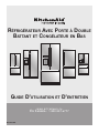
FRENCH DOOR BOTTOM MOUNT
REFRIGERATOR
USE & CARE GUIDE
WWW.KITCHENAID.COM
U.S.: 1-800-422-1230
WWW.KITCHENAID.CA
C ANADA: 1-800-807-6777

2
Congratulations on your purchase and welcome to the
KitchenAid Brand family o f high-quality appliances. Your new
KitchenAid
®
French Door Refrigerator combines advanced
cooling technology with simple operation and high efciency.
Each appliance that leave s our factory is inspected
thoroughly to ensure that it is working properly.
Please read the Use and Care Instructions in this guide
before operating your new refrigerator. Like all appliances,
your refrigerator may require maintenance or repair from
time to time, but you can help to ensure that your refrigerator
provides many years of reliable service by following the
instructions in this guide.
TABLE OF CONTENTS
REFRIGERATOR SAFETY .............................................................. 3
What’s New Behind the Doors? ................................................... 4
PARTS AND FEATURES ................................................................4
INSTALLATION INSTRUCTIONS ................................................... 5
Unpack the Refrigerator ............................................................... 5
- Remove the Packaging ..............................................................5
- Clean Before Using ....................................................................5
Location Requirements ................................................................5
Remove and Replace Refrigerator Doors .................................... 6
- Remove Right-Hand Refrigerator Door .....................................7
- Remove Left-Hand Refrigerator Door .......................................7
- Replace Right-Hand Refrigerator Door .....................................8
- Replace Left-Hand Refrigerator Door ........................................8
- Final Steps .................................................................................8
Remove and Replace Freezer Drawer Front ...............................9
- Remove Drawer Front ................................................................9
- Replace Drawer Front ................................................................9
- Final Steps .................................................................................9
Electrical Requirements .............................................................10
Water Supply Requirements ......................................................10
Connect the Water Supply .........................................................10
- Connect to Water Line .............................................................11
- Connect to Refrigerator ...........................................................11
- Complete the Installation .........................................................12
Handle Installation and Removal ...............................................12
- Install Handles ..........................................................................12
- Remove the Handles................................................................13
- Remove and Replace Handle Medallions (optional) ................13
Refrigerator Leveling, Door Closing and Alignment ..................13
FILTERS AND ACCESSORIES ....................................................15
Water Filtration System ..............................................................15
- Install the Water Filter ..............................................................15
- The Water Filter Status Light ...................................................15
- Replace the Water Filter ..........................................................16
Install Air Filter (on some models) ..............................................16
- Installing the Air Filter...............................................................16
- Installing the Filter Status Indicator .........................................16
- Replacing the Air Filter .............................................................17
Install Produce Preserver (on some models) .............................17
- Installing the Produce Preserver .............................................. 17
- Installing the Status Indicator ..................................................18
- Replacing the Produce Preserver ............................................ 18
REFRIGERATOR USE ..................................................................19
Accessories ................................................................................18
Opening and Closing Doors .......................................................19
Using the Controls .....................................................................19
- Viewing and Adjusting Temperature Set Points ......................19
- Cooling On/Off .........................................................................20
- Options .....................................................................................20
- Additional Features ..................................................................21
Water and Ice Dispensers ..........................................................22
- Flush the Water System ...........................................................22
- Calibrate Measured Fill ............................................................22
- The Water Dispenser ...............................................................23
- The Ice Dispenser ....................................................................24
- The Dispenser Drip Tray ...........................................................24
- The Dispenser Light .................................................................24
- The Dispenser Lock .................................................................24
Ice Maker and Ice Storage Bin (on some models) ....................25
- Ice Production Rate .................................................................25
- Ice Maker in the Refrigerator (on some models) .....................25
- Ice Maker in the Freezer (on some models) .............................25
REFRIGERATOR FEATURES .......................................................26
Refrigerator Shelves ...................................................................26
- Shelves and Shelf Frames .......................................................26
- Tuck Away Shelf (on some models) .........................................26
Crisper and Crisper Cover .........................................................27
Temperature-Controlled Drawer (on some models) ..................27
- Manual Control ........................................................................27
- Drawer Divider .........................................................................28
- Meat Storage Guide .................................................................28
DOOR FEATURES ........................................................................28
Door Bins ....................................................................................28
FREEZER FEATURES ..................................................................28
Pizza Pocket and Drawer Divider ..............................................28
REFRIGERATOR CARE ...............................................................29
Cleaning .....................................................................................29
- Exterior Cleaning ......................................................................29
- Interior Cleaning .......................................................................29
- Condenser Cleaning ................................................................30
Lights ..........................................................................................30
Vacation and Moving Care .........................................................30
- Vacations .................................................................................. 30
- Moving .....................................................................................30
TROUBLESHOOTING ..................................................................31
Operation ....................................................................................31
Noise ..........................................................................................32
Temperature and Moisture .........................................................33
Ice and Water .............................................................................34
Doors ..........................................................................................37
PERFORMANCE DATA SHEET ...................................................38
WARRANTY ..................................................................................39
SERVICE NUMBERS.................................................BACK COVER

3
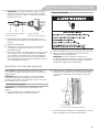
Proper Disposal of Your Old Refrigerator
IMPORTANT: Child entrapment and suffocation are not
problems of the past. Junked or abandoned refrigerators are still
dangerous—even if they will sit for “just a few days.” If you are
getting rid of your old refrigerator, please follow these instructions
to help prevent accidents.
Before You Throw Away Your Old
Refrigerator or Freezer:
■ Take off the doors.
■ Leave the shelves in place so that
children may not easily climb inside.
You can be killed or seriously injured if you don't immediately
You
can be killed or seriously injured if you don't
follow
All safety messages will tell you what the potential hazard is, tell you how to reduce the chance of injury, and tell you what can
happen if the instructions are not followed.
Your safety and the safety of others are very important.
We have provided many important safety messages in this manual and on your appliance. Always read and obey all safety
messages.
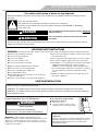
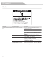
This is the safety alert symbol.
This symbol alerts you to potential hazards that can kill or hurt you and others.
All safety messages will follow the safety alert symbol and either the word “DANGER” or “WARNING.”
These words mean:
follow instructions.
instructions.
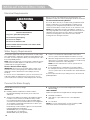
DANGER
WARNING
IMPORTANT SAFETY INSTRUCTIONS
WARNING:
To reduce the risk of fire, electric shock, or injury when using your refrigerator, follow these basic precautions:
SAVE THESE INSTRUCTIONS
■ Plug into a grounded 3 prong outlet.
■ Do not remove ground prong.
■ Do not use an adapter.
■ Do not use an extension cord.
■ Disconnect power before servicing.
■ Replace all parts and panels before operating.
■ Remove doors from your old refrigerator.
■ Connect to a potable water supply only.
■ Use nonflammable cleaner.
■ Keep flammable materials and vapors, such as gasoline,
away from refrigerator.
■ Use two or more people to move and install refrigerator.
■ Disconnect power before installing ice maker (on ice maker
kit ready models only).
■ Use a sturdy glass when dispensing ice (on some models).
■ Do not hit the refrigerator glass doors (on some models).
■ This appliance is not intended for use by persons (including
children) with reduced physical, sensory or mental
capabilities, or lack of experience and knowledge, unless
they have been given supervision or instruction concerning
use of the appliance by a person responsible for their
safety.
■ Children should be supervised to ensure that they do not
play with the appliance.
State of California Proposition 65 Warnings:
WARNING: This product contains one or more chemicals known to the State of California to cause cancer.
WARNING: This product contains one or more chemicals known to the State of California to cause birth defects or
other reproductive harm.
WARNING
Suffocation Hazard
Remove doors from your old refrigerator.
Failure to do so can result in death or brain damage.
Important information to know about disposal of
refrigerants:
Dispose of refrigerator in accordance with Federal and Local
regulations. Refrigerants must be evacuated by a licensed,
EPA certified refrigerant technician in accordance with
established procedures.
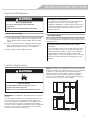
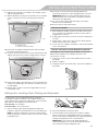
REFRIGERATOR SAFETY

4
What’s New Behind the Doors?
Your KitchenAid
®
French Door Refrigerator comes equipped with
various innovative storage and energy efcient features.
Energy and Normal Operating Sounds
Your new French Door Bottom Mount refrigerator has been
designed to optimize energy efciency, and better regulate
temperatures to match cooling demand. You may notice that it
operates differently than your previously owned refrigerator. It is
normal for the high-efciency compressor to run for extended
periods of time at varying speeds in order to consume only the
energy necessary for optimum efciency. In addition, during
various stages of the cooling cycle, you may hear normal
operating sounds that are unfamiliar to you.
More Storage Space
The French Door Bottom Mount has the most fresh food storage
space available, including a full-width, temperature controlled,
pantry drawer perfect for storing veggie trays or party platters.
In-Door-Ice
®
Ice Dispensing System
The ice storage bin located in the door provides an entire extra
shelf of storage space and the storage bin is removable for easy
access to ltered ice.
Dual Evaporator (on some models)
The refrigerator compartment and freezer compartment have
separate evaporators to provide fresh food and frozen food with
separate climates. The refrigerator stays cool and humid for the
optimum storage of fresh foods while the freezer stays cold and
dry. Humidity from the refrigerator does not mix with dry freezer
air, so frost is controlled, which reduces freezer burn. Since no air
is shared between the refrigerator and freezer, the transfer of food
odors and tastes from the refrigerator to the freezer is eliminated.
Pull Out Tray
This full-width slide-out shelf tucked between the crispers and the
lowest shelf is perfect for leftover family-sized casserole dishes,
pizza boxes, and large party platters.
Water Filter
NSF
®
Certied lter reduces chlorine taste and odor, particulates
(class I), lead, and mercury. Replacing the water lter every 6
months ensures clean, ltered drinking water.
Air Filter
An air lter is 15 times more powerful than baking soda at
reducing common food odors inside the refrigerator.
Produce Preserver (on some models)
Ethylene is a natural gas produced by fruits and vegetables to
promote ripening. The Produce Preserver absorbs ethylene, to
delay the over-ripening of fresh produce. As a result, certain
produce items will stay fresh longer.
Water Dispenser with Measured Fill
The measured ll feature allows you to dispense the desired
amount of ltered water.
LED Lighting
The LED lights do not ever need to be replaced.
Shelves with under-shelf lighting (on some models)
By moving LED lighting to a new spot under the shelves, this
leading-edge technology elevates the look and feel of your
refrigerator.
Door Alarm
A helpful alarm sounds when the refrigerator door or freezer
drawer is left ajar.
Power Outage Indicator
If the power should go out while you are away from home, this
indicator will let you know that the refrigerator has been without
power.
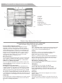
BAC
D
E
F
G
J
H
I
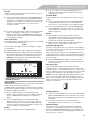
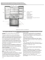
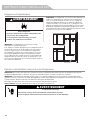
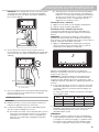
PARTS AND FEATURES
A. Ice maker
B. Air lter
C. Water lter
D. Door bins
E. Crispers
F. Pantry drawer
G. Freezer drawer
H. LED ramp-on lighting
I. In-Door-Ice
®
ice dispensing system
J. Pull Out Tray

5
Unpack the Refrigerator
Remove the Packaging
■ Remove tape and glue residue from surfaces before turning
on the refrigerator. Rub a small amount of liquid dish soap
over the adhesive with your ngers. Wipe with warm water
and dry.
■ Do not use sharp instruments, rubbing alcohol, ammable
uids, or abrasive cleaners to remove tape or glue. These
products can damage the surface of your refrigerator.
■ Dispose of/recycle all packaging materials.
Clean Before Using
After you remove all of the packaging materials, clean the inside
of your refrigerator before using it. See the cleaning instructions in
“Refrigerator Care.”
Location Requirements
IMPORTANT: This refrigerator is designed for indoor, household
use only.
To ensure proper ventilation for your refrigerator, allow for a 1/2"
(1.25 cm) of space on each side and at the top. Allow for a 1"
(2.54 cm) space behind the refrigerator. If your refrigerator has
an ice maker, allow extra space at the back for the water line
connections. When installing your refrigerator next to a xed wall,
leave a 3
3
/
4
" (9.5 cm) minimum space between the refrigerator
and wall to allow the door to swing open.
NOTE: This refrigerator is intended for use in a location where the
temperature ranges from a minimum of 55°F (13°C) to a maximum
of 110°F (43°C). The preferred room temperature range for
optimum performance, which reduces electricity usage and
provides superior cooling, is between 60°F (15°C) and 90°F
(32°C). It is recommended that you do not install the refrigerator
near a heat source, such as an oven or radiator.
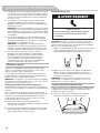
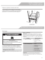
WARNING
Excessive Weight Hazard
Use two or more people to move and install
refrigerator.
Failure to do so can result in back or other injury.
When Moving Your Refrigerator:
Your refrigerator is heavy. When moving the refrigerator for
cleaning or service, be sure to cover the oor with
cardboard or hardboard to avoid oor damage. Always pull
the refrigerator straight out when moving it. Do not wiggle or
“walk” the refrigerator when trying to move it, as oor
damage could occur.
Important information to know about glass shelves
and covers:
Do not clean glass shelves or covers with warm water when
they are cold. Shelves and covers may break if exposed to
sudden temperature changes or impact, such as bumping.
Tempered glass is designed to shatter into many small,
pebble-size pieces. This is normal. Glass shelves and covers
are heavy. Use both hands when removing them to avoid
dropping.
WARNING
Explosion Hazard
Keep ammable materials and vapors, such as
gasoline, away from refrigerator.
Failure to do so can result in death, explosion, or re.
3³⁄₄" (9.5 cm)
¹⁄₂" (1.25 cm)
INSTALLATION INSTRUCTIONS

6
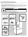
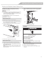
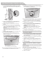
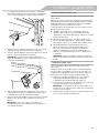
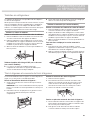
Remove and Replace Refrigerator Doors
NOTE: Measure the width of your door opening, to see whether or not you need to remove the refrigerator doors to move the refrigerator
into your home. If door removal is necessary, see the following instructions.
IMPORTANT: If the refrigerator was previously installed and you are moving it out of the home, before you begin, turn the refrigerator
control OFF. Unplug the refrigerator or disconnect power. Remove food and adjustable door or utility bins from doors.
Gather the required tools and read all instructions before removing doors.
TOOLS NEEDED: 3/16" hex- key wrench and a #2 Phillips screwdriver
WARNING
Electrical Shock Hazard
Disconnect power before removing doors.
Failure to do so can result in death or electrical shock.
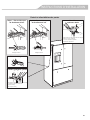
A
BA
C
A
C
B
A
D
INSTALLATION INSTRUCTIONS
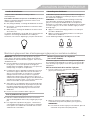
Door Removal and Replacement
Style 1 – Water Dispenser
Tubing Connection
Style 1 – Water Dispenser
Tubing Connection
Top Right Hinge
Wiring Plug
Top Left Hinge
A. Outer Ring A. Outer Ring
A. 3/16" Internal hex-head Screws
B. Hinge Cover Screw
C. Top Hinge Cover
D. Top Hinge
A. 3/16" Internal hex-head Screws
B. Ground Wire (Do Not Remove)
C. Screws (Do Not Remove)

7
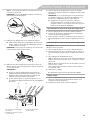
Remove Right-Hand Refrigerator Door
1. Unplug refrigerator or disconnect power.
2. Keep the refrigerator doors closed until you are ready to lift
them free from the cabinet.
NOTE: Provide additional support for the refrigerator door
while the hinges are being removed. Do not depend on the
door gasket magnets to hold the door in place while you are
working.
3. Using a Phillips screwdriver, remove the cover from the Top
Hinge.
4. Using the 3/16" hex-key wrench, remove the two internal hex-
head screws from the top hinge, and set aside.
NOTE: Do not remove the two locator screws. These screws
will help you align the hinge when you replace the door.
5. Lift the refrigerator door from the bottom hinge pin. The top
hinge will come away with the door.
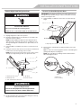
Remove Left-Hand Refrigerator Door
IMPORTANT: The tubing and wiring for the water dispenser run
through the left-hand door hinge, so they must be disconnected
before removing the door.
1. Using a Phillips screwdriver, remove the cover from the top
hinge.
2. Disconnect the water dispenser tubing located on top of the
door hinge.
Style 1 - Press the outer ring against the face of the tting and
gently pull the dispenser tubing free.
NOTE: The water dispenser tubing remains attached to the
left-hand refrigerator door.
WARNING
Electrical Shock Hazard
Disconnect power before removing doors.
Failure to do so can result in death or electrical shock.
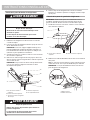
A
B
E
C
D
A. Top hinge cover screw
B. Top hinge cover
C. 3/16" Internal hex-head screws
D. Top Hinge
E. Locator Screws
WARNING
Excessive Weight Hazard
Use two or more people to lift the refrigerator door.
Failure to do so can result in back or other injury.
A
B
A. Top hinge cover screw B. Top hinge cover
AB
A. Outer ring
B. Face of tting
INSTALLATION INSTRUCTIONS

8
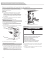
Style 2 - Firmly pull up on the clasp. Then, pull the tubing out
of the tting.
NOTE: The water dispenser tubing remains attached to the
left-hand refrigerator door.
3. Disconnect the wiring plug located on top of the door hinge.
■ Grasp each side of the wiring plug. With your left thumb,
press down to release the catch and pull the sections of
the plug apart.
NOTE: Do not remove the green, ground wire. It should
remain attached to the door hinge.
4. Using the 3/16" hex-key wrench, remove the two internal hex-
head screws from the top hinge, and set aside.
NOTES:
■ Provide additional support for the refrigerator door while
the hinges are being removed. Do not depend on the door
gasket magnets to hold the door in place while you are
working.
■ Do not remove the two locator screws. These screws will
help you align the hinge when you replace the door.
5. Lift the refrigerator door from the bottom hinge pin. The top
hinge will come away with the door.
NOTE: It may not be necessary to remove the bottom hinges
and brake feet assemblies to move the refrigerator through a
doorway.
■ Only if necessary, use a driver with a #2 square bit tip to
remove the bottom hinges and a 3/8" nut driver to remove
the brake feet screws.
Replace Right-Hand Refrigerator Door
1. Set the right-hand door onto the bottom hinge pin.
2. Insert the top hinge pin into the open hole in the top of the
refrigerator door.
3. Using the two 3/16" internal hex-head screws, fasten the
hinge to the cabinet. Do not tighten the screws completely.
Replace Left-Hand Refrigerator Door
IMPORTANT: Do not intertwine the water tubing and wiring
bundles when reconnecting them.
1. Set the left-hand door onto the bottom hinge pin.
2. Using the two 3/16" internal hex-head screws, fasten the
hinge to the cabinet. Do not tighten the screws completely.
3. Reconnect the water dispenser tubing.
Style 1 - Insert the tubing into the tting until it stops and the
outer ring is touching the face of tting.
Style 2 - Insert the tubing rmly into the tting until it stops.
Close the clasp around the tubing. The clasp snaps into place
between the tting and the collar.
4. Reconnect the electrical wiring.
■ Push together the two sections of the wiring plug.
Final Steps
1. Completely tighten the four internal hex-head screws (two
on the right-hand door hinge and two on the left-hand door
hinge).
2. Replace both top hinge covers.
A B
C
A. 3/16" Internal hex-head screws
B. Ground wire (do not remove)
C. Locator screws (do not remove)
INSTALLATION INSTRUCTIONS

9
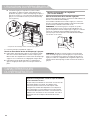
Remove and Replace Freezer Drawer Front
Depending on the width of your door opening, it may be
necessary to remove the freezer drawer front to move the
refrigerator into your home.
IMPORTANT:
■ If the refrigerator was previously installed and you are moving
it out of the home, before you begin, turn the refrigerator
control OFF, and unplug the refrigerator or disconnect power.
Remove food from the freezer drawer.
■ Two people may be required to remove and replace the
freezer drawer front.
Tool Needed: 1/4" hex driver
Remove Drawer Front
1. Open the freezer drawer to its full extension.
2. Remove the two screws at the top, inside the drawer front
(one on the left-hand side and one on the right-hand side) that
fasten the drawer front to the drawer glides.
3. Lift up on the drawer front to release the plastic studs from
the drawer glide bracket slots.
4. Slide the drawer glides back into the freezer.
Replace Drawer Front
1. Pull out the freezer drawer glides to their full extension.
2. Holding the drawer front by its sides, align the two plastic
studs, located at the bottom, inside the drawer front, with the
drawer glide bracket slots.
NOTE: It helps if one person holds the drawer glides steady
while another person aligns the drawer front and inserts the
studs into the slots.
3. Replace and tighten the two screws at the top of the drawer
front (one on the left-hand side and one on the right-hand
side).
Final Steps
1. Plug into a grounded 3 prong outlet.
2. Reset the controls. See “Using the Controls.”
3. Return all removable door parts to doors and the food to
refrigerator.
A
A. Drawer glide bracket slots
A
B
A. Drawer front screw
B. Drawer front plastic stud
Electrical Shock Hazard
Plug into a grounded 3 prong outlet.
Do not remove ground prong.
Do not use an adapter.
Do not use an extension cord.
Failure to follow these instructions can result in death,
fire, or electrical shock.
WARNING
INSTALLATION INSTRUCTIONS

10
Electrical Requirements
Before you move your refrigerator into its nal location, it is
important to make sure you have the proper electrical connection.
Recommended Grounding Method
A 115 volt, 60 Hz, AC only 15 or 20 A fused, grounded electrical
supply is required. It is recommended that a separate circuit
serving only your refrigerator be provided. Use an outlet that
cannot be turned off by a switch. Do not use an extension cord.
NOTE: Before performing any type of installation, cleaning, or
removing a light bulb, turn Cooling OFF, and then disconnect the
refrigerator from the electrical source. When you have nished,
reconnect the refrigerator to the electrical source and turn
Cooling ON. See “Using the Controls.”
Water Supply Requirements
A cold water supply with water pressure between 35 and 120 psi
(241 and 827 kPa) is required to operate the water dispenser and
ice maker. If you have questions about your water pressure, call a
licensed, qualied plumber.
NOTE: If the water pressure is less than what is required, the ow
of water from the water dispenser could decrease or ice cubes
could be hollow or irregular shaped.
Reverse Osmosis Water Supply
IMPORTANT: The pressure of the water supply coming out of
a reverse osmosis system going to the water inlet valve of the
refrigerator needs to be between 35 and 120 psi (241 and
827 kPa).
If a reverse osmosis water ltration system is connected to your
cold water supply, the water pressure to the reverse osmosis
system needs to be a minimum of 40 to 60 psi (276 to 414 kPa).
■ Check to see whether the sediment lter in the reverse
osmosis system is blocked. Replace the lter if necessary.
■ Allow the storage tank on the reverse osmosis system to rell
after heavy use. The tank capacity could be too small to keep
up with the requirements of the refrigerator.
NOTE: Faucet mounted reverse osmosis systems are not
recommended.
■ If your refrigerator has a water lter, it may further reduce
the water pressure when used in conjunction with a reverse
osmosis system. Remove the water lter. See “Water Filtration
System.”
If you have questions about your water pressure, call a licensed,
qualied plumber.
Connect the Water Supply
Read all directions before you begin.
IMPORTANT:
■ Plumbing shall be installed in accordance with the
International Plumbing Code and any local codes and
ordinances.
■ The gray water tubing on the back of the refrigerator (which
is used to connect to the household water line) is a PEX
(cross-linked polyethylene) tube. Copper and PEX tubing
connections from the household water line to the refrigerator
are acceptable, and will help avoid off-taste or odor in your
ice or water. Check for leaks.
If PEX tubing is used instead of copper, we recommend the
following Whirlpool Part Numbers:
W10505928RP (7 ft [2.14 m] jacketed PEX),
8212547RP (5 ft [1.52 m] PEX), or
W10267701RP (25 ft [7.62 m] PEX).
■ Install tubing only in areas where temperatures will remain
above freezing.
TOOLS NEEDED:
Gather the required tools and parts before starting installation.
■ Flat-blade screwdriver
■ 7⁄16" and 1/2" open-end wrenches or two adjustable
wrenches
■ 1/4" nut driver
NOTE: Do not use a piercing-type or 3/16" (4.76 mm) saddle
valve which reduces water ow and clogs easier.
Electrical Shock Hazard
Plug into a grounded 3 prong outlet.
Do not remove ground prong.
Do not use an adapter.
Do not use an extension cord.
Failure to follow these instructions can result in death,
fire, or electrical shock.
WARNING
INSTALLATION INSTRUCTIONS

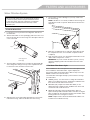
11
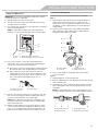
Connect to Water Line
IMPORTANT: If you turn the refrigerator on before the water is
connected, turn the ice maker OFF.
1. Unplug refrigerator or disconnect power.
2. Turn OFF main water supply. Turn ON nearest faucet long
enough to clear line of water.
3. Use a quarter-turn shutoff valve or the equivalent, served by a
1/2" household supply line.
NOTE: To allow sufcient water ow to the refrigerator, a
minimum 1/2" size household supply line is recommended.
4. Now you are ready to connect the copper tubing to the
shutoff valve. Use 1/4" (6.35 mm) OD soft copper tubing to
connect the shutoff valve and the refrigerator.
■ Ensure that you have the proper length needed for the job.
Be sure both ends of the copper tubing are cut square.
■ Slip compression sleeve and compression nut onto
copper tubing as shown. Insert end of tubing into outlet
end squarely as far as it will go. Screw compression nut
onto outlet end with adjustable wrench. Do not
overtighten.
5. Place the free end of the tubing into a container or sink, and
turn on main water supply to ush out tubing until water is
clear. Turn OFF shutoff valve on the water pipe.
NOTE: Always drain the water line before making the nal
connection to the inlet of the water valve to avoid possible
water valve malfunction.
6. Bend the copper tubing to meet the water line inlet, which
is located on the back of the refrigerator cabinet as shown.
Leave a coil of copper tubing to allow the refrigerator to be
pulled out of the cabinet or away from the wall for service.
Connect to Refrigerator
Follow the connection instructions specic to your model.
Style 1
1. Remove plastic cap from water valve inlet port. Attach the
copper tube to the valve inlet using a compression nut
and sleeve as shown. Tighten the compression nut. Do not
overtighten. Conrm copper tubing is secure by pulling on
copper tubing.
2. Create a service loop with the copper tubing. Avoid kinks
when coiling the copper tubing. Secure copper tubing to
refrigerator cabinet with a “P” clamp.
3. Turn on water supply to refrigerator and check for leaks.
Correct any leaks.
Style 2
1. Unplug refrigerator or disconnect power.
2. Remove and discard the short, black plastic part from the end
of the water line inlet.
3. Thread the nut onto the end of the tubing. Tighten the nut by
hand. Then tighten it with a wrench two more turns. Do not
overtighten.
NOTE: To avoid rattling, be sure the copper tubing does not
touch the cabinet’s side wall or other parts inside the cabinet.
A
B
D
C
A. Sleeve
B. Nut
C. Copper tubing (to refrigerator)
D. Household supply line (1/2" minimum)
B CA
A. Compression sleeve
B. Compression nut
C. Copper tubing
B
A
C
D
A. Copper tubing
B. “P” clamp
C. Compression nut
D. Compression sleeve
D
A B C
A. Household water line
B. Nut (purchased)
C. Ferrule (purchased)
D. Refrigerator water tubing
INSTALLATION INSTRUCTIONS

12
4. Install the water supply tube clamp around the water supply
line to reduce strain on the coupling.
5. Turn shutoff valve ON.
6. Check for leaks. Tighten any connections (including
connections at the valve) or nuts that leak.
7. On some models, the ice maker is equipped with a built-in
water strainer. If your water conditions require a second water
strainer, install it in the 1/4" (6.35 mm) water line at either
tube connection. Obtain a water strainer from your appliance
dealer.
Complete the Installation
1. Plug into a grounded 3 prong outlet.
2. Flush the water system. See “Water and Ice Dispensers.”
NOTE: Allow 24 hours to produce the rst batch of ice.
Discard the rst three batches of ice produced. Allow 3 days
to completely ll the ice storage bin.
Handle Installation and Removal
Parts Included: Door handles (2), Drawer handle(s) (1 or 2
depending on model), 1/8" hex key, spare setscrew(s)
NOTE: With the handles laying on a at surface, the handles
intended for the drawers are more curved. They will not mount
ush against the doors.
Install Handles
NOTE: Handle mounting setscrews are preinstalled inside the
handle.
1. Remove the handles from the packaging inside the
refrigerator, and place them on a soft surface.
2. Open a refrigerator compartment door. On the closed door,
place a handle onto the shoulder screws so that the
setscrews are facing the adjacent door.
3. Firmly push the handle toward the door until the handle base
is ush against the door.
4. While holding the handle, insert the short end of the hex key
into the upper hole and slightly rotate the hex key until it is
engaged in the setscrew.
5. Using a clockwise motion tighten the setscrew just until it
begins to contact the shoulder screw. Do not fully tighten.
6. Repeat steps 4 and 5 to fasten the lower setscrew.
7. Once both setscrews have been partially tightened as
instructed in the previous steps, fully tighten both setscrews.
IMPORTANT: When the screws feel tight, tighten them an
additional quarter-turn. The handle is not properly installed
without this extra tightening.
Electrical Shock Hazard
Plug into a grounded 3 prong outlet.
Do not remove ground prong.
Do not use an adapter.
Do not use an extension cord.
Failure to follow these instructions can result in death,
fire, or electrical shock.
WARNING
A
B
A. Shoulder screws
B. Setscrews inside the handle
INSTALLATION INSTRUCTIONS

13
8. Repeat steps 2 through 7 to install the other handle onto the
adjacent refrigerator door.
9. With the drawer(s) closed, place the handle onto the shoulder
screws so that the setscrews are facing down toward the
oor.
10. Firmly push the handle toward the drawer until the handle
base is ush against the drawer.
11. Insert the short end of the hex key into the left-hand hole and
slightly rotate the hex key until it is engaged in the setscrew.
12. Using a left to right motion tighten the setscrew a quarter-turn
at a time just until it begins to contact the shoulder screw. Do
not fully tighten.
13. Repeat steps 11 and 12 to fasten the right-hand setscrew to
the shoulder screw.
14. Once both setscrews have been partially tightened as
instructed in the previous steps, fully tighten both setscrews.
IMPORTANT: When the screws feel tight, tighten them an
additional quarter-turn. The handle is not properly installed
without this extra tightening.
15. For some models, repeat steps 9 through 14 to install a
handle on the second drawer.
16. Save the hex key and all instructions.
Remove the Handles
1. While holding the handle, insert the short end of the hex key
into a setscrew hole and slightly rotate the hex key until it is
engaged in the setscrew.
2. Using a right to left motion loosen the setscrew a quarter-turn
at a time.
3. Repeat steps 1 and 2 for the other setscrew. Slowly pull the
handle away from the door or drawer.
4. If necessary, use a Phillips screwdriver to remove the shoulder
screws from the door.
Remove and Replace Handle Medallions (optional)
The handles for your model have red medallions on the ends.
Replacement medallions are available for purchase. See
“Accessories” to order.
1. Using a 1/8" hex key, remove the medallion from the end of
the handle.
2. Replace medallion.
3. Using the fastener removed in Step 1, attach the medallion to
the handle.
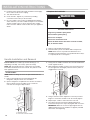
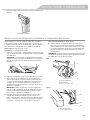
Refrigerator Leveling, Door Closing and Alignment
The base grille covers the adjustable brake feet and roller
assemblies located at the bottom of the refrigerator below the
freezer drawer. Before making any adjustments, remove the base
grille and move the refrigerator to its nal location.
Tools Needed: 1/4" hex driver
Tools Provided: 1/8" hex-key wrench
1. Remove the base grille. Grasp the grille rmly and pull it
toward you. Open the freezer drawer to access the brake feet.
NOTE: To allow the refrigerator to roll easier, raise the break
feet by turning them counterclockwise. The front rollers will be
touching the oor.
2. Move the refrigerator to its nal location.
3. Lower the brake feet, by turning them clockwise, until the
rollers are off the oor and both brake feet are snug against
the oor. This keeps the refrigerator from rolling forward when
opening the refrigerator doors or freezer drawer.
IMPORTANT: If you need to make further adjustments
involving the brake feet, you must turn both brake feet the
same amount to keep the refrigerator level.
A
B
A. Shoulder screw
B. Setscrews inside the handle
A
A. Handle medallion
INSTALLATION INSTRUCTIONS

14
4. Make sure the doors close easily. If you are satised with the
door opening and closing, skip the next section and go to
“Align the Doors.” If, however, the doors do not close easily or
the doors pop open, adjust the tilt.
To Adjust the Cabinet Tilt:
■ Open the freezer drawer. Use a 1/4" hex driver to turn
both brake feet clockwise the same amount. This will raise
the front of the refrigerator. It may take several turns to
allow the doors to close easier.
NOTE: Having someone push against the top of the
refrigerator takes some weight off the brake feet. This makes
it easier to turn them.
Style 1
Style 2
5. Make sure the doors are even at the top and that the space
between the bottom of the refrigerator doors and the top of
the freezer drawer is even. If necessary, align the doors.
To Align the Doors:
■ Keeping both refrigerator doors closed, pull out the freezer
drawer. Locate the bottom hinge pin of the right-hand
refrigerator door. The alignment screw is inside the bottom
hinge pin.
■ Insert the short end of the 1/8" hex- key wrench (packed
with the Door Handle Installation Instructions) into the
bottom hinge pin until it is fully engaged in the alignment
screw.
To raise the refrigerator door, turn the hex key to the right.
To lower the door, turn the hex key to the left.
■ Continue to turn the alignment screw until the doors are
aligned.
6. Make sure the refrigerator is steady. If the refrigerator seems
unsteady or rolls forward when the door or drawer is pulled
open, adjust the brake feet.
To Steady the Refrigerator:
■ Open the freezer drawer. Using a 1/4" hex driver, turn both
brake feet clockwise the same amount until the brake feet
are snug against the oor. Check again. If not satised,
continue to adjust the brake feet by half turns of the screw
until the refrigerator does not roll forward when the drawer
is opened.
NOTE: Having someone push against the top of the
refrigerator takes some weight off the brake feet. This makes
it easier to turn the screws.
7. Replace the base grille by aligning the ends of the grille with
the leveling assemblies on each side and snapping the grille
into place.
A
C
B
A. Brake foot
B. Front roller
C. 1/4" Hex driver
A
B
A. Brake foot
B. 1/4" Hex driver
A
B
A. Bottom hinge pin
B. 1/8" Hex-key wrench
INSTALLATION INSTRUCTIONS

15
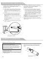
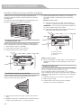
Water Filtration System
Install the Water Filter
1. Locate the accessory packet in the refrigerator and remove
the water lter.
2. Take the water lter out of its packaging and remove the cover
from the O-rings. Be sure the O-rings are still in place after the
cover is removed.
3. The water lter compartment is located in the right-hand side
of the refrigerator ceiling. Push up on the compartment door
to release the catch, and then lower the door.
4. Align the arrow on the water lter label with the cutout notch
in the lter housing, and insert the lter into the housing.
5. Turn the lter clockwise 90 degrees (1/4 turn), until it locks
into the housing.
NOTE: If the lter is not correctly locked into the housing, the
water dispenser will not operate. Water will not ow from the
dispenser.
6. While the compartment door is still open, lift the lter up into
the compartment. Then, close the lter compartment door
completely.
7. Flush the water system. See “Flushing the Water Filter” in the
“Water and Ice Dispensers” section.
IMPORTANT: If you do not ush the water system, you may
experience dripping and/or decreased ow from the water
dispenser.
The Water Filter Status Light
Press OPTIONS on the control panel to launch the Options menu.
Press OPTIONS, under Filter Status, again to display the
percentage of lter life remaining (from 100% to 0%). Press ICE
MODE to return to the Normal screen.
The water lter status lights will help you know when to change
your water lter.
■ ORDER (yellow) - it is almost time to change the water lter.
While you are dispensing water, “Order Filter” will blink seven
times and sound an alert tone three times.
■ REPLACE (red) - Replace the water lter. While you are
dispensing water, “Replace Filter” will blink seven times and
an alert tone will sound three times.
■ RESET the water lter status tracking feature. After you
replace the disposable water lter with a new lter, closing the
lter compartment door will automatically reset the lter status
tracking feature. See “Using the Controls.”
NOTE: “Replace Filter” will remain illuminated if a lter is not
installed or is installed incorrectly.
Do not use with water that is microbiologically unsafe or
of unknown quality without adequate disinfection before
or after the system. Systems certified for cyst reduction
may be used on disinfected waters that may contain
filterable cysts.
B
A
A. O-ring cover
B. O-rings
FILTERS AND ACCESSORIES

16
Replace the Water Filter
To purchase a replacement water lter, see “Accessories.”
Replace the disposable water lter when indicated on the water
lter status display or at least every 6 months. If water ow to
your dispenser or ice maker decreases noticeably, change the
water lter sooner.
1. Locate the water lter compartment in the right-hand side
of the refrigerator ceiling. Push up to release and lower the
compartment door.
2. Turn the water lter counterclockwise (to the left), and pull it
straight out of the compartment.
NOTE: There may be some water in the lter. Some spilling
may occur. Use a towel to wipe up any spills.
3. Install the replacement water lter by following steps 2
through 7 in the “Install the Water Filter” section.
Install Air Filter (on some models)
An air lter is 15 times more powerful than baking soda at
reducing common food odors inside the refrigerator.
Your refrigerator's accessory packet includes an air lter, which
must be installed prior to use.
Installing the Air Filter
Install the air lter behind the vented door, located on the rear wall
near the top of the refrigerator compartment.
1. Remove the air lter from its packaging.
2. Lift open the vented door.
3. Snap the lter into place.
Installing the Filter Status Indicator
The lter comes with a status indicator, which should be activated
and installed at the same time the air lter is installed.
1. Place the indicator face-down on a rm, at surface.
2. Apply pressure to the bubble on the back of the indicator until
the bubble pops to activate the indicator.
3. Lift open the vented air lter door. On some models, there are
notches behind the door.
Models with notches:
■ With the indicator screen facing outward, slide the
indicator down into the notches.
NOTE: The indicator will not easily slide into the notches if the
bubble has not been popped.
■ Close the air lter door, and check that the indicator is
visible through the window in the door.
A
A. Air lter
B
A
C
A. Status indicator window
B. Air lter status indicator
C. Notches
FILTERS AND ACCESSORIES

17
Models without notches:
■ Place the indicator somewhere it is easily visible — either
inside the refrigerator, or elsewhere in your kitchen or home.
Replacing the Air Filter
The disposable air lter should be replaced every 6 months when
the status indicator has completely changed from white to red.
To order a replacement air lter, contact us. See “Accessories”
in the User Guide, Use and Care Guide or User Instructions for
information on ordering.
1. Remove the used air lter by squeezing in on the side tabs.
2. Remove the used status indicator.
3. Install the new air lter and lter status indicator using the
instructions in the previous sections.
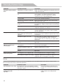
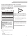
Install Produce Preserver (on some models)
The Produce Preserver absorbs ethylene to slow the ripening
process of many produce items. As a result, certain produce
items will stay fresh longer.
Ethylene production and sensitivity varies depending on the type
of fruit or vegetable. To preserve freshness, it is best to separate
produce with sensitivity to ethylene from fruits that produce
moderate to high amounts of ethylene.
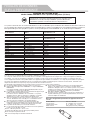
Sensitivity to
Ethylene
Ethylene
Production
Apples High Very High
Asparagus Med. Very Low
Berries Low Low
Broccoli High Very Low
Cantaloupe Med. High
Carrots Low Very Low
Citrus Fruit Med. Very Low
Grapes Low Very Low
Lettuce High Very Low
Pears High Very High
Spinach High Very Low
Installing the Produce Preserver
1. Find the Produce Preserver housing inside the refrigerator.
2. Open the housing by pulling up and out on the back.
3. Remove the Produce Preserver pouches from the packaging
and place them into the housing.
NOTE: For best performance, always use two pouches.
4. Adhere the Produce Preserver housing to the back wall of the
crisper drawer according to the instructions included in the
package.
CAUTION: IRRITANT
MAY IRRITATE EYES AND SKIN. DANGEROUS FUMES
FORM WHEN MIXED WITH OTHER PRODUCTS.
Do not mix with cleaning products containing ammonia,
bleach or acids. Do not get in eyes, on skin or clothing. Do
not breathe dust. Keep out of reach of children.
FIRST AID TREATMENT: Contains potassium
permanganate. If swallowed, call a Poison Control Center or
doctor immediately. Do not induce vomiting. If in eyes, rinse
with water for 15 minutes. If on skin, rinse with water.
FILTERS AND ACCESSORIES

18
Installing the Status Indicator
The produce preserver comes with a status indicator, which
should be activated and installed at the same time the pouches
are installed.
1. Place the indicator face-down on a rm, at surface.
2. Apply pressure to the bubble on the back of the indicator until
the bubble pops, to activate the indicator.
3. Slide open the cap on the top of the produce preserver
housing.
4. Place the indicator in the top of the housing, facing outward.
5. Slide the cap closed, and check that the indicator is visible
through the rectangular hole in the cap.
NOTE: The cap will not easily close if the indicator’s bubble
has not been popped.
Replacing the Produce Preserver
The disposable pouches should be replaced every 6 months or
when the status indicator changes completely from white to red.
To order replacements, contact us. See “Accessories” for
information on ordering.
1. Remove the used pouches from the produce preserver
housing.
2. Remove the used status indicator.
3. Install the replacement pouches and status indicator using
the instructions in the previous sections.
Accessories
The following accessories are available for your refrigerator. To
order an accessory, contact us and ask for the part number.
In the U.S.A., visit our webpage www.kitchenaid.com/
accessories or call 1-800-901-2042.
In Canada, visit our webpage www.kitchenaid.ca
or call 1-800-807-6777.
Affresh
®
Stainless Steel Cleaner:
In U.S.A., order Part #W10355016
In Canada, order Part #W10355016B
Affresh
®
Stainless Steel Wipes:
In U.S.A., order Part #W10355049
In Canada, order Part #W10355049B
Affresh
®
Kitchen & Appliance Cleaner:
In U.S.A., order Part #W10355010
In Canada, order Part #W10355010B
Water Filter:
Order Part #W10413645A or FILTER2
Air Filter:
Order Part #W10311524 or AIR1
Produce Preserver:
Order Part # W10346771A or FRESH1
Produce Preserver Starter Kit:
Order Part # P1UB6S1
Produce Preserver Rell Kit:
Order Part # P1KC6R1
Water Filter, Air Filter and Produce Preserver Bundle Pack:
Order Part # W10413643BL
Door Handle Medallions:
Order Part #W10762987 (Black)
Order Part #W10762993 (Chrome)
FILTERS AND ACCESSORIES

19
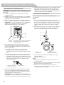
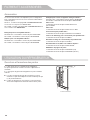
Opening and Closing Doors
There are two refrigerator compartment doors. The doors can be
opened and closed either separately or together.
There is a vertically-hinged seal on the left refrigerator door.
■ When the left side door is opened, the hinged seal
automatically folds inward so that it is out of the way.
■ When both doors are closed, the hinged seal automatically
forms a seal between the two doors.
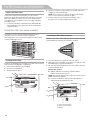
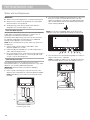
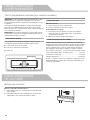
Using the Controls
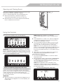
The controls are located above the external dispenser.
IMPORTANT: The display screen on the dispenser control panel
will turn off automatically and enter Sleep mode when the control
buttons and dispenser paddles have not been used for 2 minutes
or more. Press any control button to reactivate the display screen.
The home screen will appear as shown.
Viewing and Adjusting Temperature Set Points
For your convenience, your refrigerator and freezer temperature
controls are set to the recommended set points at the factory.
When you rst install your refrigerator, make sure the temperature
controls are still set to the recommended set points. The
recommended set points are 37°F (3°C) for the refrigerator and
0°F (-18°C) for the freezer.
IMPORTANT:
■ Wait 24 hours before you put food into the refrigerator. If you
add food before the refrigerator has cooled completely, your
food may spoil.
NOTE: Adjusting the set points to a colder than
recommended setting will not cool the compartments any
faster.
■ If the temperature is too warm or too cold in the refrigerator
or freezer, rst check the air vents to be sure they are not
blocked before adjusting the controls.
■ The recommended set points should be correct for normal
household use. The controls are set correctly when milk or
juice is as cold as you like and when ice cream is rm.
NOTE: Areas such as a garage or porch may experience
hotter or colder temperatures and higher humidity than inside
the home. You may need to adjust the temperature away
from the recommended set points to accommodate for these
conditions.
■ Wait at least 24 hours between adjustments. Recheck the
temperatures before other adjustments are made.
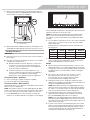
View Temperature Set Points
1. Press and hold TEMPERATURE for 3 seconds to activate
Temperature mode.
2. When Temperature mode is activated, press TEMPERATURE
to toggle between the Refrigerator zone and the Freezer
zone. The display will show the temperature set point of the
selected compartment, as shown.
NOTE: When Temperature mode is activated, to view
temperatures in degrees Celsius, press the LIGHT button,
under Units. To return the display setting to Fahrenheit, press
the LIGHT button again.
Recommended Refrigerator Temperature
A
A. Hinged seal
REFRIGERATOR USE

20
Recommended Freezer Temperature
Adjust Temperature Set Points
Refrigerator set point range: 33°F to 45°F (0°C to 7°C).
Freezer set point range: -5°F to 5°F (-21°C to -15°C).
1. Press and hold TEMPERATURE for 3 seconds to activate
Temperature mode.
2. When Temperature mode is activated, press TEMPERATURE
to select the Refrigerator zone. The display will show the
temperature set point of the selected compartment as shown.
3. Press LOCK, under plus, to raise the set point, or press
OPTIONS, under minus, to lower the set point.
4. When you have nished adjusting the refrigerator set point,
press TEMPERATURE to change the display to show
the freezer set point. When the zone has been changed,
“FREEZER” appears on the display screen.
5. Press LOCK, under the plus button, to raise the set point,
or press OPTIONS, under the minus button, to lower the set
point.
Save/Conrm Temperature Settings
■ When you have nished adjusting both the refrigerator and
freezer set points, press MEASURED FILL “Conrm” to save
the settings.
NOTE: To exit Temperature mode without saving changes, press
the ICE MODE button under Back at any time, or allow about
60 seconds of inactivity. The temperature mode will turn off
automatically and return to the normal screen.
When adjusting temperature set points,
use the following chart as a guide:
CONDITION: TEMPERATURE
ADJUSTMENT:
REFRIGERATOR too cold REFRIGERATOR Setting 1°
higher
REFRIGERATOR too warm REFRIGERATOR Setting 1°
lower
FREEZER too cold FREEZER Setting
1° higher
FREEZER too warm /
Too little ice
FREEZER Setting
1° lower
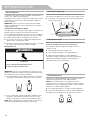
Cooling On/Off
Your refrigerator and freezer will not cool when cooling is turned
off.
■ To turn cooling off, press and hold the LOCK and MEASURED
FILL buttons at the same time for 3 seconds. When cooling
is off, “Refrigeration Cooling is Off” will appear on the display
screen as shown.
IMPORTANT: To avoid unintentionally locking the dispenser
or changing other settings, be sure to press both buttons at
exactly the same time.
■ To turn cooling back on, press and hold LOCK and
MEASURED FILL for 3 seconds again. COOLING IS OFF will
disappear from the display screen.
Options
Press the OPTIONS button to open the Options menu and select
between Max Cool, Max Ice and Water Filter Status.
Press the ICE MODE button at any time to return to the normal
screen.
Max Cool
The Max Cool feature assists with periods of high refrigerator use,
full grocery loads, or temporarily warm room temperatures.
■ To turn on the Max Cool feature, press the OPTIONS button to
enter Options mode, then press the LOCK button, under Max
Cool, to activate the feature. When the feature is on, the Max
Cool icon will appear on the dispenser display screen. The
Max Cool feature will remain on for 24 hours unless manually
turned off.
■ To manually turn off the Max Cool feature, press the OPTIONS
button to enter Options mode (unless you are already in
Options mode), then press LOCK again. When the feature has
been turned off, the Max Cool icon will disappear from the
dispenser display.
NOTE: Setting the freezer to a colder temperature may make
some foods, such as ice cream, harder.
A
A. Press LOCK and MEASURED FILL at the same time.
REFRIGERATOR USE
La page charge ...
La page charge ...
La page charge ...
La page charge ...
La page charge ...
La page charge ...
La page charge ...
La page charge ...
La page charge ...
La page charge ...
La page charge ...
La page charge ...
La page charge ...
La page charge ...
La page charge ...
La page charge ...
La page charge ...
La page charge ...
La page charge ...
La page charge ...
La page charge ...
La page charge ...
La page charge ...
La page charge ...
La page charge ...
La page charge ...
La page charge ...
La page charge ...
La page charge ...
La page charge ...
La page charge ...
La page charge ...
La page charge ...
La page charge ...
La page charge ...
La page charge ...
La page charge ...
La page charge ...
La page charge ...
La page charge ...
La page charge ...
La page charge ...
La page charge ...
La page charge ...
La page charge ...
La page charge ...
La page charge ...
La page charge ...
La page charge ...
La page charge ...
La page charge ...
La page charge ...
La page charge ...
La page charge ...
La page charge ...
La page charge ...
La page charge ...
La page charge ...
La page charge ...
La page charge ...
La page charge ...
La page charge ...
La page charge ...
La page charge ...
La page charge ...
La page charge ...
-
 1
1
-
 2
2
-
 3
3
-
 4
4
-
 5
5
-
 6
6
-
 7
7
-
 8
8
-
 9
9
-
 10
10
-
 11
11
-
 12
12
-
 13
13
-
 14
14
-
 15
15
-
 16
16
-
 17
17
-
 18
18
-
 19
19
-
 20
20
-
 21
21
-
 22
22
-
 23
23
-
 24
24
-
 25
25
-
 26
26
-
 27
27
-
 28
28
-
 29
29
-
 30
30
-
 31
31
-
 32
32
-
 33
33
-
 34
34
-
 35
35
-
 36
36
-
 37
37
-
 38
38
-
 39
39
-
 40
40
-
 41
41
-
 42
42
-
 43
43
-
 44
44
-
 45
45
-
 46
46
-
 47
47
-
 48
48
-
 49
49
-
 50
50
-
 51
51
-
 52
52
-
 53
53
-
 54
54
-
 55
55
-
 56
56
-
 57
57
-
 58
58
-
 59
59
-
 60
60
-
 61
61
-
 62
62
-
 63
63
-
 64
64
-
 65
65
-
 66
66
-
 67
67
-
 68
68
-
 69
69
-
 70
70
-
 71
71
-
 72
72
-
 73
73
-
 74
74
-
 75
75
-
 76
76
-
 77
77
-
 78
78
-
 79
79
-
 80
80
-
 81
81
-
 82
82
-
 83
83
-
 84
84
-
 85
85
-
 86
86


KitchenAid KRFF507HWH Mode d'emploi
- Catégorie
- Frigos
- Taper
- Mode d'emploi
dans d''autres langues
- English: KitchenAid KRFF507HWH User guide