Lincoln Electric COUGAR K2704-2 Manuel utilisateur
- Catégorie
- Système de soudage
- Taper
- Manuel utilisateur
Ce manuel convient également à

IM10032
August 2009
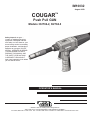
COUGAR
TM
Push Pull GUN
Models: K2704-2, K2704-3
Safety depends on you. . .
Lincoln arc welding and cutting
equipment is designed and built
with safety in mind. However, your
overall safety can be increased by
proper installation...and thoughtful
operation on your part. DO NOT
INSTALL, OPERATE OR REPAIR
THIS EQUIPMENT WITHOUT
READING THIS MANUAL AND
THE SAFETY PRECAUTIONS
CONTAINED THROUGHOUT.
And, most importantly, think before
you act and be careful.
OPERATOR’S MANUAL
• World’s Leader in Welding and Cutting Products •
• Sales and Service through Subsidiaries and Distributors Worldwide •
Cleveland, Ohio 44117-1199 U.S.A. TEL: 216.481.8100 FAX: 216 486.1751 WEB SITE: www.lincolnelectric.com

FOR ENGINE
powered equipment.
1.a. Turn the engine off before troubleshooting and maintenance
work unless the maintenance work requires it to be running.
____________________________________________________
1.b. Operate engines in open, well-ventilated
areas or vent the engine exhaust fumes
outdoors.
____________________________________________________
1.c. Do not add the fuel near an open flame weld-
ing arc or when the engine is running. Stop
the engine and allow it to cool before refuel-
ing to prevent spilled fuel from vaporizing on
contact with hot engine parts and igniting. Do
not spill fuel when filling tank. If fuel is spilled,
wipe it up and do not start engine until fumes
have been eliminated.
____________________________________________________
1.d. Keep all equipment safety guards, covers and devices in posi-
tion and in good repair.Keep hands, hair, clothing and tools
away from V-belts, gears, fans and all other moving parts
when starting, operating or repairing equipment.
____________________________________________________
1.e. In some cases it may be necessary to remove safety
guards to perform required maintenance. Remove
guards only when necessary and replace them when the
maintenance requiring their removal is complete.
Always use the greatest care when working near moving
parts.
___________________________________________________
1.f. Do not put your hands near the engine fan.
Do not attempt to override the governor or
idler by pushing on the throttle control rods
while the engine is running.
___________________________________________________
1.g. To prevent accidentally starting gasoline engines while
turning the engine or welding generator during maintenance
work, disconnect the spark plug wires, distributor cap or
magneto wire as appropriate.
i
SAFETY
i
ARC WELDING CAN BE HAZARDOUS. PROTECT YOURSELF AND OTHERS FROM POSSIBLE SERIOUS INJURY OR DEATH.
KEEP CHILDREN AWAY. PACEMAKER WEARERS SHOULD CONSULT WITH THEIR DOCTOR BEFORE OPERATING.
Read and understand the following safety highlights. For additional safety information, it is strongly recommended that you
purchase a copy of “Safety in Welding & Cutting - ANSI Standard Z49.1” from the American Welding Society, P.O. Box 351040,
Miami, Florida 33135 or CSA Standard W117.2-1974. A Free copy of “Arc Welding Safety” booklet E205 is available from the
Lincoln Electric Company, 22801 St. Clair Avenue, Cleveland, Ohio 44117-1199.
BE SURE THAT ALL INSTALLATION, OPERATION, MAINTENANCE AND REPAIR PROCEDURES ARE
PERFORMED ONLY BY QUALIFIED INDIVIDUALS.
WARNING
Mar ʻ95
ELECTRIC AND
MAGNETIC FIELDS
may be dangerous
2.a. Electric current flowing through any conductor causes
localized Electric and Magnetic Fields (EMF). Welding
current creates EMF fields around welding cables and
welding machines
2.b. EMF fields may interfere with some pacemakers, and
welders having a pacemaker should consult their physician
before welding.
2.c. Exposure to EMF fields in welding may have other health
effects which are now not known.
2.d. All welders should use the following procedures in order to
minimize exposure to EMF fields from the welding circuit:
2.d.1.
Route the electrode and work cables together - Secure
them with tape when possible.
2.d.2. Never coil the electrode lead around your body.
2.d.3. Do not place your body between the electrode and
work cables. If the electrode cable is on your right
side, the work cable should also be on your right side.
2.d.4. Connect the work cable to the workpiece as close as
possible to the area being welded.
2.d.5. Do not work next to welding power source.
1.h. To avoid scalding, do not remove the
radiator pressure cap when the engine is
hot.
CALIFORNIA PROPOSITION 65 WARNINGS
Diesel engine exhaust and some of its constituents
are known to the State of California to cause can-
cer, birth defects, and other reproductive harm.
The engine exhaust from this product contains
chemicals known to the State of California to cause
cancer, birth defects, or other reproductive harm.
The Above For Diesel Engines
The Above For Gasoline Engines

ARC RAYS can burn.
4.a. Use a shield with the proper filter and cover
plates to protect your eyes from sparks and
the rays of the arc when welding or observing
open arc welding. Headshield and filter lens
should conform to ANSI Z87. I standards.
4.b. Use suitable clothing made from durable flame-resistant
material to protect your skin and that of your helpers from
the arc rays.
4.c. Protect other nearby personnel with suitable, non-flammable
screening and/or warn them not to watch the arc nor expose
themselves to the arc rays or to hot spatter or metal.
ELECTRIC SHOCK can kill.
3.a. The electrode and work (or ground) circuits
are electrically “hot” when the welder is on.
Do not touch these “hot” parts with your bare
skin or wet clothing. Wear dry, hole-free
gloves to insulate hands.
3.b. Insulate yourself from work and ground using dry insulation.
Make certain the insulation is large enough to cover your full
area of physical contact with work and ground.
In addition to the normal safety precautions, if welding
must be performed under electrically hazardous
conditions (in damp locations or while wearing wet
clothing; on metal structures such as floors, gratings or
scaffolds; when in cramped positions such as sitting,
kneeling or lying, if there is a high risk of unavoidable or
accidental contact with the workpiece or ground) use
the following equipment:
• Semiautomatic DC Constant Voltage (Wire) Welder.
• DC Manual (Stick) Welder.
• AC Welder with Reduced Voltage Control.
3.c. In semiautomatic or automatic wire welding, the electrode,
electrode reel, welding head, nozzle or semiautomatic
welding gun are also electrically “hot”.
3.d. Always be sure the work cable makes a good electrical
connection with the metal being welded. The connection
should be as close as possible to the area being welded.
3.e. Ground the work or metal to be welded to a good electrical
(earth) ground.
3.f.
Maintain the electrode holder, work clamp, welding cable and
welding machine in good, safe operating condition. Replace
damaged insulation.
3.g. Never dip the electrode in water for cooling.
3.h. Never simultaneously touch electrically “hot” parts of
electrode holders connected to two welders because voltage
between the two can be the total of the open circuit voltage
of both welders.
3.i. When working above floor level, use a safety belt to protect
yourself from a fall should you get a shock.
3.j. Also see Items 6.c. and 8.
ii
SAFETY
ii
FUMES AND GASES
can be dangerous.
5.a. Welding may produce fumes and gases
hazardous to health. Avoid breathing these
fumes and gases. When welding, keep
your head out of the fume. Use enough
ventilation and/or exhaust at the arc to keep
fumes and gases away from the breathing zone. When
welding with electrodes which require special
ventilation such as stainless or hard facing (see
instructions on container or MSDS) or on lead or
cadmium plated steel and other metals or coatings
which produce highly toxic fumes, keep exposure as
low as possible and within applicable OSHA PEL and
ACGIH TLV limits using local exhaust or mechanical ven-
tilation. In confined spaces or in some circumstances,
outdoors, a respirator may be required. Additional pre-
cautions are also required when welding on galvanized
steel.
5. b. The operation of welding fume control equipment is affected
by various factors including proper use and positioning of the
equipment, maintenance of the equipment and the specific
welding procedure and application involved. Worker expo-
sure level should be checked upon installation and periodi-
cally thereafter to be certain it is within applicable OSHA PEL
and ACGIH TLV limits.
5.c.
Do not weld in locations near chlorinated hydrocarbon
vapors
coming from degreasing, cleaning or spraying operations.
The heat and rays of the arc can react with solvent vapors
to
form phosgene, a highly toxic gas, and other irritating prod-
ucts.
5.d. Shielding gases used for arc welding can displace air and
cause injury or death. Always use enough ventilation,
especially in confined areas, to insure breathing air is safe.
5.e. Read and understand the manufacturerʼs instructions for this
equipment and the consumables to be used, including the
material safety data sheet (MSDS) and follow your
employerʼs safety practices. MSDS forms are available from
your welding distributor or from the manufacturer.
5.f. Also see item 1.b.
Jan ʻ09

FOR ELECTRICALLY
powered equipment.
8.a. Turn off input power using the disconnect
switch at the fuse box before working on
the equipment.
8.b. Install equipment in accordance with the U.S. National
Electrical Code, all local codes and the manufacturerʼs
recommendations.
8.c. Ground the equipment in accordance with the U.S. National
Electrical Code and the manufacturerʼs recommendations.
CYLINDER may explode
if damaged.
7.a. Use only compressed gas cylinders
containing the correct shielding gas for the
process used and properly operating
regulators designed for the gas and
pressure used. All hoses, fittings, etc. should be suitable for
the application and maintained in good condition.
7.b. Always keep cylinders in an upright position securely
chained to an undercarriage or fixed support.
7.c. Cylinders should be located:
• Away from areas where they may be struck or subjected to
physical damage.
• A safe distance from arc welding or cutting operations and
any other source of heat, sparks, or flame.
7.d. Never allow the electrode, electrode holder or any other
electrically “hot” parts to touch a cylinder.
7.e. Keep your head and face away from the cylinder valve outlet
when opening the cylinder valve.
7.f. Valve protection caps should always be in place and hand
tight except when the cylinder is in use or connected for
use.
7.g. Read and follow the instructions on compressed gas
cylinders, associated equipment, and CGA publication P-l,
“Precautions for Safe Handling of Compressed Gases in
Cylinders,” available from the Compressed Gas Association
1235 Jefferson Davis Highway, Arlington, VA 22202.
WELDING and CUTTING
SPARKS can
cause fire or explosion.
6.a.
Remove fire hazards from the welding area.
If this is not possible, cover them to prevent
the welding sparks from starting a fire.
Remember that welding sparks and hot
materials from welding can easily go through small cracks
and openings to adjacent areas. Avoid welding near
hydraulic lines. Have a fire extinguisher readily available.
6.b. Where compressed gases are to be used at the job site,
special precautions should be used to prevent hazardous
situations. Refer to “Safety in Welding and Cutting” (ANSI
Standard Z49.1) and the operating information for the
equipment being used.
6.c. When not welding, make certain no part of the electrode
circuit is touching the work or ground. Accidental contact can
cause overheating and create a fire hazard.
6.d. Do not heat, cut or weld tanks, drums or containers until the
proper steps have been taken to insure that such procedures
will not cause flammable or toxic vapors from substances
inside. They can cause an explosion even
though
they have
been “cleaned”. For information, purchase “Recommended
Safe Practices for the
Preparation
for Welding and Cutting of
Containers and Piping That Have Held Hazardous
Substances”, AWS F4.1 from the American Welding Society
(see address above).
6.e. Vent hollow castings or containers before heating, cutting or
welding. They may explode.
6.f.
Sparks and spatter are thrown from the welding arc. Wear oil
free protective garments such as leather gloves, heavy shirt,
cuffless trousers, high shoes and a cap over your hair. Wear
ear plugs when welding out of position or in confined places.
Always wear safety glasses with side shields when in a
welding area.
6.g. Connect the work cable to the work as close to the welding
area as practical. Work cables connected to the building
framework or other locations away from the welding area
increase the possibility of the welding current passing
through lifting chains, crane cables or other alternate circuits.
This can create fire hazards or overheat lifting chains or
cables until they fail.
6.h. Also see item 1.c.
6.I. Read and follow NFPA 51B “ Standard for Fire Prevention
During Welding, Cutting and Other Hot Work”, available from
NFPA, 1 Batterymarch Park, PO box 9101, Quincy, Ma
022690-9101.
6.j. Do not use a welding power source for pipe thawing.
iii
SAFETY
iii
Jan ʻ09
Refer to http://www.lincolnelectric.com/safety for additional safety information.

PRÉCAUTIONS DE SÛRETÉ
Pour votre propre protection lire et observer toutes les instructions
et les précautions de sûreté specifiques qui parraissent dans ce
manuel aussi bien que les précautions de sûreté générales suiv-
antes:
Sûreté Pour Soudage A LʼArc
1. Protegez-vous contre la secousse électrique:
a. Les circuits à lʼélectrode et à la piéce sont sous tension
quand la machine à souder est en marche. Eviter toujours
tout contact entre les parties sous tension et la peau nue
ou les vétements mouillés. Porter des gants secs et sans
trous pour isoler les mains.
b. Faire trés attention de bien sʼisoler de la masse quand on
soude dans des endroits humides, ou sur un plancher met-
allique ou des grilles metalliques, principalement dans
les positions assis ou couché pour lesquelles une grande
partie du corps peut être en contact avec la masse.
c. Maintenir le porte-électrode, la pince de masse, le câble de
soudage et la machine à souder en bon et sûr état defonc-
tionnement.
d.Ne jamais plonger le porte-électrode dans lʼeau pour le
refroidir.
e. Ne jamais toucher simultanément les parties sous tension
des porte-électrodes connectés à deux machines à souder
parce que la tension entre les deux pinces peut être le total
de la tension à vide des deux machines.
f. Si on utilise la machine à souder comme une source de
courant pour soudage semi-automatique, ces precautions
pour le porte-électrode sʼapplicuent aussi au pistolet de
soudage.
2. Dans le cas de travail au dessus du niveau du sol, se protéger
contre les chutes dans le cas ou on recoit un choc. Ne jamais
enrouler le câble-électrode autour de nʼimporte quelle partie du
corps.
3. Un coup dʼarc peut être plus sévère quʼun coup de soliel, donc:
a. Utiliser un bon masque avec un verre filtrant approprié ainsi
quʼun verre blanc afin de se protéger les yeux du rayon-
nement de lʼarc et des projections quand on soude ou
quand on regarde lʼarc.
b. Porter des vêtements convenables afin de protéger la peau
de soudeur et des aides contre le rayonnement de lʻarc.
c. Protéger lʼautre personnel travaillant à proximité au
soudage à lʼaide dʼécrans appropriés et non-inflammables.
4. Des gouttes de laitier en fusion sont émises de lʼarc de
soudage. Se protéger avec des vêtements de protection libres
de lʼhuile, tels que les gants en cuir, chemise épaisse, pan-
talons sans revers, et chaussures montantes.
5. Toujours porter des lunettes de sécurité dans la zone de
soudage. Utiliser des lunettes avec écrans lateraux dans les
zones où lʼon pique le laitier.
6. Eloigner les matériaux inflammables ou les recouvrir afin de
prévenir tout risque dʼincendie dû aux étincelles.
7. Quand on ne soude pas, poser la pince à une endroit isolé de
la masse. Un court-circuit accidental peut provoquer un
échauffement et un risque dʼincendie.
8. Sʼassurer que la masse est connectée le plus prés possible de
la zone de travail quʼil est pratique de le faire. Si on place la
masse sur la charpente de la construction ou dʼautres endroits
éloignés de la zone de travail, on augmente le risque de voir
passer le courant de soudage par les chaines de levage,
câbles de grue, ou autres circuits. Cela peut provoquer des
risques dʼincendie ou dʼechauffement des chaines et des
câbles jusquʼà ce quʼils se rompent.
9. Assurer une ventilation suffisante dans la zone de soudage.
Ceci est particuliérement important pour le soudage de tôles
galvanisées plombées, ou cadmiées ou tout autre métal qui
produit des fumeés toxiques.
10. Ne pas souder en présence de vapeurs de chlore provenant
dʼopérations de dégraissage, nettoyage ou pistolage. La
chaleur ou les rayons de lʼarc peuvent réagir avec les vapeurs
du solvant pour produire du phosgéne (gas fortement toxique)
ou autres produits irritants.
11. Pour obtenir de plus amples renseignements sur la sûreté, voir
le code “Code for safety in welding and cutting” CSA Standard
W 117.2-1974.
PRÉCAUTIONS DE SÛRETÉ POUR
LES MACHINES À SOUDER À
TRANSFORMATEUR ET À
REDRESSEUR
1. Relier à la terre le chassis du poste conformement au code de
lʼélectricité et aux recommendations du fabricant. Le dispositif
de montage ou la piece à souder doit être branché à une
bonne mise à la terre.
2. Autant que possible, Iʼinstallation et lʼentretien du poste seront
effectués par un électricien qualifié.
3. Avant de faires des travaux à lʼinterieur de poste, la debranch-
er à lʼinterrupteur à la boite de fusibles.
4. Garder tous les couvercles et dispositifs de sûreté à leur place.
Mar. ʻ93
iv
SAFETY
iv

v
v
Thank You
for selecting one of our QUALITY products. We want you to take
pride in operating this product ••• as much pride as we have in
bringing this product to you!
Read this Operators Manual completely before attempting to use this equipment. Save this manual and keep it
handy for quick reference. Pay particular attention to the safety instructions we have provided for your protection.
The level of seriousness to be applied to each is explained below:
WARNING
This statement appears where the information must be followed exactly to avoid serious personal injury or loss of life.
This statement appears where the information must be followed to avoid minor personal injury or damage to this equipment.
CAUTION
Please Examine Carton and Equipment For Damage Immediately
When this equipment is shipped, title passes to the purchaser upon receipt by the carrier. Consequently, Claims
for material damaged in shipment must be made by the purchaser against the transportation company at the time
the shipment is received.
Please record your equipment identification information below for future reference. This information can be found
on your machine nameplate.
Product _________________________________________________________________________________
Model Number ___________________________________________________________________________
Code Number or Date Code (if available)______________________________________________________
Serial Number (if available)__________________________________________________________________
Date Purchased___________________________________________________________________________
Where Purchased_________________________________________________________________________
Whenever you request replacement parts or information on this equipment, always supply the information you
have recorded above.
CUSTOMER ASSISTANCE POLICY
The business of our company is manufacturing and selling high quality welding equipment. Our challenge is to
meet the needs of our customers and to exceed their expectations. On occasion, purchasers may ask us for
advice or information about their use of our products. We respond to our customers based on the best informa-
tion in our possession at that time. We are not in a position to warrant or guarantee such advice, and assume no
liability, with respect to such information or advice. We expressly disclaim any warranty of any kind, including any
warranty of fitness for any customerʼs particular purpose, with respect to such information or advice. As a matter
of practical consideration, we also cannot assume any responsibility for updating or correcting any such informa-
tion or advice once it has been given, nor does the provision of information or advice create, expand or alter any
warranty with respect to the sale of our products.
We are a responsive manufacturer, but the selection and use of specific products sold by us is solely within the
control of, and remains the sole responsibility of the customer. Many variables beyond our control affect the results
obtained in applying these types of fabrication methods and service requirements.
Subject to Change – This information is accurate to the best of our knowledge at the time of printing.

1
TABLE OF CONTENTS
SAFETY PRECAUTIONS ...........................................................................................................................................i-v
TABLE OF CONTENTS................................................................................................................................................1
GENERAL INFORMATION ...........................................................................................................................................2
PRODUCT DESCRIPTION...........................................................................................................................................2
SPECIFICATIONS ........................................................................................................................................................2
RECOMMENDED PROCESSES AND EQUIPMENT ..................................................................................................2
INSTALLATION.........................................................................................................................................................3, 4
UNPACKING THE PUSH-PULL GUN ..........................................................................................................................3
PUSH-PULL GUN FAMILARIZATION DIAGRAM ........................................................................................................4
OPERATING INSTRUCTIONS..................................................................................................................................5-7
SAFETY PRECAUTIONS .............................................................................................................................................5
SET-UP PROCEDURE .................................................................................................................................................5
SELECTING ELECTRODE WIRE ................................................................................................................................5
LOADING ELECTRODE WIRE ....................................................................................................................................5
INSTALLING BARREL LINER ......................................................................................................................................5
DRIVE ROLL GROOVE SELECTION ..........................................................................................................................6
MAKING A WELD .........................................................................................................................................................7
PROCEDURE SETTINGS ............................................................................................................................................7
SETTING GAS FLOW RATE........................................................................................................................................7
ACCESSORIES ............................................................................................................................................................8
MAINTENANCE............................................................................................................................................................8
TROUBLESHOOTING GUIDE ...............................................................................................................................9, 10
REPLACEMENT PARTS LIST DIAGRAM .............................................................................................................11,12

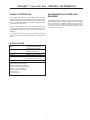
PRODUCT DESCRIPTION
The Cougar™ push-pull gun is a lightweight, handheld combined
semiautomatic wire feeder and welding gun, designed primarily for
aluminum welding using argon shielding gas. The cable included
with the push-pull gun allows welding up to 25 (7.62m) or 50 feet
(15.2m) from the power source.
The gun is intended for use with Power Wave C300, Power Feed
10M, Power Feed 25M and Power Mig 350MP Power Sources. For
other applications, contact your local Lincoln Electric sales office or
distributor.
The push-pull gun is ideal for aluminum fabrication in industrial
shops, automobile body shops, marinas and for the advanced hob-
byist.
RECOMMENDED PROCESSES AND
EQUIPMENT
The push-pull gun can be used to weld aluminum and aluminum
alloys using Gas Metal Arc Welding or GMAW (also known as MIG)
process, which requires a supply of shielding gas. Argon is normal-
ly used due to its smooth, stable arc, good metal transfer, and low
cost. Positive polarity gives good penetration and affords a base
metal cathode cleaning effect.
COUGAR™ Push Pull Gun - GENERAL INFORMATION
2
Model Cougar™ Push-Pull Gun with
Remote Wire Speed Control
Wire Capacity .035"-1/16” (0.8mm-1.6mm)
Aluminum and cored wire
Wire Speed 800 IPM MAX.
Duty Cycle 300 amps @ 60% Argon Gas
Shipping Weight 25 Ft. (7.6m) - 17 Lbs. (7.7Kg.)
50 Ft. (15.2m) - 31 Lbs. (14Kg)
Supplied with:
KP2744-364A, 3/64” Contact Tip (Installed)
KP2744-035A, .035 Contact Tip
KP2746-1, Gas Diffuser (Installed)
KP2742-1-62R, Gas Nozzle (Installed)
KP2773-2, Insulator (Installed)
KP2876-1, Drive Roll (.035-3/64)
Service Wrench
Instruction Manual
SPECIFICATIONS

Unpacking the Push-Pull Gun
Safety Precautions
– Read "Safety Precautions" in the Operating Manual before
proceeding. Only personnel that have read and understood
the Operating Manual should install and operate this equipment.
– Power source must be turned "OFF" and power leads disconnected
when installing this unit.
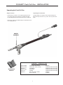
Unpacking the Push-Pull Gun
Carefully unpack your Cougar™ Push-Pull Gun and attach the
Barrel Assembly, and make sure you have all of the parts shown
below.
COUGAR™ Push Pull Gun - INSTALLATION
BARREL
ASSEMBLY
OPERATOR’S
MANUAL
3
COUGAR™ - PUSH-PULL GUN
KP2744-035A Contact Tip .035 (0.9mm) Included
KP2744-364A Contact Tip . 3/64” (1.2mm) Installed on Barrel Assembly
KP2746-1 Gas Diffuser Installed on Barrel Assembly
KP742-1-62R Gas Nozzle Installed on Barrel Assembly
KP2773-2 Insulator Installed on Barrel Assembly
KP2876-1 Drive Roll (.035 / 3/64th) Installed
Service Wrench Included

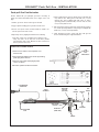
Push-pull Gun Familiarization
Become familiar with your push-pull gun before connecting to
welder. For features described below, refer to Figure on the next
page.
1. Handle, gun can be used in either right or left hand.
2. Trigger operates welding power, gas flow, and wire feed.
3. Remote wire speed control, located behind the handle, con-
trols the speed of the drive motor.
4. Open body cover by flipping lid and observe the following:
a.Wire drive release lever up position moves pressure roller
away from drive roll to stop wire feed. Down position
movespressure roller to wire. Operate wire drive release lever
and see pressure roller move.
b.Drive roll with two wire grooves. Narrow groove feeds .035 (0.9
mm) diameter wire. Wide groove feeds 3/64 inch (1.2 mm)
diameter wire. Gun is shipped with wide groove or 3/64 in
operating position (toward handle). Reverse roller for .035
inch (0.9 mm) diameter wire.
5. Gas nozzle directs gas flow around arc. Unthread gas nozzle to
see contact tip and gas diffuser. Push-pull gun is shipped with
3/64th inch (1.2 mm) contact tip installed.
6. Cable assembly for power, control, and gas. Hold gun and
become familiar with gun's weight and balance.
COUGAR™ Push Pull Gun - INSTALLATION
4
CONTACT
TIP
PRESSURE
ROLLER
(FAR SIDE)
GAS
NOZZLE
TRIGGER
WIRE SPEED
CONTROL
HANDLE
LINCOLN POWER
PLUG
GAS
DIFFUSOR
CABLE
ASSEMBLY
DRIVE ROLL
(NEAR SIDE)
GUN
BARREL
7 PIN AMPHENOL
CONNECTOR
7-PIN
PUSH-PULL
GUN
RECEPTACLE
CONNECTING TO POWER SOURCE:
1. Power source must be “off” and power cord
disconnected.
2. Connect Push-Pull Gun to wire feeder by inserting
power plug to the machine
3. Connect 7-Pin control cable plug to power
source receptacle.
4. Reconnect power and turn on machine.

Safety Precautions
WARNING
• Do not touch electrically live
parts or electrode with skin
or wet clothing
• Insulate yourself from work
and ground.
• Always wear dry insulating
gloves.
ELECTRIC SHOCK
can kill.
• Keep your head out of fumes.
• Use ventilation or exhaust to
remove fumes from breathing
zone.
FUMES AND GASES can be
dangerous.
• Keep flammable material
away.
• Do not weld on containers
that have held combustibles.
WELDING SPARKS can
cause fire or explosion.
• Wear eye, ear and body
protection..
ARC RAYS can burn.
WARNING: Electric shock can kill. Fumes and gases can be
dangerous to your health. Arc rays can injure eyes and burn
skin. See additional warning information under "Arc Welding
Safely Precautions" on inside of front cover of operating manual.
When inching, (the electrode and drive mechanism are always
electrically energized and remain energized several seconds
after the gun trigger is released.
Setup Procedure
Selecting Electrode Wire
Several alloy types of filler metals are available, and the best
choice depends on the type of base metals and the desired
characteristics of the weldment, such as ductility and strength,
corrosion resistance, sustained service temperature, and anodic
treatment color matching. In addition, several wire sizes are
available, and the choice here will depend upon several fac-
tors, including base metal thickness and the arc transfer process
used. Consult your local dealer or appropriate AWS publication
for help in selecting an appropriate alloy type and wire size. Also
refer to, "Procedure Settings" later in this chapter, for wire sizes
used with typical base metal thicknesses and procedure set-
tings.
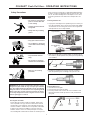
Installing Conduit Liner:
1. Laying torch out straight remove positioning nut, then insert your
liner, tapered end first, all the way into torch until it stops. NOTE:
You should see the liner through the holes in the inlet guide this
will help make sure liner is fully installed.
2. While torch is still laying out straight adjust your O-Ring and col-
let so that they will fit up inside of the power-pin when positioning
nut is installed.
3. Reinstall the positioning nut securely, then trim rest of liner
flush with positioning nut, accordingly to fit up to drive rolls.
Installing Barrel Liner
1. Unscrew barrel inlet guide
2. Unscrew barrel liner from inlet guide
3. Reverse procedure with new liner. Be sure to install liner with
tapered end toward contact tip, and liner is fully threaded into
inlet guide.
Positioning Nut Collet
O-Ring
COUGAR™ Push Pull Gun - OPERATING INSTRUCTIONS
5
Inlet Guide with Liner
Inspection Hole
Liner Positioning
Nut
Torch
Barrel
Neck
Liner
Barrel
Inlet
Guide

COUGAR™ Push Pull Gun - OPERATING INSTRUCTIONS
LID
RELEASE LEVER
6
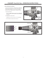
Drive Roll Groove Selection
The drive roll has two grooves. A wider groove for feeding 3/64”
(.047) wire and a narrow groove for feeding .035” (0.9mm) wire
to accommodate changes in the wire size used. Changing
between the grooves simply requires reversing the drive roll.
A. Drive Roll Orientation
1. Drive roll is scribed with wire groove size. For appropriate
groove orientation, ensure desired size callout is facing up
and visible.
B. Changing Drive Roll Orientation
1. Flip lid open, then move release lever to the up position.
2. Unscrew thumb screw and remove drive roll
THUMB SCREW
RELEASE LEVER
PRESSURE
ADJUSTMENT
KNOB
DRIVE ROLL
3/64”
.035”

7
COUGAR™Push Pull Gun - OPERATING INSTRUCTIONS
Making A Weld
1 Check that the push-pull gun power, control, and gas connec-
tions are correct for the power source being used. Check that
the gas supply is turned on. Check wire push-pull for an ade-
quate supply of wire.
2. See "Procedure Settings", below for wire feed speed and
voltage settings. Set these controls depending on the weld-
ing wire and base metal thickness being used.
3. Connect work clamp to metal being welded. Work clamp must
make good electrical contact to the workpiece. The workpiece
must also be grounded as stated in "Arc Welding Safety
Precautions".
4. Connect power to welder and turn "ON".
5. Prepare to purge gas line by first releasing wire drive. Push
wire drive release lever to the UP position, to avoid feeding
wire.
WARNING: Gun body and contact tip become
electrically energized when gun trigger is pressed
and remain so for several seconds
after trigger is released.
6. Press and hold gun trigger for about 5 seconds to purge gas
line. If adjustable regulator or metering valve is installed, adjust
gas flow per, "Setting Gas Flow Rate".
7. Re-engage wire drive by pushing release lever to down posi-
tion to feed wire.
8. Momentarily squeeze trigger and verify that wire feeds proper-
ly. Trim wire to approximately 1/4" (6 mm) from end of contact
tip.
WARNING: When using an open arc process, it is
necesary to use correct eye, ear, head,
and body protection.
9. Position gun over joint at 10° pushing angle. End of wire may
be lightly touching the work.
10. Lower welding helmet, close gun trigger, and begin welding.
Hold the gun so that the contact tip to work distance is about
1/2 inch (13 mm).
11. To stop welding, release the gun trigger and then pull the gun
away from the work after the arc goes out.
12. When no more welding is to be done, close valve on gas cylin-
der, momentarily operate trigger to release gas pressure in line
and turn off power source.
13. Note that clogged tips can often be salvaged by peeling away
melted wire.
Procedure Settings
The following procedure settings for 4043 aluminum wire and argon
gas can be used as starting points for developing specific welding
procedures:
Wire Metal Wire Amps
Size Thickness Speed DC
in. (mm) ga. in. (mm) Arc Volts ipm (mpm) (+}
.030 (0.8) 22 .030 (0.8) 13-14
(1)
200 (5.1) 40
20 .036 (1.0) 13-14
(1)
240 (6.1) 40
18 .048 (1.2) 14-15
(1)
290 (7.4) 50
16 .060 (1.6) 15-16
(1)
340 (8.6) 60
14 .075 (2.0) 16-17
(1)
370 (9.4) 70
12 .105 (2.5) 16-18
(1)
430 (10.9) 90
10 .135 (3.5) 24-26 460 (11.7) 110
3/16 (5.0) 24-26 500 (12.7) 150
1/4 (6.0) 28-29 560 (14.2) 180
3/8 (10.0) 28-30 600 (15.2) 200
.035 (0.9) 22 .030 (0.8) 13-14
(1)
150 (3.8) 40
20 .036 (1.0) 13-14
(1)
175 (4.4) 40
18 .048 (1.2) 13-14
(1)
215 (5.5) 50
16 .060 (1.6) 14-16
(1)
250 (6.4) 60
14 .075 (2.0) 14-16
(1)
270 (6.9) 70
12 .105 (2.5) 16-18
(1)
320 (8.1) 90
10 .135 (3.5) 24-26 410 (10.4) 110
3/16 (5.0) 24-26 450 (11.4) 150
1/4 (6.0) 26-28 530 (13.5) 180
3/8 (10.0) 26-29 560 (14.2) 200
1/2 (12.0) 26-30 600 (15.2) 220
3/64(1.2) 10 .135 (3.5) 20-21
(1)
180 (4.6) 110
3/16 (5.0) 20-21
(1)
220 (5.6) 150
1/4 (6.0) 27-28 250 (6.4) 180
3/8 (10.0) 25-30 260 (6.6) 200
1/2 (12.0) 25-31 270 (6.9) 220
3/4 (20.0) 25-31 290 (7.4) 250
(1)
Short arc transfer.
Setting Gas Flow Rate
Gas handling systems having adjustable flow valves should be
set for the following argon flow rates, depending on base metal
thickness and welding position.
ARGON SHIELDING GAS FLOW RATES
Material Thickness Flow Rates
In Inches and (mm) Welding Position In cf/hr (l/mln)
1/16 (1.6 mm) Flat 30
(11.8)
3/32 to 3/16 Flat, Vertical, 35
(2.4 to 4.8 mm) Horizontal, Overhead (14)
1/4 to 3/8 Flat, Vertical, 35 (14)
(6.3 to 9.5 mm) Flat Vertical, 35 (16.5)
Horizontal, Overhead 40 (18.9)
3/4 (19 mm) Flat, Vertical 35 (16.5)
Horizontal, Overhead 40 (18.9)

COUGAR™ Push Pull Gun ACCESSORIES/MAINTENANCE
The following accessories are available for the Cougar™ push-pull
gun.
.035-3/64" Aluminum Drive Roll Kit
Features two grooves for feeding aluminum wire. The smaller
groove feeds .035 wire. The larger groove feeds 3/64th wire.
Order KP2876-1
1/16" Aluminum Drive Roll Kit
Features two grooves, each capable of feeding 1/16"
Aluminum wire
Order KP2876-2
Barrel Liner (45°, 60° Barrels)
Liner for feeding up to1/16” wire.
Order KP2879-1
Barrel Liner (180° Straight Barrel)
Liner for feeding up to1/16” wire.
Order KP2879-2
Gun Barrel
60 degree air-cooled gun barrel Order KP2877-60
45 degree air-cooled gun barrel Order KP2877-45
180 degree air-cooled gun barrel Order KP2877-180
Wire Conduits
25 foot .035"-1/16" Wire Diameter Order KP2881-25
50 foot .035"-1/16" Wire Diameter Order KP2881-50
Gas Diffuser
Diffuser designed to accept thread on gas nozzles
Order KP2746-1
Gun Tube Insulator
For insulation of gas nozzle
Order KP2773-2
Gas Nozzle
.50 Thread on Nozzle (Tip Recessed) Order KP2742-1-50R
.62 Thread on Nozzle (Tip Recessed) Order KP2742-1-62R
Contact Tips
.035 Order KP2744-035A
3/64" Order KP2744-364A
3/64" (5356)
1.
Order KP2744-364A5356
1/16” Order KP2744-116A
8
ACCESSORIES (consult Lincoln Sales Bulletin E12.16)
1.
For use on lower amperage applications with 5356 wire. Features a smaller
tip inner diameter to reduce arc flaring.
MAINTENANCE
Safety Precautions
WARNING
• Do not operate with covers
removed.
• Disconnect input power from
welder before installing gun.
• Do not touch electrically hot
part.
• Only qualified persons
should install, use or service
this machine.
ELECTRIC SHOCK
can kill.
When finished welding, be sure to turn power source off and
close valve on gas cylinder.
WARNING
• Working with flying or falling objects can cause serious eye
injuries.
• Protective eyeware such as safety specticals with side
shields or goggles must be worn at all times.
FLYING FRAGMENTS
can cause eye injury.
Routine Maintenance
Periodically blow out or vacum any metal wire shavings from Drive
Roll area.
Inspect and replace any worn wire on inlet guide or barrel liner.
NOTE: Oil and spray cleaners can contaminate electrode wire and
cause bad welds. They could also make wire drive rollers slip. Be
careful when using any of these liquids on push-pull gun.
Carefully clean gun with a cleaner that is safe for plastic. Apply
cleaner to rag and wipe gun. Do NOT spray cleaner on gun. Keep
cable clean. Oil, grease gasoline, paint, and solvents degrade cable
insulation.
Routine maintenance for consumable spare parts will depend on Duty Cycle and
particular application.

COUGAR™ Push Pull Gun
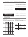
Troubleshooting Guide
PROBLEM SYMPTOMS REMEDY
No arc, wire feed, or gas flow. 1. Cable connections loose. 1. Check all power connections.
2. Trigger switch loose or defective. 2. Fix switch or replace.
3. Welder not turned on. 3. Turn on welder power.
4. Welder not plugged in. 4. Plug in.
5. Cable or adapter cable damaged. 5. Inspect and replace
No arc, weak arc. 1. Poor ground connection to work. 1. Check ground connection.
2. Power cable connection loose. 2. Check connections; if defective,
replace cable or connectors.
3. Voltage set too low. 3. Adjust to proper voltage
4. Tip too large for wire size. 4. Change tip size.
5. Wire feed speed too slow. 5. Increase wire feed speed.
No wire feed. 1. Feeding small diameter wire with large 1. Change position of wire drive roller.
groove on drive roller.
2. Wire drive release open. 2. Close wire drive release.
3. Wire welded to tip. 3. Peel wire off tip or use new tip.
4. Wire push-pull empty in machine. 4. Insert new push-pull.
5. Tip too small for wire. 5. Insert correct tip.
6. Kink or bend in wire. 6. Pull wire through tip or start new
wire end.
7. Control cable loose. 7. Check all connections.
8. Drive roller worn. 8. Replace.
9. Pressure roller stuck. 9. Replace or lubricate.
10. Roller spring loose or broken. 10. Replace.
Wire feed too fast or too slow. 1. Wrong wire speed set for work. 1. Adjust wire feed speed.
Low or no gas flow. Oxidation of work. 1. Gas flow not set right. 1. Set proper flow rate.
2. Cylinder out of gas. 2. Get new cylinder of gas.
3. Cylinder valve closed. 3. Open cylinder valve.
4. Leak in gas line. 4. Inspect and replace.
5. Leak in gun. 5. Check for missing gun tubes and/or
missing gun body cover.
6.Gas diffuser clogged 6. Blow out gas diffuser openings.
Oxidized work, arc unstable. 1. Wrong welding polarity. 1. Check polarity.
9

COUGAR™ Push Pull Gun
Troubleshooting Guide
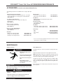
TESTING THE TORCH
Motor Check. Remove the torch connector from the cabinet.
Using the torch Control Cable Connector, check the resistance across pins “A”
and “B” (motor leads). The resistance across the motor should be between 5-10
ohms. If an open circuit or short exist, check the motor leads and motor
independently.
Testing the Potentiometer. Using the torch Control Cable Connector, check the resistance across pin “D”
(wiper) and pin “C”. The resistance should vary from 5K - 0 ohms.
Check the resistance across pin “D” (wiper) and pin “G”. The resistance should
vary from 5K - 0 ohms.
Testing the Trigger Switch. Using the torch Control Cable Connector, check for continuity across pins “E”
and “F” when the trigger is pressed.
10

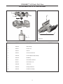
COUGAR™ Push Pull Gun
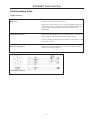
REPLACEMENT PARTS LIST AND DIAGRAM
11
1
9
11
2
3
4
5
10
6
7
8
ITEM PART
NO. NO. DESCRIPTION
1 KP2877-180 180 Degree Air-Cooled Gun Barrel
2 S26374-31 Motor Assembly
3 S26374-6 Wire Drive Cover
4 S26374-14 Potentiometer Assembly
5 S26374-23 Trigger Assembly
6 S26374-24 Handle, Front
7 S26374-25 Handle, Back
8 S26374-33 Strain Relief Clamp Kit
9 S26374-95 Barrel Nut
10 S26374-104 Barrel Insulation Hose
11 S26374-46 Barrel Inlet Guide
N/S S26374-44 O-Ring Kit A/C Barrel
N/S S26374-28 25' Cable Assembly - Cougar
ITEM PART
NO. NO. DESCRIPTION
N/S S26374-34 50' Cable Assembly - Cougar
N/S S26374-35 Cable Cover 25
N/S S26374-36 Cable Cover 50'
N/S S26374-37 Power Cable Assembly 25'
N/S S26374-38 Power Cable Assembly 50'
N/S S26374-39 Wire Conduit Assembly 25'
N/S S26374-40 Wire Conduit Assembly 50'
N/S S26374-41 Control Wire Assembly 25'
N/S S26374-42 Control Wire Assembly 50'
N/S S26374-60 Gas Hose Assembly 25'
N/S S26374-61 Gas Hose Assembly 50'
N/S S26374-32 Rear End Feeder Connection Kit
N/S = Not Shown

S26374-14
COUGAR™ LX Push Pull Gun
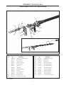
REPLACEMENT PARTS LIST AND DIAGRAM
ITEM NO. PART NO. DESCRIPTION COMMENTS
1 S26374-31 Motor Assembly
2 S26374-7 Pressure Lever
3 S26374-8 Pivot Arm
4 S26374-9 Set Screw, Pressure Roll
5 S26374-10 Pressure Adjustment Knob Assembly
6 S26374-12 Ball Bearing
7 KP2876-1 Drive Roll Kit AL .035-3/64"
7 KP2876-2 Drive Roll Kit AL 1/16"
8 S26374-63 Thumb Screw
9 S26374-15 Housing, Potentiometer
10 S26374-14 Potentiometer Assembly
12
1
2
3
4
7
8
5
6
9
10

13
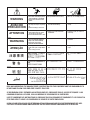
WARNING
AVISO DE
PRECAUCION
ATTENTION
WARNUNG
ATENÇÃO
Spanish
French
German
Portuguese
Japanese
Chinese
Korean
Arabic
READ AND UNDERSTAND THE MANUFACTURER’S INSTRUCTION FOR THIS EQUIPMENT AND THE CONSUMABLES TO
BE USED AND FOLLOW YOUR EMPLOYER’S SAFETY PRACTICES.
SE RECOMIENDA LEER Y ENTENDER LAS INSTRUCCIONES DEL FABRICANTE PARA EL USO DE ESTE EQUIPO Y LOS
CONSUMIBLES QUE VA A UTILIZAR, SIGA LAS MEDIDAS DE SEGURIDAD DE SU SUPERVISOR.
LISEZ ET COMPRENEZ LES INSTRUCTIONS DU FABRICANT EN CE QUI REGARDE CET EQUIPMENT ET LES PRODUITS A
ETRE EMPLOYES ET SUIVEZ LES PROCEDURES DE SECURITE DE VOTRE EMPLOYEUR.
LESEN SIE UND BEFOLGEN SIE DIE BETRIEBSANLEITUNG DER ANLAGE UND DEN ELEKTRODENEINSATZ DES HER-
STELLERS. DIE UNFALLVERHÜTUNGSVORSCHRIFTEN DES ARBEITGEBERS SIND EBENFALLS ZU BEACHTEN.
● Do not touch electrically live parts or
electrode with skin or wet clothing.
● Insulate yourself from work and
ground.
● No toque las partes o los electrodos
bajo carga con la piel o ropa moja-
da.
● Aislese del trabajo y de la tierra.
● Ne laissez ni la peau ni des vête-
ments mouillés entrer en contact
avec des pièces sous tension.
● Isolez-vous du travail et de la terre.
● Berühren Sie keine stromführenden
Teile oder Elektroden mit Ihrem
Körper oder feuchter Kleidung!
● Isolieren Sie sich von den
Elektroden und dem Erdboden!
● Não toque partes elétricas e elec-
trodos com a pele ou roupa molha-
da.
● Isole-se da peça e terra.
● Keep flammable materials away.
● Mantenga el material combustible
fuera del área de trabajo.
● Gardez à l’écart de tout matériel
inflammable.
● Entfernen Sie brennbarres Material!
● Mantenha inflamáveis bem guarda-
dos.
● Wear eye, ear and body protection.
● Protéjase los ojos, los oídos y el
cuerpo.
● Protégez vos yeux, vos oreilles et
votre corps.
● Tragen Sie Augen-, Ohren- und Kör-
perschutz!
● Use proteção para a vista, ouvido e
corpo.

14
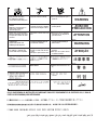
WARNING
AVISO DE
PRECAUCION
ATTENTION
WARNUNG
ATENÇÃO
Spanish
French
German
Portuguese
Japanese
Chinese
Korean
Arabic
LEIA E COMPREENDA AS INSTRUÇÕES DO FABRICANTE PARA ESTE EQUIPAMENTO E AS PARTES DE USO, E SIGA AS
PRÁTICAS DE SEGURANÇA DO EMPREGADOR.
● Keep your head out of fumes.
● Use ventilation or exhaust to
remove fumes from breathing zone.
● Los humos fuera de la zona de res-
piración.
● Mantenga la cabeza fuera de los
humos. Utilice ventilación o
aspiración para gases.
● Gardez la tête à l’écart des fumées.
● Utilisez un ventilateur ou un aspira-
teur pour ôter les fumées des zones
de travail.
● Vermeiden Sie das Einatmen von
Schweibrauch!
● Sorgen Sie für gute Be- und
Entlüftung des Arbeitsplatzes!
● Mantenha seu rosto da fumaça.
● Use ventilação e exhaustão para
remover fumo da zona respiratória.
● Turn power off before servicing.
● Desconectar el cable de ali-
mentación de poder de la máquina
antes de iniciar cualquier servicio.
● Débranchez le courant avant l’entre-
tien.
● Strom vor Wartungsarbeiten
abschalten! (Netzstrom völlig öff-
nen; Maschine anhalten!)
● Não opere com as tampas removidas.
● Desligue a corrente antes de fazer
serviço.
● Não toque as partes elétricas nuas.
● Do not operate with panel open or
guards off.
● No operar con panel abierto o
guardas quitadas.
● N’opérez pas avec les panneaux
ouverts ou avec les dispositifs de
protection enlevés.
● Anlage nie ohne Schutzgehäuse
oder Innenschutzverkleidung in
Betrieb setzen!
● Mantenha-se afastado das partes
moventes.
● Não opere com os paineis abertos
ou guardas removidas.
La page est en cours de chargement...
La page est en cours de chargement...
-
 1
1
-
 2
2
-
 3
3
-
 4
4
-
 5
5
-
 6
6
-
 7
7
-
 8
8
-
 9
9
-
 10
10
-
 11
11
-
 12
12
-
 13
13
-
 14
14
-
 15
15
-
 16
16
-
 17
17
-
 18
18
-
 19
19
-
 20
20
-
 21
21
-
 22
22


Lincoln Electric COUGAR K2704-2 Manuel utilisateur
- Catégorie
- Système de soudage
- Taper
- Manuel utilisateur
- Ce manuel convient également à
dans d''autres langues
Documents connexes
-
Lincoln Electric SP175 Plus Manuel utilisateur
-
-
-
-
-
Lincoln Electric Ranger 305D Mode d'emploi
-
-
-
Lincoln Electric AutoDrive 4R100 Mode d'emploi
-
Lincoln Electric POWER MIG 216 Mode d'emploi