Lincoln Electric ARC TRACKER IM10090 Manuel utilisateur
- Catégorie
- Système de soudage
- Taper
- Manuel utilisateur

Operator’s Manual
ARC TRACKER ™
Register your machine:
www.lincolnelectric.com/register
Authorized Service and Distributor Locator:
www.lincolnelectric.com/locator
IM10090 | Issue D ate Sep-11
© Lincoln Global, Inc. All Rights Reserved.
For use with machines having Code Numbers:
11724
Save for future reference
Date Purchased
Code: (ex: 10859)
Serial: (ex: U1060512345)

FOR ENGINE
powered equipment.
1.a. Turn the engine off before troubleshooting and maintenance
work unless the maintenance work requires it to be running.
____________________________________________________
1.b. Operate engines in open, well-ventilated
areas or vent the engine exhaust fumes
outdoors.
____________________________________________________
1.c. Do not add the fuel near an open flame
welding arc or when the engine is running.
Stop the engine and allow it to cool before
refueling to prevent spilled fuel from vaporiz-
ing on contact with hot engine parts and
igniting. Do not spill fuel when filling tank. If
fuel is spilled, wipe it up and do not start
engine until fumes have been eliminated.
____________________________________________________
1.d. Keep all equipment safety guards, covers and devices in
position and in good repair.Keep hands, hair, clothing and
tools away from V-belts, gears, fans and all other moving
parts when starting, operating or repairing equipment.
____________________________________________________
1.e. In some cases it may be necessary to remove safety
guards to perform required maintenance. Remove
guards only when necessary and replace them when the
maintenance requiring their removal is complete.
Always use the greatest care when working near moving
parts.
___________________________________________________
1.f. Do not put your hands near the engine fan.
Do not attempt to override the governor or
idler by pushing on the throttle control rods
while the engine is running.
___________________________________________________
1.g. To prevent accidentally starting gasoline engines while
turning the engine or welding generator during maintenance
work, disconnect the spark plug wires, distributor cap or
magneto wire as appropriate.
i
SAFETY
i
ARC WELDING CAN BE HAZARDOUS. PROTECT YOURSELF AND OTHERS FROM POSSIBLE SERIOUS INJURY OR DEATH.
KEEP CHILDREN AWAY. PACEMAKER WEARERS SHOULD CONSULT WITH THEIR DOCTOR BEFORE OPERATING.
Read and understand the following safety highlights. For additional safety information, it is strongly recommended that you
purchase a copy of “Safety in Welding & Cutting - ANSI Standard Z49.1” from the American Welding Society, P.O. Box
351040, Miami, Florida 33135 or CSA Standard W117.2-1974. A Free copy of “Arc Welding Safety” booklet E205 is available
from the Lincoln Electric Company, 22801 St. Clair Avenue, Cleveland, Ohio 44117-1199.
BE SURE THAT ALL INSTALLATION, OPERATION, MAINTENANCE AND REPAIR PROCEDURES ARE
PERFORMED ONLY BY QUALIFIED INDIVIDUALS.
WARNING
ELECTRIC AND
MAGNETIC FIELDS
may be dangerous
2.a. Electric current flowing through any conductor causes
localized Electric and Magnetic Fields (EMF). Welding
current creates EMF fields around welding cables and
welding machines
2.b. EMF fields may interfere with some pacemakers, and
welders having a pacemaker should consult their physician
before welding.
2.c. Exposure to EMF fields in welding may have other health
effects which are now not known.
2.d. All welders should use the following procedures in order to
minimize exposure to EMF fields from the welding circuit:
2.d.1.
Route the electrode and work cables together - Secure
them with tape when possible.
2.d.2. Never coil the electrode lead around your body.
2.d.3. Do not place your body between the electrode and
work cables. If the electrode cable is on your right
side, the work cable should also be on your right side.
2.d.4. Connect the work cable to the workpiece as close as
possible to the area being welded.
2.d.5. Do not work next to welding power source.
1.h. To avoid scalding, do not remove the
radiator pressure cap when the engine is
hot.
CALIFORNIA PROPOSITION 65 WARNINGS
Diesel engine exhaust and some of its constituents
are known to the State of California to cause can-
cer, birth defects, and other reproductive harm.
The engine exhaust from this product contains
chemicals known to the State of California to cause
cancer, birth defects, or other reproductive harm.
The Above For Diesel Engines The Above For Gasoline Engines

ii
SAFETY
ii
ARC RAYS can burn.
4.a. Use a shield with the proper filter and cover
plates to protect your eyes from sparks and
the rays of the arc when welding or observing
open arc welding. Headshield and filter lens
should conform to ANSI Z87. I standards.
4.b. Use suitable clothing made from durable flame-resistant
material to protect your skin and that of your helpers from
the arc rays.
4.c. Protect other nearby personnel with suitable, non-flammable
screening and/or warn them not to watch the arc nor expose
themselves to the arc rays or to hot spatter or metal.
ELECTRIC SHOCK can
kill.
3.a. The electrode and work (or ground) circuits
are electrically “hot” when the welder is on.
Do not touch these “hot” parts with your bare
skin or wet clothing. Wear dry, hole-free
gloves to insulate hands.
3.b. Insulate yourself from work and ground using dry insulation.
Make certain the insulation is large enough to cover your full
area of physical contact with work and ground.
In addition to the normal safety precautions, if welding
must be performed under electrically hazardous
conditions (in damp locations or while wearing wet
clothing; on metal structures such as floors, gratings or
scaffolds; when in cramped positions such as sitting,
kneeling or lying, if there is a high risk of unavoidable or
accidental contact with the workpiece or ground) use
the following equipment:
• Semiautomatic DC Constant Voltage (Wire) Welder.
• DC Manual (Stick) Welder.
• AC Welder with Reduced Voltage Control.
3.c. In semiautomatic or automatic wire welding, the electrode,
electrode reel, welding head, nozzle or semiautomatic
welding gun are also electrically “hot”.
3.d. Always be sure the work cable makes a good electrical
connection with the metal being welded. The connection
should be as close as possible to the area being welded.
3.e. Ground the work or metal to be welded to a good electrical
(earth) ground.
3.f.
Maintain the electrode holder, work clamp, welding cable and
welding machine in good, safe operating condition. Replace
damaged insulation.
3.g. Never dip the electrode in water for cooling.
3.h. Never simultaneously touch electrically “hot” parts of
electrode holders connected to two welders because voltage
between the two can be the total of the open circuit voltage
of both welders.
3.i. When working above floor level, use a safety belt to protect
yourself from a fall should you get a shock.
3.j. Also see Items 6.c. and 8.
FUMES AND GASES
can be dangerous.
5.a. Welding may produce fumes and gases
hazardous to health. Avoid breathing these
fumes and gases. When welding, keep
your head out of the fume. Use enough
ventilation and/or exhaust at the arc to keep
fumes and gases away from the breathing zone. When
welding with electrodes which require special
ventilation such as stainless or hard facing (see
instructions on container or MSDS) or on lead or
cadmium plated steel and other metals or coatings
which produce highly toxic fumes, keep exposure as
low as possible and within applicable OSHA PEL and
ACGIH TLV limits using local exhaust or mechanical
ventilation. In confined spaces or in some circum-
stances, outdoors, a respirator may be required.
Additional precautions are also required when welding
on galvanized steel.
5. b. The operation of welding fume control equipment is affected
by various factors including proper use and positioning of
the equipment, maintenance of the equipment and the spe-
cific welding procedure and application involved. Worker
exposure level should be checked upon installation and
periodically thereafter to be certain it is within applicable
OSHA PEL and ACGIH TLV limits.
5.c.
Do not weld in locations near chlorinated hydrocarbon
vapors
coming from degreasing, cleaning or spraying operations.
The heat and rays of the arc can react with solvent vapors
to
form phosgene, a highly toxic gas, and other irritating prod-
ucts.
5.d. Shielding gases used for arc welding can displace air and
cause injury or death. Always use enough ventilation,
especially in confined areas, to insure breathing air is safe.
5.e. Read and understand the manufacturer’s instructions for this
equipment and the consumables to be used, including the
material safety data sheet (MSDS) and follow your
employer’s safety practices. MSDS forms are available from
your welding distributor or from the manufacturer.
5.f. Also see item 1.b.

iii
SAFETY
iii
FOR ELECTRICALLY
powered equipment.
8.a. Turn off input power using the disconnect
switch at the fuse box before working on
the equipment.
8.b. Install equipment in accordance with the U.S. National
Electrical Code, all local codes and the manufacturer’s
recommendations.
8.c. Ground the equipment in accordance with the U.S. National
Electrical Code and the manufacturer’s recommendations.
CYLINDER may explode
if damaged.
7.a. Use only compressed gas cylinders
containing the correct shielding gas for the
process used and properly operating
regulators designed for the gas and
pressure used. All hoses, fittings, etc. should be suitable for
the application and maintained in good condition.
7.b. Always keep cylinders in an upright position securely
chained to an undercarriage or fixed support.
7.c. Cylinders should be located:
• Away from areas where they may be struck or subjected to
physical damage.
• A safe distance from arc welding or cutting operations and
any other source of heat, sparks, or flame.
7.d. Never allow the electrode, electrode holder or any other
electrically “hot” parts to touch a cylinder.
7.e. Keep your head and face away from the cylinder valve outlet
when opening the cylinder valve.
7.f. Valve protection caps should always be in place and hand
tight except when the cylinder is in use or connected for
use.
7.g. Read and follow the instructions on compressed gas
cylinders, associated equipment, and CGA publication P-l,
“Precautions for Safe Handling of Compressed Gases in
Cylinders,” available from the Compressed Gas Association
1235 Jefferson Davis Highway, Arlington, VA 22202.
WELDING and CUTTING
SPARKS can
cause fire or explosion.
6.a.
Remove fire hazards from the welding area.
If this is not possible, cover them to prevent
the welding sparks from starting a fire.
Remember that welding sparks and hot
materials from welding can easily go through small cracks
and openings to adjacent areas. Avoid welding near
hydraulic lines. Have a fire extinguisher readily available.
6.b. Where compressed gases are to be used at the job site,
special precautions should be used to prevent hazardous
situations. Refer to “Safety in Welding and Cutting” (ANSI
Standard Z49.1) and the operating information for the
equipment being used.
6.c. When not welding, make certain no part of the electrode
circuit is touching the work or ground. Accidental contact
can cause overheating and create a fire hazard.
6.d. Do not heat, cut or weld tanks, drums or containers until the
proper steps have been taken to insure that such procedures
will not cause flammable or toxic vapors from substances
inside. They can cause an explosion even
though
they have
been “cleaned”. For information, purchase “Recommended
Safe Practices for the
Preparation
for Welding and Cutting of
Containers and Piping That Have Held Hazardous
Substances”, AWS F4.1 from the American Welding Society
(see address above).
6.e. Vent hollow castings or containers before heating, cutting or
welding. They may explode.
6.f.
Sparks and spatter are thrown from the welding arc. Wear oil
free protective garments such as leather gloves, heavy shirt,
cuffless trousers, high shoes and a cap over your hair. Wear
ear plugs when welding out of position or in confined places.
Always wear safety glasses with side shields when in a
welding area.
6.g. Connect the work cable to the work as close to the welding
area as practical. Work cables connected to the building
framework or other locations away from the welding area
increase the possibility of the welding current passing
through lifting chains, crane cables or other alternate cir-
cuits. This can create fire hazards or overheat lifting chains
or cables until they fail.
6.h. Also see item 1.c.
6.I. Read and follow NFPA 51B “ Standard for Fire Prevention
During Welding, Cutting and Other Hot Work”, available
from NFPA, 1 Batterymarch Park, PO box 9101, Quincy, Ma
022690-9101.
6.j. Do not use a welding power source for pipe thawing.
Refer to http://www.lincolnelectric.com/safety for additional safety information.

iv
SAFETY
iv
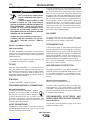
PRÉCAUTIONS DE SÛRETÉ
Pour votre propre protection lire et observer toutes les instructions
et les précautions de sûreté specifiques qui parraissent dans ce
manuel aussi bien que les précautions de sûreté générales suiv-
antes:
Sûreté Pour Soudage A LʼArc
1. Protegez-vous contre la secousse électrique:
a. Les circuits à lʼélectrode et à la piéce sont sous tension
quand la machine à souder est en marche. Eviter toujours
tout contact entre les parties sous tension et la peau nue
ou les vétements mouillés. Porter des gants secs et sans
trous pour isoler les mains.
b. Faire trés attention de bien sʼisoler de la masse quand on
soude dans des endroits humides, ou sur un plancher
metallique ou des grilles metalliques, principalement dans
les positions assis ou couché pour lesquelles une grande
partie du corps peut être en contact avec la masse.
c. Maintenir le porte-électrode, la pince de masse, le câble
de soudage et la machine à souder en bon et sûr état
defonctionnement.
d.Ne jamais plonger le porte-électrode dans lʼeau pour le
refroidir.
e. Ne jamais toucher simultanément les parties sous tension
des porte-électrodes connectés à deux machines à souder
parce que la tension entre les deux pinces peut être le
total de la tension à vide des deux machines.
f. Si on utilise la machine à souder comme une source de
courant pour soudage semi-automatique, ces precautions
pour le porte-électrode sʼapplicuent aussi au pistolet de
soudage.
2. Dans le cas de travail au dessus du niveau du sol, se protéger
contre les chutes dans le cas ou on recoit un choc. Ne jamais
enrouler le câble-électrode autour de nʼimporte quelle partie
du corps.
3. Un coup dʼarc peut être plus sévère quʼun coup de soliel,
donc:
a. Utiliser un bon masque avec un verre filtrant approprié
ainsi quʼun verre blanc afin de se protéger les yeux du ray-
onnement de lʼarc et des projections quand on soude ou
quand on regarde lʼarc.
b. Porter des vêtements convenables afin de protéger la
peau de soudeur et des aides contre le rayonnement de
lʻarc.
c. Protéger lʼautre personnel travaillant à proximité au
soudage à lʼaide dʼécrans appropriés et non-inflammables.
4. Des gouttes de laitier en fusion sont émises de lʼarc de
soudage. Se protéger avec des vêtements de protection libres
de lʼhuile, tels que les gants en cuir, chemise épaisse, pan-
talons sans revers, et chaussures montantes.
5. Toujours porter des lunettes de sécurité dans la zone de
soudage. Utiliser des lunettes avec écrans lateraux dans les
zones où lʼon pique le laitier.
6. Eloigner les matériaux inflammables ou les recouvrir afin de
prévenir tout risque dʼincendie dû aux étincelles.
7. Quand on ne soude pas, poser la pince à une endroit isolé de
la masse. Un court-circuit accidental peut provoquer un
échauffement et un risque dʼincendie.
8. Sʼassurer que la masse est connectée le plus prés possible
de la zone de travail quʼil est pratique de le faire. Si on place
la masse sur la charpente de la construction ou dʼautres
endroits éloignés de la zone de travail, on augmente le risque
de voir passer le courant de soudage par les chaines de lev-
age, câbles de grue, ou autres circuits. Cela peut provoquer
des risques dʼincendie ou dʼechauffement des chaines et des
câbles jusquʼà ce quʼils se rompent.
9. Assurer une ventilation suffisante dans la zone de soudage.
Ceci est particuliérement important pour le soudage de tôles
galvanisées plombées, ou cadmiées ou tout autre métal qui
produit des fumeés toxiques.
10. Ne pas souder en présence de vapeurs de chlore provenant
dʼopérations de dégraissage, nettoyage ou pistolage. La
chaleur ou les rayons de lʼarc peuvent réagir avec les vapeurs
du solvant pour produire du phosgéne (gas fortement toxique)
ou autres produits irritants.
11. Pour obtenir de plus amples renseignements sur la sûreté,
voir le code “Code for safety in welding and cutting” CSA
Standard W 117.2-1974.
PRÉCAUTIONS DE SÛRETÉ POUR
LES MACHINES À SOUDER À
TRANSFORMATEUR ET À
REDRESSEUR
1. Relier à la terre le chassis du poste conformement au code de
lʼélectricité et aux recommendations du fabricant. Le dispositif
de montage ou la piece à souder doit être branché à une
bonne mise à la terre.
2. Autant que possible, Iʼinstallation et lʼentretien du poste seront
effectués par un électricien qualifié.
3. Avant de faires des travaux à lʼinterieur de poste, la debranch-
er à lʼinterrupteur à la boite de fusibles.
4. Garder tous les couvercles et dispositifs de sûreté à leur
place.

v
SAFETY
v
Electromagnetic Compatibility (EMC)
Conformance
Products displaying the CE mark are in conformity with European Community Council Directive of 15 Dec
2004 on the approximation of the laws of the Member States relating to electromagnetic compatibility,
2004/108/EC. It was manufactured in conformity with a national standard that implements a harmonized
standard: EN 60974-10 Electromagnetic Compatibility (EMC) Product Standard for Arc Welding Equipment.
It is for use with other Lincoln Electric equipment. It is designed for industrial and professional use.
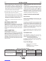
Introduction
All electrical equipment generates small amounts of electromagnetic emission. Electrical emission may be
transmitted through power lines or radiated through space, similar to a radio transmitter. When emissions
are received by other equipment, electrical interference may result. Electrical emissions may affect many
kinds of electrical equipment; other nearby welding equipment, radio and TV reception, numerical controlled
machines, telephone systems, computers, etc. Be aware that interference may result and extra precautions
may be required when a welding power source is used in a domestic establishment.
Installation and Use
The user is responsible for installing and using the welding equipment according to the manufacturer’s
instructions. If electromagnetic disturbances are detected then it shall be the responsibility of the user of the
welding equipment to resolve the situation with the technical assistance of the manufacturer. In some cases
this remedial action may be as simple as earthing (grounding) the welding circuit, see Note. In other cases it
could involve construction of an electromagnetic screen enclosing the power source and the work complete
with associated input filters. In all cases electromagnetic disturbances must be reduced to the point where
they are no longer troublesome.
Note: The welding circuit may or may not be earthed for safety reasons according to national codes.
Changing the earthing arrangements should only be authorized by a person who is compe-
tent to access whether the changes will increase the risk of injury, e.g., by allowing parallel
welding current return paths which may damage the earth circuits of other equipment.
Assessment of Area
Before installing welding equipment the user shall make an assessment of potential electromagnetic prob-
lems in the surrounding area. The following shall be taken into account:
a) other supply cables, control cables, signaling and telephone cables; above, below and adjacent to the
welding equipment;
b) radio and television transmitters and receivers;
c) computer and other control equipment;
d) safety critical equipment, e.g., guarding of industrial equipment;
e) the health of the people around, e.g., the use of pacemakers and hearing aids;
f) equipment used for calibration or measurement
g) the immunity of other equipment in the environment. The user shall ensure that other equipment being
used in the environment is compatible. This may require additional protection measures;
h) the time of day that welding or other activities are to be carried out.

vi
SAFETY
vi
Electromagnetic Compatibility (EMC)
The size of the surrounding area to be considered will depend on the structure of the building and other
activities that are taking place. The surrounding area may extend beyond the boundaries of the premises.
Methods of Reducing Emissions
Mains Supply
Welding equipment should be connected to the mains supply according to the manufacturer’s recommenda-
tions. If interference occurs, it may be necessary to take additional precautions such as filtering of the mains
supply. Consideration should be given to shielding the supply cable of permanently installed welding equip-
ment, in metallic conduit or equivalent. Shielding should be electrically continuous throughout its length. The
shielding should be connected to the welding power source so that good electrical contact is maintained
between the conduit and the welding power source enclosure.
Maintenance of the Welding Equipment
The welding equipment should be routinely maintained according to the manufacturer’s recommendations.
All access and service doors and covers should be closed and properly fastened when the welding equip-
ment is in operation. The welding equipment should not be modified in any way except for those changes
and adjustments covered in the manufacturers instructions. In particular, the spark gaps of arc striking and
stabilizing devices should be adjusted and maintained according to the manufacturer’s recommendations.
Welding Cables
The welding cables should be kept as short as possible and should be positioned close together, running at
or close to floor level.
Equipotential Bonding
Bonding of all metallic components in the welding installation and adjacent to it should be considered.
However, metallic components bonded to the work piece will increase the risk that the operator could
receive a shock by touching these metallic components and the electrode at the same time. The operator
should be insulated from all such bonded metallic components.
Earthing of the Workpiece
Where the workpiece is not bonded to earth for electrical safety, not connected to earth because of its size
and position, e.g., ships hull or building steelwork, a connection bonding the workpiece to earth may reduce
emissions in some, but not all instances. Care should be taken to prevent the earthing of the workpiece
increasing the risk of injury to users, or damage to other electrical equipment. Where necessary, the connec-
tion of the workpiece to earth should be made by a direct connection to the workpiece, but in some countries
where direct connection is not permitted, the bonding should be achieved by suitable capacitance, selected
according to national regulations.
Screening and Shielding
Selective screening and shielding of other cables and equipment in the surrounding area may alleviate prob-
lems of interference. Screening of the entire welding installation may be considered for special
applications1.
_________________________
1 Portions of the preceding text are contained in EN 60974-10: “Electromagnetic Compatibility (EMC) prod-
uct standard for arc welding equipment.”

viivii
Thank You for selecting a QUALITY product by Lincoln Electric. We want you
to take pride in operating this Lincoln Electric Company product
••• as much pride as we have in bringing this product to you!
Read this Operators Manual completely before attempting to use this equipment. Save this manual and keep it
handy for quick reference. Pay particular attention to the safety instructions we have provided for your protection.
The level of seriousness to be applied to each is explained below:
WARNING
This statement appears where the information must be followed exactly to avoid serious personal injury or loss of life.
This statement appears where the information must be followed to avoid minor personal injury or damage to this equipment.
CAUTION
Please Examine Carton and Equipment For Damage Immediately
When this equipment is shipped, title passes to the purchaser upon receipt by the carrier. Consequently, Claims
for material damaged in shipment must be made by the purchaser against the transportation company at the
time the shipment is received.
Please record your equipment identification information below for future reference. This information can be
found on your machine nameplate.
Product _________________________________________________________________________________
Model Number ___________________________________________________________________________
Code Number or Date Code_________________________________________________________________
Serial Number____________________________________________________________________________
Date Purchased___________________________________________________________________________
Where Purchased_________________________________________________________________________
Whenever you request replacement parts or information on this equipment, always supply the information you
have recorded above. The code number is especially important when identifying the correct replacement parts.
On-Line Product Registration
- Register your machine with Lincoln Electric either via fax or over the Internet.
• For faxing: Complete the form on the back of the warranty statement included in the literature packet
accompanying this machine and fax the form per the instructions printed on it.
• For On-Line Registration: Go to our
WEB SITE at www.lincolnelectric.com. Choose “Support” and then “Register
Your Product”. Please complete the form and submit your registration.
CUSTOMER ASSISTANCE POLICY
The business of The Lincoln Electric Company is manufacturing and selling high quality welding equipment, consumables, and cutting equip-
ment. Our challenge is to meet the needs of our customers and to exceed their expectations. On occasion, purchasers may ask Lincoln
Electric for advice or information about their use of our products. We respond to our customers based on the best information in our posses-
sion at that time. Lincoln Electric is not in a position to warrant or guarantee such advice, and assumes no liability, with respect to such infor-
mation or advice. We expressly disclaim any warranty of any kind, including any warranty of fitness for any customer’s particular purpose,
with respect to such information or advice. As a matter of practical consideration, we also cannot assume any responsibility for updating or
correcting any such information or advice once it has been given, nor does the provision of information or advice create, expand or alter any
warranty with respect to the sale of our products.
Lincoln Electric is a responsive manufacturer, but the selection and use of specific products sold by Lincoln Electric is solely within the control
of, and remains the sole responsibility of the customer. Many variables beyond the control of Lincoln Electric affect the results obtained in
applying these types of fabrication methods and service requirements.
Subject to Change – This information is accurate to the best of our knowledge at the time of printing. Please refer to www.lincolnelectric.com
for any updated information.

viii viii
TABLE OF CONTENTS
Page
Installation .......................................................................................................Section A
Technical Specifications ........................................................................................A-1
Safety Precautions ..........................................................................................A-2
Select Suitable Location..................................................................................A-2
Lifting...............................................................................................................A-2
Stacking ..........................................................................................................A-2
Environmental Limitations ...............................................................................A-2
Input and Grounding Connections ..................................................................A-2
High Frequency Protection ....................................................................................A-2
Recommended Electrode and Work Cable for arc Welding ..................................A-2
Electrical Connection ......................................................................................A-3
Work Connection.............................................................................................A-3
Remote Sense Lead Specification ..................................................................A-3
Product Specific Instructions...........................................................................A-3
Software Tools ................................................................................................A-3
Power Wave Manager.....................................................................................A-3
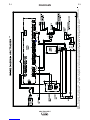
Connection Diagram-Electrode Positive................................................................A-4
________________________________________________________________________
Operation .........................................................................................................Section B
Safety Precautions.................................................................................................B-1
Graphic Symbols............................................................................................B-1, B-2
Product Description ...............................................................................................B-2
Design Features ....................................................................................................B-2
Recommended Processes and Equipment ...........................................................B-3
Common Equipment Packages .............................................................................B-3
Case Front Description..........................................................................................B-4
Case Back Controls...............................................................................................B-5
Power-Up Sequence..............................................................................................B-5
Duty Cycle .............................................................................................................B-5
Common Welding Procedures...............................................................................B-5
Set-Up Feature Menu ............................................................................................B-6
_______________________________________________________________________
Maintenance ....................................................................................................Section D
Safety Precautions ................................................................................................D-1
Routine Maintenance.............................................................................................D-1
Periodic Maintenance............................................................................................D-1
Calibration Specification........................................................................................D-1
Calibration Procedure..............................................................................D-2 thru D-3
________________________________________________________________________
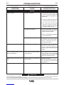
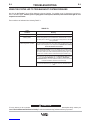
Section E ..............................................................................................Troubleshooting
Safety Precautions.................................................................................................E-1
How to Use Troubleshooting Guide.......................................................................E-1
Troubleshooting Guide ..........................................................................................E-2
________________________________________________________________________
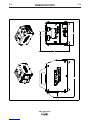
Wiring Diagram and Dimension Print ..............................................................Section F
________________________________________________________________________
Parts List ....................................................................................................P-675 Series
________________________________________________________________________

ARC TRACKER™
A-1
INSTALLATION
A-1
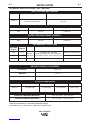
TECHNICAL SPECIFICATIONS -
ARC TRACKER™
RATED OPERATING RANGE NEMA EW1
INPUT VOLTAGE AND CURRENT
Model
K3019-1
Volts at Rated Amperes
44 V DC
Amperes
1000 A DC
Duty Cycle
100%
Input Amperes
0.8-0.5 A
Input Voltage ± 10%
120-230 V AC, 50/60 Hz
* All attachment plugs must comply with the Standard for Attachment Plugs and Receptacles, UL498.
RATED OPERATING RANGE IEC60974-1
Volts at Rated Amperes
44 V DC
Amperes
1000 A DC
Duty Cycle
100%
VOLTAGE
50/60 Hz
120
230
230
Input
Amperes
0.8 A
0.5 A
0.5 A
PLUG
NEMA 5-15P (INCLUDED)
ANY NEMA 250 V TYPE*
CEE 7/7
INPUT CORD
3 CONDUCTOR, #18 AWG
TYPE S, SO, SOO, ST, STO, STOO OR
EQUIVALENT EXTRA HARD USAGE CORD
3 CONDUCTOR, 1.0 mm2HAR
REGION
NORTH
AMERICA
EUROPE
RECOMMENDED INPUT WIRE
PHYSICAL DIMENSIONS
TEMPERATURE RANGES
HEIGHT
12 in (305 mm)
MODEL
K3019-1
WIDTH
9 in (220 mm)
DEPTH
15 in (380 mm)
WEIGHT
20 lbs ( 9 kg)
OPERATING TEMPERATURE RANGE
STORAGE TEMPERATURE RANGE
14°F TO 104°F (-10°C TO 40°C)
-40°F TO 185°F (-40°C TO 85°C)
VOLTMETER
AMMETER
ENERGY
± 2% + 0.1**
± 2% + 2**
± 5%
METER ACCURACY (AS SHIPPED)
**Accuracy is expressed as +/- [Percentage of Reading + Digits].
For example: 10A = +/- 10A x 0.02 + 2 = 10A +/- 2.2, or 7.8A to 12.2A

A-2
INSTALLATION
A-2
SELECT SUITABLE LOCATION
UNIT IS IP23 RATED.
The ARC TRACKER™ will operate in harsh environ-
ments. Even so, it is important that simple preventative
measures are followed in order to assure long life and
reliable operation.
• Keep machine dry. Shelter from rain and snow. Do
not place on wet ground or in puddles.
TILTING
Place the ARC TRACKER™ on a secure, level sur-
face. The weight of the welding cables hanging from
the connection terminals may cause the ARC TRACK-
ER™ to topple. Secure the welding cables to an
appropriate structure to reduce the hanging weight to
stabilize the ARC TRACKER™
STACKING
The ARC TRACKER™ cannot be stacked.
GROUNDING AND INPUT CONNECTIONS
MACHINE GROUNDING
The frame of the ARC TRACKER™ must be
grounded. By using the power cord shipped
with the unit, or by using a cord per the speci-
fications described here, the unit will be properly
grounded if connected to a grounded receptacle. See
your local and national electrical codes for proper
receptacle grounding methods.
INPUT CONNECTIONS
Installation should be made in accordance with the
appropriate National Electrical Code, all local codes
and the information in this manual.
SAFETY PRECAUTIONS
ELECTRIC SHOCK can kill.
• ONLY QUALIFIED PERSONNEL
SHOULD PERFORM THIS INSTAL-
LATION.
• TURN OFF INPUT POWER TO THE
POWER SOURCE AT THE DISCONNECT
SWITCH OR FUSE BOX BEFORE WORKING ON
THIS EQUIPMENT. TURN OFF THE INPUT
POWER TO ANY OTHER EQUIPMENT CON-
NECTED TO THE WELDING SYSTEM AT THE
DISCONNECT SWITCH OR FUSE BOX BEFORE
WORKING ON THE EQUIPMENT.
• DO NOT TOUCH ELECTRICALLY HOT PARTS.
• CONNECT THE ARC TRACKER™ TO AN OUT-
LET WITH PROPER SAFETY (EARTH)
GROUND.
----------------------------------------------------------------------
WARNING
ARC TRACKER™
The ARC TRACKER™ can be connected to 120 V AC
or 230 V AC, 50 or 60 Hz. The power supply inside
the unit can accept any single phase input voltage
from 120 V AC to 230 V AC. The unit is shipped from
the factory with a 6ft. (2m) detachable input cord with
a NEMA 5-15P plug and an IEC 60320 plug recepta-
cle. For the European market, it is suggested that an
input cord with a CEE 7/7 plug and IEC 60320 plug
receptacle be used. For all other regions, a cord
should be used with a plug which provides between
120 V AC and 230 V AC, 50 or 60Hz, and has the IEC
60320 plug receptacle. Cord must provide proper
ground per national electrical codes.
230 V INPUT
To change from 120 V to 230 V single phase input,
the NEMA 5-15P plug can be replaced by any NEMA
250 V type plug (for example – type 6-30P).
ATTACHMENT PLUG
In all cases, the green or green/yellow grounding wire
must be connected to the grounding pin of the plug,
usually identified by a green screw. All attachment
plugs must comply with the Standard for Attachment
Plugs and Receptacles, UL498. The product is con-
sidered acceptable for use only when an attachment
plug as specified is properly attached to the supply
cord. The ARC TRACKER™ will auto reconnect to
either 120 V or 230 V supplies.
HIGH FREQUENCY PROTECTION
The EMC classification of the ARC TRACKER™ is
Industrial, Scientific and Medical (ISM) group 2, class
A. The ARC TRACKER™ is for industrial use only.
(See Electromagnetic Compatibility EMC Safety
Section).
Harmonic Current Information:
Design complies with EN6100-3-2, -3.
Locate the ARC TRACKER™ away from radio con-
trolled machinery. The normal operation of the ARC
TRACKER™ may adversely affect the operation of RF
controlled equipment, which may result in bodily injury
or damage to the equipment.
RECOMMENDED ELECTRODE AND
WORK CABLE SIZES FOR ARC WELDING
General Guidelines
The following recommendations apply to all output
polarities and weld modes:

A-3
INSTALLATION
A-3
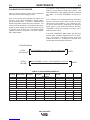
REMOTE SENSE LEAD SPECIFICATIONS
(See Figure A.1)
In order to get an accurate measurement of the true
energy going in to the weld, it is critical to get an
accurate measurement of the arc voltage. The arc
voltage sense leads are polarity specific – RED must
be connected to the positive side of the arc and
BLACK to the negative. The sense leads should be
connected as close as possible to the arc, e.g. at the
contact tip, wire feeder, etc and to the work.
PRODUCT SPECIFIC INSTRUCTIONS
Best Practices:
Place the ARC TRACKER™ in the work circuit. This
will keep the ARC TRACKER™ at the same potential
as the work piece.
The welding current MUST flow into the left side weld
terminals (when viewing the ARC TRACKER™ from
the rear) and out of the right side weld terminals. If the
welding current does not flow through the ARC
TRACKER™ in the right direction, the unit will not
properly sense the welding current and nothing will be
displayed on the unit during welding.
See the specific power source instruction manual for
additional general guidelines on output cable connec-
tions.
SOFTWARE TOOLS
ARC TRACKER™ software tools and other docu-
ments related to the integration, configuration, and
operation of the system are available at,
www.powerwavesoftware.com
An Ethernet connection gives the ARC TRACKER™
the ability to run Power Wave Manager and
Production Monitoring™.
Power Wave Manager
• Ethernet setup and verification
• Calibration
• Production Monitoring Configuration
• User Interface Lockout
ELECTRODE CONNECTIONS
Electrode Positive (See Figure A.1)
Connect cable(s) of sufficient size and length (Per
Table A.1) to the "ELECTRODE" terminals on the
power source. Connect the other end of the electrode
cable(s) to the contact tip, wire feeder, etc. Be sure
the connection makes tight metal-to-metal electrical
contact.
WORK CONNECTIONS
Electrode Positive (See Figure A.1)
Connect cable(s) of sufficient size and length (Per
Table A.1) between the "WORK" terminals on the
power source and the ARC TRACKER™ right side
weld terminals (when viewed from the rear). Connect
cable(s) of sufficient size and length from the ARC
TRACKER™ left weld terminals to the work. Be sure
the connection to the work makes tight metal-to-metal
electrical contact.
ARC TRACKER™
Total Cable Length ft (m)
Electrode and Work Combined
0 (0) to 250 (76.2)
Number of Cables
(parallel if more than one)
1
2
3
Current in Weld
Circuit
0-500 Amps
500-750 Amps
750-1000 Amps
Cable Size
(copper) AWG
4/0 (120 mm2)
4/0 (120 mm2)
3/0 (95 mm2)
Duty Cycle
100%
TABLE A.1 Output Cable Guidelines
• Select the appropriate size cables per the "Output
Cable Guidelines" Table A.1. Excessive voltage
drops caused by undersized welding cables and
poor connections often result in unsatisfactory weld-
ing performance. Always use the largest welding
cables (electrode and work) that are practical, and
be sure all connections are clean and tight.
Note: Excessive heat in the weld circuit indicates
undersized cables and/or bad connections.
• Route all cables directly to the work and electrode,
avoid excessive lengths and do not coil excess
cable. Route the electrode and work cables in close
proximity to one another to minimize the loop area
and therefore the inductance of the weld circuit.
• Always weld in a direction away from the work con-
nection.


B-1
OPERATION
ARC TRACKER™
B-1
SAFETY PRECAUTIONS
Read this entire section of operating instructions
before operating the machine.
ELECTRIC SHOCK can kill.
• Unless using cold feed feature, when
feeding with gun trigger, the
electrode and drive mechanism are
always electrically energized and
could remain energized several
seconds after the welding ceases.
• Do not touch electrically live parts or electrodes
with your skin or wet clothing.
• Insulate yourself from the work and ground.
• Always wear dry insulating gloves.
FUMES AND GASES can be
dangerous.
• Keep your head out of fumes.
• Use ventilation or exhaust to remove
fumes from breathing zone.
WELDING SPARKS can cause
fire or explosion.
• Keep flammable material away.
• Do not weld on containers that have
held combustibles.
ARC RAYS can burn.
• Wear eye, ear, and body protection.
Observe additional guidelines detailed in the
beginning of this manual.
WARNING
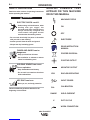
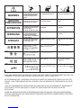
MACHINE STATUS
ON
WORK CONNECTION
OFF
ELECTRODE
READ INSTRUCTION
MANUAL
PROPER DISPOSAL
POSITIVE OUTPUT
NEGATIVE OUTPUT
ENCLOSURE RATING
INPUT POWER
CALIBRATION
WELD CURRENT
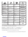
GRAPHIC SYMBOLS THAT
APPEAR ON THIS MACHINE
OR IN THIS MANUAL
RANGE
DUTY CYCLE
X
CAL
IP23

B-2
OPERATION
B-2
ARC TRACKER™
PRODUCT DESCRIPTION
General Functional Description
The ARC TRACKER™ is a high-performance,
portable product designed to accurately measure the
True Energy delivered into a weld from any welding
machine (DC process only). The ARC TRACKER™
will accurately measure the welding parameters (arc
voltage, arc current, and weld time) and provide a
real-time calculation of the True Energy into the weld.
While welding, the True Energy [in joules (J)] for the
weld will be accurately displayed on the user inter-
face.
The ARC TRACKER™ utilizes high-intensity LEDs
and alpha-numeric displays that can easily be seen
from a distance. The design uses advanced digital
controls to sample the welding parameters at a very
high rate of speed. The ARC TRACKER™ is compat-
ible with any DC welding process.
The ARC TRACKER™ has an Ethernet connector to
easily connect the product into a local network which
enables the use of Lincolnʼs additional software tools.
DESIGN FEATURES
• Multiple process DC welding range: 10-1000 Amps,
100% duty cycle.
• Simple Plug-N-Play design – connect to welding cir-
cuit, attach voltage sense leads and the meter
begins to function!
• Digital controls for highly accurate measurements.
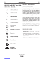
WELD AMPERAGE
INPUT VOLTAGE
WELD VOLTAGE
INPUT CURRENT
OUTPUT CURRENT
PROTECTIVE
GROUND
WARNING or CAUTION
Explosion
Dangerous Voltage
Shock Hazard
GRAPHIC SYMBOLS THAT
APPEAR ON THIS MACHINE
OR IN THIS MANUAL
A
U1
V
I1
I2
SET UP MENU
ETHERNET
CONNECTOR

B-3
OPERATION
B-3
RECOMMENDED PROCESSES AND
EQUIPMENT
RECOMMENDED PROCESSES
• DC arc welding circuits only
• Any welding process
• Any welding equipment
PROCESS LIMITATIONS
• Cannot be used with AC arc welding circuits
• 1000 A, 120 V, (maximums)
EQUIPMENT LIMITATIONS
• The weld terminals on the back of the ARC TRACK-
ER™ have a maximum threshold of welding current
which can flow through them. The correct number
and size of welding conductors must be used for
proper cooling. See the installation section for prop-
er connectivity.
• The ARC TRACKER™ has been calibrated before
being shipped from the factory. The Lincoln Electric
Company recommends that end-users of its welding
equipment evaluate the suitability of utilizing this
product in their quality system, determine if periodic
calibration is required and the calibration interval
based upon the criticality of the welding application,
the environment in which the equipment is located,
the level of preventive maintenance and the actual
conditions of use.
• The Ethernet connection gives the ARC TRACK-
ER™ the ability to run Production Monitoring™ with
certain function limitations, such as, no support for
wire feed speed, deposition rate, consumable pack-
age tracking and weldscore.
ARC TRACKER™

B-4
OPERATION
B-4
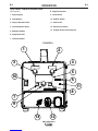
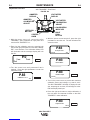
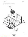
CASE FRONT CONTROL DESCRIPTIONS
(See Figure B.1)
1. Amps Display
2. Volts Display
3. Amps Calibration Knob
4. Volts Calibration Knob
5. Message Display
6. Setup Mode LED
7. Left Push Button
ARC TRACKER™
12
34
5
6
7
8
9
10
11
12
13
FIGURE B.1
8. Right Push button
9. Center Knob
10. ON/OFF Switch
11. Status LED
12. Ethernet Connector
13. Voltage Sense Lead Connector

B-5
OPERATION
B-5
ARC TRACKER™
POWER-UP SEQUENCE
When power is applied to the ARC TRACKER™, the
status light will flash green for up to 60 seconds.
During this time the unit is performing a self test. The
status light will also flash green as a result of a system
reset or configuration change during operation. When
the status light becomes steady green the system is
ready for use.
If the status light does not become steady green con-
sult the troubleshooting section of this manual for fur-
ther instruction.
DUTY CYCLE
The
ARC TRACKER™
is rated for 1000 A, 44 V DC,
100% duty cycle.
• Note: The correct number and size of welding con-
ductors must be used for proper cooling. See
the installation section for proper connectivity.
COMMON WELDING PROCEDURES
The ARC TRACKER™ can be used with any DC
welding process.
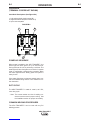
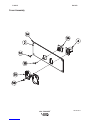
CASE BACK
(TERMINAL COVERS NOT SHOWN)
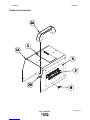
Case Back Descriptions (See Figure B.2)
1. Left weld terminals (weld current IN)
2. Right weld terminals (weld current OUT)
3. Input cord receptacle
12
3
FIGURE B.2

SETUP MENU FEATURES
The Setup Menu gives access to the Setup
Configuration. Stored in the setup configuration are
user parameters that generally only need to be set at
installation. The parameters are grouped as shown in
the following table.
SET-UP FEATURES MENU
(See Figure B.1)
1. To access the set-up menu, press the Right and
Left buttons of the Main Display panel simultane-
ously. Note that the set-up menu cannot be
accessed if there is a fault (The status LED is not
solid green).
Change the value of the blinking parameter by rotat-
ing the Center knob.
2. After changing a parameter it is necessary to press
the Right hand button to save the new setting.
Pressing the Left button will cancel the change.
3. To exit the set-up menu at any time, press the
Right and Left buttons of the Main Display panel
simultaneously. Alternately, 1 minute of inactivity
will also exit the set-up menu.
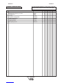
PARAMETER DEFINITION
P.1 through P.99 Unsecured Parameters
(always adjustable)
P.101 through P.199 Diagnostic Parameters
(always read only)
P.501 through P.599
Secured Parameters
(only accessible through a p.c.
application)
B-6
OPERATION
B-6
ARC TRACKER™
USER DEFINED PARAMETERS
Parameter Definition
Exit Setup Menu
P.0 This option is used to exit the setup menu. When P.0 is displayed, press the Left Button to exit
the setup menu.
P.83 Calibration
See Calibration Specification section for further details.
P.106 View Ethernet IP Address
Used for viewing the IP address of Ethernet compatible equipment. Press the Right Button to
read the IP Address. Press the Left Button to back out and exit this option. The IP address
cannot be changed using this option.
P.505 Setup Menu Lock
Determines if the setup parameters can be modified by the operator without entering a pass-
code.
No = The operator can change any set menu parameter without first entering the passcode
even if the passcode is non-zero (default).
Yes = The operator must enter the passcode (if the passcode is non-zero) in order to change
any setup menu parameters.
This parameter can only be accessed using Power Wave Manager software.
P.506 Set User Interface Passcode
Prevents unauthorized changes to the equipment. The default passcode is zero which allows
full access. A nonzero passcode will prevent unauthorized changes to setup parameters (if
P.505 = Yes).
This parameter can only be accessed using Power Wave Manager software.
P.509 UI Master Lockout
Locks all user interface controls, preventing the operator from making any changes. This para-
meter can only be accessed using Power Wave Manager software.

D-1
MAINTENANCE
D-1
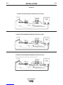
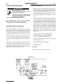
Required equipment:
• Power source to provide welding current and volt-
age. The power source should be capable of pro-
ducing the same level of welding current and volt-
age as the ARC TRACKER™ application. It is rec-
ommended to use the same power source used in
the welding application for this calibration proce-
dure.
• Calibrated reference volt meter, shunt and amme-
ter as in Figure D.1. The recommended accuracy
must be at least four times the desired accuracy of
the digital meters on the ARC TRACKER™ being
calibrated. Example, to obtain +/-2% accuracy, the
shunt accuracy and ammeter accuracy combina-
tion must be +/-0.5% accurate. The meters listed
below have been verified to produce accurate
results with inverter power sources. If other
meters are used, the compatibility and accuracy
with inverter power sources must be determined
by the user.
Volt meter: Keithley 2701 Digital Multimeter
Ammeter: Keithley 2701 Digital Multimeter
Shunt: GE 1000A/100mV Master Shunt
• Resistive Load, such as Lincoln Electric Master
Load 750 (750 A max).
• ARC TRACKER™ being calibrated.
• 4/0 welding cables
Test Setup:
Connect equipment as shown in Figure D.1.
ARC TRACKER™
SAFETY PRECAUTIONS
ELECTRIC SHOCK can kill.
• Only Qualified personnel should
perform this maintenance.
• Turn the input power OFF at the
disconnect switch or fuse box before
working on this equipment.
• Do not touch electrically hot parts.
------------------------------------------------------------------------
See additional warning information
throughout this Operatorʼs Manual
------------------------------------------------------------
WARNING
CALIBRATION SPECIFICATION
The ARC TRACKER™ as shipped from the factory
has +/-2% accuracy on the digital volts display and
amps display. Due to the heat input calculation being
a function of measured volts, amps, and arc on-time,
the displayed energy value has an accuracy of +/-5%.
The Lincoln Electric Company recommends that end-
users of its welding equipment evaluate the suitability
of utilizing the ARC TRACKER™ in their quality sys-
tem.
Determine if periodic calibration is required and the
calibration interval based upon the criticality of the
welding application, the environment in which the
equipment is located, the level of preventive mainte-
nance and the actual conditions of use.
FIGURE D.1
La page est en cours de chargement...
La page est en cours de chargement...
La page est en cours de chargement...
La page est en cours de chargement...
La page est en cours de chargement...
La page est en cours de chargement...
La page est en cours de chargement...
La page est en cours de chargement...
La page est en cours de chargement...
La page est en cours de chargement...
La page est en cours de chargement...
La page est en cours de chargement...
La page est en cours de chargement...
La page est en cours de chargement...
La page est en cours de chargement...
La page est en cours de chargement...
La page est en cours de chargement...
La page est en cours de chargement...
La page est en cours de chargement...
La page est en cours de chargement...
La page est en cours de chargement...
La page est en cours de chargement...
La page est en cours de chargement...
La page est en cours de chargement...
La page est en cours de chargement...
La page est en cours de chargement...
La page est en cours de chargement...
La page est en cours de chargement...
-
 1
1
-
 2
2
-
 3
3
-
 4
4
-
 5
5
-
 6
6
-
 7
7
-
 8
8
-
 9
9
-
 10
10
-
 11
11
-
 12
12
-
 13
13
-
 14
14
-
 15
15
-
 16
16
-
 17
17
-
 18
18
-
 19
19
-
 20
20
-
 21
21
-
 22
22
-
 23
23
-
 24
24
-
 25
25
-
 26
26
-
 27
27
-
 28
28
-
 29
29
-
 30
30
-
 31
31
-
 32
32
-
 33
33
-
 34
34
-
 35
35
-
 36
36
-
 37
37
-
 38
38
-
 39
39
-
 40
40
-
 41
41
-
 42
42
-
 43
43
-
 44
44
-
 45
45
-
 46
46
-
 47
47
-
 48
48


Lincoln Electric ARC TRACKER IM10090 Manuel utilisateur
- Catégorie
- Système de soudage
- Taper
- Manuel utilisateur
dans d''autres langues
Documents connexes
-
Lincoln Electric Ranger 305D Mode d'emploi
-
Lincoln Electric Power Wave 405M Mode d'emploi
-
-
-
-
Lincoln Electric AutoDrive 4R100 Mode d'emploi
-
-
-
-
Lincoln Electric POWER MIG 256 Manuel utilisateur