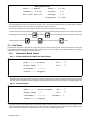
Miller LJ470011G Le manuel du propriétaire
- Catégorie
- Système de soudage
- Taper
- Le manuel du propriétaire
Ce manuel convient également à

ProHeat 35 CE
Processes
Description
Induction Heating Power Source
Induction Heating
OM-222 166L 2008−11
File: Induction Heating
Visit our website at
www.MillerWelds.com

Miller Electric manufactures a full line
of welders and welding related equipment.
For information on other quality Miller
products, contact your local Miller distributor to receive the latest full
line catalog or individual specification sheets. To locate your nearest
distributor or service agency call 1-800-4-A-Miller, or visit us at
www.MillerWelds.com on the web.
Thank you and congratulations on choosing Miller. Now you can get
the job done and get it done right. We know you don’t have time to do
it any other way.
That’s why when Niels Miller first started building arc welders in 1929,
he made sure his products offered long-lasting value and superior
quality. Like you, his customers couldn’t afford anything less. Miller
products had to be more than the best they could be. They had to be the
best you could buy.
Today, the people that build and sell Miller products continue the
tradition. They’re just as committed to providing equipment and service
that meets the high standards of quality and value established in 1929.
This Owner’s Manual is designed to help you get the most out of your
Miller products. Please take time to read the Safety precautions. They
will help you protect yourself against potential hazards on the worksite.
We’ve made installation and operation quick
and easy. With Miller you can count on years
of reliable service with proper maintenance.
And if for some reason the unit needs repair,
there’s a Troubleshooting section that will
help you figure out what the problem is. The
parts list will then help you to decide the
exact part you may need to fix the problem.
Warranty and service information for your
particular model are also provided.
Miller is the first welding
equipment manufacturer in
the U.S.A. to be registered to
the ISO 9001:2000 Quality
System Standard.
Working as hard as you do
− every power source from
Miller is backed by the most
hassle-free warranty in the
business.
From Miller to You
Mil_Thank 4/05

TABLE OF CONTENTS
SECTION 1 − SAFETY PRECAUTIONS − READ BEFORE USING 1. . . . . . . . . . . . . . . . . . . . . . . . . . . . . . . . . .
1-1. Symbol Usage 1. . . . . . . . . . . . . . . . . . . . . . . . . . . . . . . . . . . . . . . . . . . . . . . . . . . . . . . . . . . . . . . . . . . . . . . .
1-2. Induction Heating Hazards 1. . . . . . . . . . . . . . . . . . . . . . . . . . . . . . . . . . . . . . . . . . . . . . . . . . . . . . . . . . . . .
1-3. Additional Symbols for Installation, Operation, and Maintenance 2. . . . . . . . . . . . . . . . . . . . . . . . . . . . . .
1-4. California Proposition 65 Warnings 2. . . . . . . . . . . . . . . . . . . . . . . . . . . . . . . . . . . . . . . . . . . . . . . . . . . . . . .
1-5. Principal Safety Standards 3. . . . . . . . . . . . . . . . . . . . . . . . . . . . . . . . . . . . . . . . . . . . . . . . . . . . . . . . . . . . .
1-6. EMF Information 3. . . . . . . . . . . . . . . . . . . . . . . . . . . . . . . . . . . . . . . . . . . . . . . . . . . . . . . . . . . . . . . . . . . . . .
SECTION 2 − CONSIGNES DE SÉCURITÉ − LIRE AVANT UTILISATION 4. . . . . . . . . . . . . . . . . . . . . . . . . . . .
2-1. Signification des symboles 4. . . . . . . . . . . . . . . . . . . . . . . . . . . . . . . . . . . . . . . . . . . . . . . . . . . . . . . . . . . . .
2-2. Dangers relatifs au soudage à l’arc 4. . . . . . . . . . . . . . . . . . . . . . . . . . . . . . . . . . . . . . . . . . . . . . . . . . . . . .
2-3. Dangers supplémentaires en relation avec l’installation, le fonctionnement et la maintenance 5. . . . . .
2-4. Proposition californienne 65 Avertissements 6. . . . . . . . . . . . . . . . . . . . . . . . . . . . . . . . . . . . . . . . . . . . . . .
2-5. Principales normes de sécurité 6. . . . . . . . . . . . . . . . . . . . . . . . . . . . . . . . . . . . . . . . . . . . . . . . . . . . . . . . . .
2-6. Information EMF 6. . . . . . . . . . . . . . . . . . . . . . . . . . . . . . . . . . . . . . . . . . . . . . . . . . . . . . . . . . . . . . . . . . . . . .
SECTION 3 − DEFINITIONS 7. . . . . . . . . . . . . . . . . . . . . . . . . . . . . . . . . . . . . . . . . . . . . . . . . . . . . . . . . . . . . . . . . . .
3-1. Warning Label Definitions 7. . . . . . . . . . . . . . . . . . . . . . . . . . . . . . . . . . . . . . . . . . . . . . . . . . . . . . . . . . . . . .
3-2. Warning Label Definitions (Continued) 8. . . . . . . . . . . . . . . . . . . . . . . . . . . . . . . . . . . . . . . . . . . . . . . . . . . .
3-3. WEEE Label (For Products Sold Within The EU) 9. . . . . . . . . . . . . . . . . . . . . . . . . . . . . . . . . . . . . . . . . . .
3-4. Symbols And Definitions 9. . . . . . . . . . . . . . . . . . . . . . . . . . . . . . . . . . . . . . . . . . . . . . . . . . . . . . . . . . . . . . .
SECTION 4 − INSTALLATION 10. . . . . . . . . . . . . . . . . . . . . . . . . . . . . . . . . . . . . . . . . . . . . . . . . . . . . . . . . . . . . . . . . .
4-1. Serial Number and Rating Label Location 10. . . . . . . . . . . . . . . . . . . . . . . . . . . . . . . . . . . . . . . . . . . . . . . . .
4-2. Specifications 10. . . . . . . . . . . . . . . . . . . . . . . . . . . . . . . . . . . . . . . . . . . . . . . . . . . . . . . . . . . . . . . . . . . . . . . .
4-3. Selecting A Location 10. . . . . . . . . . . . . . . . . . . . . . . . . . . . . . . . . . . . . . . . . . . . . . . . . . . . . . . . . . . . . . . . . . .
4-4. Tipping 11. . . . . . . . . . . . . . . . . . . . . . . . . . . . . . . . . . . . . . . . . . . . . . . . . . . . . . . . . . . . . . . . . . . . . . . . . . . . . .
4-5. Electrical Service Guide 11. . . . . . . . . . . . . . . . . . . . . . . . . . . . . . . . . . . . . . . . . . . . . . . . . . . . . . . . . . . . . . . .
4-6. Connecting 3-Phase Input Power For 460/575 Volt Models 12. . . . . . . . . . . . . . . . . . . . . . . . . . . . . . . . . . .
4-7. Connecting 3-Phase Input Power For 400/460 Volt Models 13. . . . . . . . . . . . . . . . . . . . . . . . . . . . . . . . . . .
4-8. Power Source Output Connections 14. . . . . . . . . . . . . . . . . . . . . . . . . . . . . . . . . . . . . . . . . . . . . . . . . . . . . .
4-9. Remote 14 Receptacle RC14 Information and Connections 15. . . . . . . . . . . . . . . . . . . . . . . . . . . . . . . . . .
4-10. Remote 14 Socket Information 15. . . . . . . . . . . . . . . . . . . . . . . . . . . . . . . . . . . . . . . . . . . . . . . . . . . . . . . . . .
4-11. Temperature Recorder Receptacle RC9 Information And Connections 16. . . . . . . . . . . . . . . . . . . . . . . . .
4-12. Temperature Recorder Socket Information 16. . . . . . . . . . . . . . . . . . . . . . . . . . . . . . . . . . . . . . . . . . . . . . . .
4-13. Secondary Insulation Protection 17. . . . . . . . . . . . . . . . . . . . . . . . . . . . . . . . . . . . . . . . . . . . . . . . . . . . . . . . .
4-14. 115 Volt AC Duplex Receptacle And Supplementary Protector 18. . . . . . . . . . . . . . . . . . . . . . . . . . . . . . . .
4-15. Locating Thermocouples 18. . . . . . . . . . . . . . . . . . . . . . . . . . . . . . . . . . . . . . . . . . . . . . . . . . . . . . . . . . . . . . .
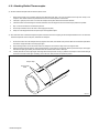
4-16. Attaching Welded Thermocouples 20. . . . . . . . . . . . . . . . . . . . . . . . . . . . . . . . . . . . . . . . . . . . . . . . . . . . . . .
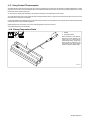
4-17. Using Contact Thermocouples 21. . . . . . . . . . . . . . . . . . . . . . . . . . . . . . . . . . . . . . . . . . . . . . . . . . . . . . . . . .
4-18. Placing Temperature Probe 21. . . . . . . . . . . . . . . . . . . . . . . . . . . . . . . . . . . . . . . . . . . . . . . . . . . . . . . . . . . . .
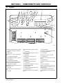
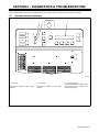
SECTION 5 − COMPONENTS AND CONTROLS 22. . . . . . . . . . . . . . . . . . . . . . . . . . . . . . . . . . . . . . . . . . . . . . . . . .
5-1. Controls 22. . . . . . . . . . . . . . . . . . . . . . . . . . . . . . . . . . . . . . . . . . . . . . . . . . . . . . . . . . . . . . . . . . . . . . . . . . . . .

TABLE OF CONTENTS
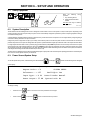
SECTION 6 − SETUP AND OPERATION 23. . . . . . . . . . . . . . . . . . . . . . . . . . . . . . . . . . . . . . . . . . . . . . . . . . . . . . . .
6-1. Safety Equipment 23. . . . . . . . . . . . . . . . . . . . . . . . . . . . . . . . . . . . . . . . . . . . . . . . . . . . . . . . . . . . . . . . . . . . .
6-2. System Description 23. . . . . . . . . . . . . . . . . . . . . . . . . . . . . . . . . . . . . . . . . . . . . . . . . . . . . . . . . . . . . . . . . . .
6-3. Power Source/System Setup 23. . . . . . . . . . . . . . . . . . . . . . . . . . . . . . . . . . . . . . . . . . . . . . . . . . . . . . . . . . .
6-4. Programming 25. . . . . . . . . . . . . . . . . . . . . . . . . . . . . . . . . . . . . . . . . . . . . . . . . . . . . . . . . . . . . . . . . . . . . . . . .
6-4-1. Temperature-Based Control 25. . . . . . . . . . . . . . . . . . . . . . . . . . . . . . . . . . . . . . . . . . . . . . . . . . . . . . . . . .
6-4-1-1. Preheat 25. . . . . . . . . . . . . . . . . . . . . . . . . . . . . . . . . . . . . . . . . . . . . . . . . . . . . . . . . . . . . . . . . . . . . . .
6-4-1-2. Bake-Out 26. . . . . . . . . . . . . . . . . . . . . . . . . . . . . . . . . . . . . . . . . . . . . . . . . . . . . . . . . . . . . . . . . . . . . .
6-4-1-3. PWHT (Post-Weld Heat Treat) 26. . . . . . . . . . . . . . . . . . . . . . . . . . . . . . . . . . . . . . . . . . . . . . . . . . . .
6-4-1-4. Custom Program 27. . . . . . . . . . . . . . . . . . . . . . . . . . . . . . . . . . . . . . . . . . . . . . . . . . . . . . . . . . . . . . . .
6-4-2. Manual Control 31. . . . . . . . . . . . . . . . . . . . . . . . . . . . . . . . . . . . . . . . . . . . . . . . . . . . . . . . . . . . . . . . . . . . .
6-5. Run Status 32. . . . . . . . . . . . . . . . . . . . . . . . . . . . . . . . . . . . . . . . . . . . . . . . . . . . . . . . . . . . . . . . . . . . . . . . . . .
6-5-1. Temperature Based Control 32. . . . . . . . . . . . . . . . . . . . . . . . . . . . . . . . . . . . . . . . . . . . . . . . . . . . . . . . . .
6-5-1-1. Preheat, Bake-Out And PWHT Run Status Screen 32. . . . . . . . . . . . . . . . . . . . . . . . . . . . . . . . . . .
6-5-1-2. Custom Program 32. . . . . . . . . . . . . . . . . . . . . . . . . . . . . . . . . . . . . . . . . . . . . . . . . . . . . . . . . . . . . . . .
6-5-2. Manual Control 33. . . . . . . . . . . . . . . . . . . . . . . . . . . . . . . . . . . . . . . . . . . . . . . . . . . . . . . . . . . . . . . . . . . . .
6-6. Parameters 33. . . . . . . . . . . . . . . . . . . . . . . . . . . . . . . . . . . . . . . . . . . . . . . . . . . . . . . . . . . . . . . . . . . . . . . . . .
6-7. Cooler 33. . . . . . . . . . . . . . . . . . . . . . . . . . . . . . . . . . . . . . . . . . . . . . . . . . . . . . . . . . . . . . . . . . . . . . . . . . . . . .
6-8. Real-Time Operation 34. . . . . . . . . . . . . . . . . . . . . . . . . . . . . . . . . . . . . . . . . . . . . . . . . . . . . . . . . . . . . . . . . .
6-9. System Operating Characteristics 36. . . . . . . . . . . . . . . . . . . . . . . . . . . . . . . . . . . . . . . . . . . . . . . . . . . . . . .
SECTION 7 − MAINTENANCE 37. . . . . . . . . . . . . . . . . . . . . . . . . . . . . . . . . . . . . . . . . . . . . . . . . . . . . . . . . . . . . . . . .
7-1. Routine Maintenance 37. . . . . . . . . . . . . . . . . . . . . . . . . . . . . . . . . . . . . . . . . . . . . . . . . . . . . . . . . . . . . . . . . .
7-2. Calibration Verification Equipment 38. . . . . . . . . . . . . . . . . . . . . . . . . . . . . . . . . . . . . . . . . . . . . . . . . . . . . . .
7-3. Calibration Verification Procedure 38. . . . . . . . . . . . . . . . . . . . . . . . . . . . . . . . . . . . . . . . . . . . . . . . . . . . . . . .
7-3-1. Initial Set Up 38. . . . . . . . . . . . . . . . . . . . . . . . . . . . . . . . . . . . . . . . . . . . . . . . . . . . . . . . . . . . . . . . . . . . . . .
7-3-2. TC Input/Output Check 38. . . . . . . . . . . . . . . . . . . . . . . . . . . . . . . . . . . . . . . . . . . . . . . . . . . . . . . . . . . . . .
7-3-3. Finishing Procedure 38. . . . . . . . . . . . . . . . . . . . . . . . . . . . . . . . . . . . . . . . . . . . . . . . . . . . . . . . . . . . . . . .
SECTION 8 − SAFETY PRECAUTIONS FOR SERVICING 43. . . . . . . . . . . . . . . . . . . . . . . . . . . . . . . . . . . . . . . . . .
8-1. Symbol Usage 43. . . . . . . . . . . . . . . . . . . . . . . . . . . . . . . . . . . . . . . . . . . . . . . . . . . . . . . . . . . . . . . . . . . . . . . .
8-2. Servicing Hazards 43. . . . . . . . . . . . . . . . . . . . . . . . . . . . . . . . . . . . . . . . . . . . . . . . . . . . . . . . . . . . . . . . . . . .
8-3. California Proposition 65 Warnings 44. . . . . . . . . . . . . . . . . . . . . . . . . . . . . . . . . . . . . . . . . . . . . . . . . . . . . . .
8-4. EMF Information 44. . . . . . . . . . . . . . . . . . . . . . . . . . . . . . . . . . . . . . . . . . . . . . . . . . . . . . . . . . . . . . . . . . . . . .
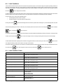
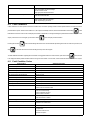
SECTION 9 − DIAGNOSTICS & TROUBLESHOOTING 45. . . . . . . . . . . . . . . . . . . . . . . . . . . . . . . . . . . . . . . . . . . .
9-1. Operator Interface Indicators 45. . . . . . . . . . . . . . . . . . . . . . . . . . . . . . . . . . . . . . . . . . . . . . . . . . . . . . . . . . . .
9-2. Limit Conditions 46. . . . . . . . . . . . . . . . . . . . . . . . . . . . . . . . . . . . . . . . . . . . . . . . . . . . . . . . . . . . . . . . . . . . . . .
9-3. Limit Condition Codes 46. . . . . . . . . . . . . . . . . . . . . . . . . . . . . . . . . . . . . . . . . . . . . . . . . . . . . . . . . . . . . . . . .
9-4. Fault Conditions 47. . . . . . . . . . . . . . . . . . . . . . . . . . . . . . . . . . . . . . . . . . . . . . . . . . . . . . . . . . . . . . . . . . . . . .
9-5. Fault Condition Codes 47. . . . . . . . . . . . . . . . . . . . . . . . . . . . . . . . . . . . . . . . . . . . . . . . . . . . . . . . . . . . . . . . .
9-6. System Diagnostic Screens 48. . . . . . . . . . . . . . . . . . . . . . . . . . . . . . . . . . . . . . . . . . . . . . . . . . . . . . . . . . . .
9-7. Removing Wrapper and Measuring Input Capacitor Voltage 50. . . . . . . . . . . . . . . . . . . . . . . . . . . . . . . . . .
9-8. Blowing Out Inside Of Unit 51. . . . . . . . . . . . . . . . . . . . . . . . . . . . . . . . . . . . . . . . . . . . . . . . . . . . . . . . . . . . . .
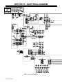
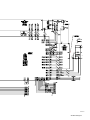
SECTION 10 − ELECTRICAL DIAGRAM 52. . . . . . . . . . . . . . . . . . . . . . . . . . . . . . . . . . . . . . . . . . . . . . . . . . . . . . . . .
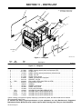
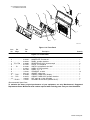
SECTION 11 − PARTS LIST 54. . . . . . . . . . . . . . . . . . . . . . . . . . . . . . . . . . . . . . . . . . . . . . . . . . . . . . . . . . . . . . . . . . . .
WARRANTY

240667A
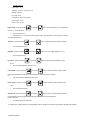
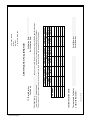
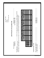
DECLARATION OF CONFORMITY
for European Community (CE marked) products.
MILLER Electric Mfg. Co., 1635 Spencer Street, Appleton, WI 54914 U.S.A. declares that
the product(s) identified in this declaration conform to the essential requirements and
provisions of the stated Council Directive(s) and Standard(s).
Product/Apparatus Identification:
Product Stock Number
PROHEAT 35 W/TEMPERATURE CONTROL 400460V, CE
907298
Council Directives:
S 2006/95/EC Low Voltage
S 2004/108/EC Electromagnetic Compatibility
S 2006/42/EEC Machinery Directive
Standards:
S IEC 60974-1 Arc Welding Equipment - Welding Power Sources: edition 3, 2005-07.
S IEC 60974-10 Arc Welding Equipment Electromagnetic Compatibility Requirements: edition 1.1,
2004-10.
US Signatory:
November 26, 2008
__________________________________________________________________________
David A. Werba
Date of Declaration
MANAGER, PRODUCT DESIGN COMPLIANCE


OM-222 166 Page 1
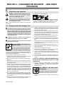
SECTION 1 − SAFETY PRECAUTIONS − READ BEFORE USING
ihom _2007−04
Protect yourself and others from injury — read and follow these precautions.
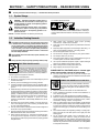
1-1. Symbol Usage
DANGER! − Indicates a hazardous situation which, if
not avoided, will result in death or serious injury. The
possible hazards are shown in the adjoining symbols
or explained in the text.
Indicates a hazardous situation which, if not avoided,
could result in death or serious injury. The possible
hazards are shown in the adjoining symbols or ex-
plained in the text.
NOTICE − Indicates statements not related to personal injury.
. Indicates special instructions.
This group of symbols means Warning! Watch Out! ELECTRIC
SHOCK, MOVING PARTS, and HOT PARTS hazards. Consult sym-
bols and related instructions below for necessary actions to avoid the
hazards.
1-2. Induction Heating Hazards
The symbols shown below are used throughout this manual
to call attention to and identify possible hazards. When you
see the symbol, watch out, and follow the related instructions
to avoid the hazard. The safety information given below is
only a summary of the more complete safety information
found in the Safety Standards listed in Section 1-5. Read and
follow all Safety Standards.
Only qualified persons should install, operate, maintain, and
repair this unit.
During operation, keep everybody, especially children, away.
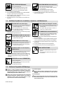
ELECTRIC SHOCK can kill.
Touching live electrical parts can cause fatal shocks
or severe burns. The power circuit and output bus
bars or connections are electrically live whenever
the output is on. The input power circuit and machine
internal circuits are also live when power is on. Incorrectly installed or
improperly grounded equipment is a hazard.
D Do not touch live electrical parts.
D Enclose any connecting bus bars and coolant fittings to prevent
unintentional contact.
D Wear dry, hole-free insulating gloves and body protection.
D Insulate yourself from work and ground using dry insulating mats or
covers big enough to prevent any physical contact with the work or
ground.
D Additional safety precautions are required when any of the follow-
ing electrically hazardous conditions are present: in damp locations
or while wearing wet clothing; on metal structures such as floors,
gratings, or scaffolds; when in cramped positions such as sitting,
kneeling, or lying; or when there is a high risk of unavoidable or ac-
cidental contact with the workpiece or ground. For these
conditions, see ANSI Z49.1 listed in Safety Standards. And, do not
work alone!
D Disconnect input power before installing or servicing this equip-
ment. Lockout/tagout input power according to OSHA 29 CFR
1910.147 (see Safety Standards).
D Use only nonconductive coolant hoses with a minimum length of 18
inches (457 mm) to provide isolation.
D Properly install and ground this equipment according to its Owner’s
Manual and national, state, and local codes.
D Always verify the supply ground − check and be sure that input pow-
er cord ground wire is properly connected to ground terminal in
disconnect box or that cord plug is connected to a properly grounded
receptacle outlet.
D When making input connections, attach proper grounding
conductor first − double-check connections.
D Keep cords dry, free of oil and grease, and protected from hot metal
and sparks.
D Frequently inspect input power cord for damage or bare wiring − re-
place cord immediately if damaged − bare wiring can kill.
D Turn off all equipment when not in use.
D Do not use worn, damaged, undersized, or poorly spliced cables.
D Do not drape cables over your body.
D Do not touch power circuit if you are in contact with the work, ground,
or another power circuit from a different machine.
D Use only well-maintained equipment. Repair or replace damaged
parts at once. Maintain unit according to manual.
D Wear a safety harness if working above floor level.
D Keep all panels and covers securely in place.
SIGNIFICANT DC VOLTAGE exists in inverter-type
power sources after removal of input power.
D Turn Off inverter, disconnect input power, and discharge input
capacitors according to instructions in Maintenance Section before
touching any internal parts.
Induction Heating of certain materials, adhesives,
and fluxes can produce fumes and gases. Breathing
these fumes and gases can be hazardous to your
health.
FUMES AND GASES can be hazardous.
D Keep your head out of the fumes. Do not breathe the fumes.
D If inside, ventilate the area and/or use local forced ventilation to re-
move fumes and gases.
D If ventilation is poor, wear an approved air-supplied respirator.
D Read and understand the Material Safety Data Sheets (MSDSs)
and the manufacturer’s instruction for adhesives, fluxes, metals,
consumables, coatings, cleaners, and degreasers.
D Work in a confined space only if it is well ventilated, or while wearing
an air-supplied respirator. Always have a trained watchperson near-
by. Fumes and gases from heating can displace air and lower the
oxygen level causing injury or death. Be sure the breathing air is
safe.
D Do not heat in locations near degreasing, cleaning, or spraying oper-
ations. The heat can react with vapors to form highly toxic and
irritating gases.
D Do not overheat coated metals, such as galvanized, lead, or
cadmium plated steel, unless the coating is removed from the
heated area, the area is well ventilated, and while wearing an air-
supplied respirator. The coatings and any metals containing these
elements can give off toxic fumes if overheated. See coating MSDS
for temperature information.

OM-222 166 Page 2
FIRE OR EXPLOSION hazard.
D Do not overheat parts.
D Watch for fire; keep extinguisher nearby.
D Keep flammables away from work area.
D Do not locate unit on, over, or near combustible surfaces.
D Do not install unit near flammables.
D Do not operate where the atmosphere may contain flammable
dust, gas, or liquid vapors (such as gasoline).
D After completion of work, inspect area to ensure it is free of
sparks, glowing embers, and flames.
D Use only correct fuses or circuit breakers. Do not oversize or by-
pass them.
INDUCTION HEATING can cause burns.
D Hot parts and equipment can injure.
D Do not touch or handle induction head/coil
during operation.
D Do not touch hot parts bare-handed.
D Allow cooling period before handling parts or equipment.
D Keep metal jewelry and other metal personal items away from
head/coil during operation.
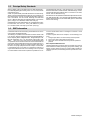
1-3. Additional Symbols for Installation, Operation, and Maintenance
FALLING UNIT can cause injury.
D Use handle and have person of adequate
physical strength lift unit.
D Move unit with hand cart or similar device.
D For units without a handle, use equipment of
adequate capacity to lift unit.
D When using lift forks to move unit, be sure forks are long enough
to extend beyond opposite side of unit.
FLYING METAL OR DIRT can injure eyes.
D Wear approved safety glasses with side
shields or wear face shield.
MOVING PARTS can cause injury.
D Keep away from moving parts such as fans.
D Keep all doors, panels, covers, and guards
closed and securely in place.
MAGNETIC FIELDS can affect Implanted
Medical Devices.
D Wearers of Pacemakers and other Implanted
Medical Devices should keep away.
D Implanted Medical Device wearers should consult their doctor
and the device manufacturer before going near arc welding, spot
welding, gouging, plasma arc cutting, or induction heating
operations.
OVERUSE can cause OVERHEATING
D Allow cooling period.
D Reduce output or reduce duty cycle before
starting to heat again.
D Follow rated duty cycle.
STATIC (ESD) can damage PC boards.
D Put on grounded wrist strap BEFORE handling
boards or parts.
D Use proper static-proof bags and boxes to
store, move, or ship PC boards.
H.F. RADIATION can cause interference.
D High-frequency (H.F.) can interfere with radio
navigation, safety services, computers, and
communications equipment.
D Have only qualified person familiar with electronic equipment per-
form this installation.
D The user is responsible for having a qualified electrician promptly
correct any interference problem resulting from the installation.
D If notified by the FCC about interference, stop using the equip-
ment at once.
D Have the installation regularly checked and maintained.
D Keep high-frequency source doors and panels tightly shut.
READ INSTRUCTIONS.
D Read Owner’s Manual before using or servic-
ing unit.
D Use only genuine replacement parts from the
manufacturer.
1-4. California Proposition 65 Warnings
Welding or cutting equipment produces fumes or gases
which contain chemicals known to the State of California to
cause birth defects and, in some cases, cancer. (California
Health & Safety Code Section 25249.5 et seq.)
Battery posts, terminals and related accessories contain lead
and lead compounds, chemicals known to the State of
California to cause cancer and birth defects or other
reproductive harm. Wash hands after handling.
For Gasoline Engines:
Engine exhaust contains chemicals known to the State of
California to cause cancer, birth defects, or other reproduc-
tive harm.
For Diesel Engines:
Diesel engine exhaust and some of its constituents are known
to the State of California to cause cancer, birth defects, and
other reproductive harm.

OM-222 166 Page 3
1-5. Principal Safety Standards
Safety in Welding, Cutting, and Allied Processes, ANSI Standard Z49.1,
from Global Engineering Documents (phone: 1-877-413-5184, website:
www.global.ihs.com).
OSHA, Occupational Safety and Health Standards for General Industry,
Title 29, Code of Federal Regulations (CFR), Part 1910, Subpart Q, and
Part 1926, Subpart J, from U.S. Government Printing Office, Superinten-
dent of Documents, P.O. Box 371954, Pittsburgh, PA 15250-7954
(phone: 1-866-512-1800) (there are 10 Regional Offices—phone for Re-
gion 5, Chicago, is 312-353-2220, website: www.osha.gov).
National Electrical Code, NFPA Standard 70, from National Fire Protec-
tion Association, P.O. Box 9101, Quincy, MA 02269-9101 (phone:
617-770-3000, website: www.nfpa.org and www. sparky.org).
Canadian Electrical Code Part 1, CSA Standard C22.1, from Canadian
Standards Association, Standards Sales, 5060 Mississauga, Ontario,
Canada L4W 5NS (phone: 800-463-6727 or in Toronto 416-747-4044,
website: www.csa-international.org).
Safe Practice For Occupational And Educational Eye And Face Protec-
tion, ANSI Standard Z87.1, from American National Standards Institute,
25 West 43rd Street, New York, NY 10036–8002 (phone: 212-642-4900,
website: www.ansi.org).
1-6. EMF Information
Considerations About Induction Heating And The Effects Of Low Fre-
quency Electric And Magnetic Fields
The following is a quotation from the General Conclusions Section of the
U.S. Congress, Office of Technology Assessment, Biological Effects of
Power Frequency Electric & Magnetic Fields − Background Paper, OTA-
BP-E-53 (Washington, DC: U.S. Government Printing Office, May
1989): “. . . there is now a very large volume of scientific findings based
on experiments at the cellular level and from studies with animals and
people which clearly establish that low frequency magnetic fields can in-
teract with, and produce changes in, biological systems. While most of
this work is of very high quality, the results are complex. Current scientif-
ic understanding does not yet allow us to interpret the evidence in a
single coherent framework. Even more frustrating, it does not yet allow
us to draw definite conclusions about questions of possible risk or to of-
fer clear science-based advice on strategies to minimize or avoid
potential risks.”
To reduce magnetic fields in the workplace, use the following proce-
dures:
1. Arrange output cable to one side and away from the operator.
2. Do not coil or drape output cable around the body.
3. Keep power source and cable as far away from the operator as
practical.
About Implanted Medical Devices:
Implanted Medical Device wearers should consult their doctor and the
device manufacturer before performing or going near arc welding, spot
welding, gouging, plasma arc cutting, or induction heating operations. If
cleared by your doctor, then following the above procedures is recom-
mended.

OM-222 166 Page 4
SECTION 2 − CONSIGNES DE SÉCURITÉ − LIRE AVANT
UTILISATION
ihom _2007−04fre
Se protéger, ainsi que toute autre personne travaillant sur les lieux, contre les étincelles et le métal chaud.
2-1. Signification des symboles
DANGER! − Indique une situation dangereuse qui si on
l’évite pas peut donner la mort ou des blessures graves.
Les dangers possibles sont montrés par les symboles
joints ou sont expliqués dans le texte.
Indique une situation dangereuse qui si on l’évite pas
peut donner la mort ou des blessures graves. Les dan-
gers possibles sont montrés par les symboles joints ou
sont expliqués dans le texte.
NOTE − Indique des déclarations pas en relation avec des blessures
personnelles.
. Indique des instructions spécifiques.
Ce groupe de symboles veut dire Avertissement! Attention! DANGER
DE CHOC ELECTRIQUE, PIECES EN MOUVEMENT, et PIECES
CHAUDES. Consulter les symboles et les instructions ci-dessous y
afférant pour les actions nécessaires afin d’éviter le danger.
2-2. Dangers relatifs au soudage à l’arc
Les symboles présentés ci-après sont utilisés tout au long du
présent manuel pour attirer votre attention et identifier les ris-
ques de danger. Lorsque vous voyez un symbole, soyez
vigilant et suivez les directives mentionnées afin d’éviter tout
danger. Les consignes de sécurité présentées ci-après ne font
que résumer l’information contenue dans les normes de sécu-
rité énumérées à la section 2-5. Veuillez lire et respecter toutes
ces normes de sécurité.
L’installation, l’utilisation, l’entretien et les réparations ne
doivent être confiés qu’à des personnes qualifiées.
Au cours de l’utilisation, tenir toute personne à l’écart et plus
particulièrement les enfants.
UNE DÉCHARGE ÉLECTRIQUE peut
entraîner la mort.
Le contact de composants électriques peut provo-
quer des accidents mortels ou des brûlures graves.
Le circuit électrique et les barres collectrices ou les
connexions de sortie sont sous tension lorsque
l’appareil fonctionne. Le circuit d’alimentation et les circuits internes
de la machine sont également sous tension lorsque l’alimentation est
sur marche. Des équipements installés ou reliés à la borne de terre de
manière incorrecte sont dangereux.
D Ne pas toucher aux pièces électriques sous tension.
D Protéger toutes les barres collectrices et les raccords de refroidis-
sement pour éviter de les toucher par inadvertance.
D Porter des gants isolants et des vêtements de protection secs et
sans trous.
D S’isoler de la pièce à couper et du sol en utilisant des housses ou
des tapis assez grands afin d’éviter tout contact physique avec la
pièce à couper ou le sol.
D D’autres consignes de sécurité sont nécessaires dans les conditions
suivantes : risques électriques dans un environnement humide ou si
l’on porte des vêtements mouillés ; sur des structures métalliques telles
que sols, grilles ou échafaudages ; en position coincée comme assi-
se, à genoux ou couchée ; ou s’il y a un risque élevé de contact
inévitable ou accidentel avec la pièce à souder ou le sol. Dans ces
conditions, voir ANSI Z49.1 énuméré dans les normes de sécurité.
En outre, ne pas travailler seul !
D Couper l’alimentation d’entrée avant d’installer l’appareil ou d’effec-
tuer l’entretien. Verrouiller ou étiqueter la sortie d’alimentation selon
la norme OSHA 29 CFR 1910.147(se reporter aux Principales nor-
mes de sécurité).
D N’utiliser que des tuyaux de refroidissement non conducteurs ayant
une longueur minimale de 457 mm pour garantir l’isolation.
D Installer le poste correctement et le mettre à la terre convenable-
ment selon les consignes du manuel de l’opérateur et les normes
nationales, provinciales et locales.
D Toujours vérifier la terre du cordon d’alimentation. Vérifier et s’assu-
rer que le fil de terre du cordon d’alimentation est bien raccordé à la
borne de terre du sectionneur ou que la fiche du cordon est raccor-
dée à une prise correctement mise à la terre.
D En effectuant les raccordements d’entrée, fixer d’abord le conduc-
teur de mise à la terre approprié et revérifier les connexions.
D Les câbles doivent être exempts d’humidité, d’huile et de graisse;
protégez−les contre les étincelles et les pièces métalliques chau-
des.
D Vérifier fréquemment le cordon d’alimentation afin de s’assurer qu’il
n’est pas altéré ou à nu, le remplacer immédiatement s’il l’est. Un fil à
nu peut entraîner la mort.
D L’équipement doit être hors tension lorsqu’il n’est pas utilisé.
D Ne pas utiliser des câbles usés, endommagés, de grosseur insuffi-
sante ou mal épissés.
D Ne pas enrouler les câbles autour du corps.
D Ne pas toucher le circuit électrique si l’on est en contact avec la piè-
ce, la terre ou le circuit électrique d’une autre machine.
D N’utiliser qu’un matériel en bon état. Réparer ou remplacer sur-le-
champ les pièces endommagées. Entretenir l’appareil conformé-
ment à ce manuel.
D Porter un harnais de sécurité si l’on doit travailler au-dessus du sol.
D S’assurer que tous les panneaux et couvercles sont correctement
en place.
Il reste une TENSION DC NON NÉGLIGEABLE dans
les sources de soudage onduleur quand on a coupé
l’alimentation.
D Avant de toucher des organes internes, couper l’onduleur,
débrancher l’alimentation et décharger les condensateurs
d’alimentation conformément aux instructions indiquées dans la
partie maintenance.
LES FUMÉES ET LES GAZ peuvent
être dangereux.
Le chauffage à induction de certains matériaux,
adhésifs et flux génère des fumées et des gaz. Leur
inhalation peut être dangereuse pour votre santé.
D Ne pas mettre sa tête au-dessus des vapeurs. Ne pas respirer ces
vapeurs.

OM-222 166 Page 5
D À l’intérieur, ventiler la zone et/ou utiliser une ventilation forcée au
niveau de l’arc pour l’évacuation des fumées et des gaz.
D Si la ventilation est médiocre, porter un respirateur anti-vapeurs ap-
prouvé.
D Lire et comprendre les spécifications de sécurité des matériaux
(MSDS) et les instructions du fabricant concernant les adhésifs, les
flux, les métaux, les consommables, les revêtements, les nettoyants
et les dégraisseurs.
D Travailler dans un espace fermé seulement s’il est bien ventilé ou en
portant un respirateur. Demander toujours à un surveillant dûment
formé de se tenir à proximité. Des fumées et des gaz provenant du
chauffage peuvent déplacer l’air, abaisser le niveau d’oxygène et
provoquer des lésions ou des accidents mortels. S’assurer que l’air
ambiant ne présente aucun danger.
D Ne pas chauffer dans des endroits se trouvant à proximité d’opéra-
tions de dégraissage, de nettoyage ou de pulvérisation. La chaleur
peut réagir en présence de vapeurs et former des gaz hautement
toxiques et irritants.
D Ne pas surchauffer des métaux munis d’un revêtement tels que
l’acier galvanisé, plaqué au plomb ou au cadmium, à moins que le
revêtement ne soit enlevé de la zone chauffée, que la zone soit bien
ventilée et, si nécessaire, en portant un respirateur. Les revêtements et
tous les métaux contenant ces éléments peuvent dégager des fumées
toxiques s’ils sont surchauffés. Voir les informations concernant la
température dans les spécifications de revêtement MSDS.
Risque D’INCENDIE OU D’EXPLO-
SION.
D Ne pas surchauffer les composants .
D Attention aux risques d’incendie: tenir un ex-
tincteur à proximité.
D Stocker des produits inflammables hors de la zone de travail.
D Ne pas placer l’appareil sur, au-dessus ou à proximité de surfaces
inflammables.
D Ne pas installer l’appareil à proximité de produits inflammables.
D Ne pas faire fonctionner l’appareil si l’air ambiant est chargé de parti-
cules, gaz, ou vapeurs inflammables (vapeur d’essence, par
exemple).
D Une fois le travail achevé, assurez−vous qu’il ne reste aucune trace
d’étincelles incandescentes ni de flammes.
D Utiliser exclusivement des fusibles ou coupe−circuits appropriés.
Ne pas augmenter leur puissance; ne pas les ponter.
LE CHAUFFAGE PAR INDUCTION peut
provoquer des brûlures.
D Des pièces ou de l’équipement chaud peuvent
provoquer des blessures.
D Ne pas toucher ou manipuler la tête/l’enroulement à induction pen-
dant le fonctionnement.
D Ne pas toucher des parties chaudes à mains nues.
D Laisser refroidir les composants ou équipements avant de les mani-
puler.
D Tenir les bijoux et autres objets personnels en métal éloignés de la
tête/de l’enroulement pendant le fonctionnement.
2-3. Dangers supplémentaires en relation avec l’installation, le fonctionnement et la
maintenance
LA CHUTE DE L’APPAREIL peut
blesser.
D Utiliser la poignée et demander à une personne
ayant la force physique nécessaire pour soule-
ver l’appareil.
D Déplacer l’appareil à l’aide d’un chariot ou d’un
engin similaire.
D Pour les appareils sans poignée utiliser un équipement d’une ca-
pacité appropriée pour soulever l’appareil.
D En utilisant des fourches de levage pour déplacer l’unité, s’assu-
rer que les fourches sont suffisamment longues pour dépasser du
côté opposé de l’appareil.
DES PIECES DE METAL ou DES SA-
LETES peuvent provoquer des bles-
sures dans les yeux.
D Porter des lunettes de sécurité à coques latéra-
les ou un écran facial.
DES ORGANES MOBILES peuvent
provoquer des blessures.
D S’abstenir de toucher des organes mobiles tels
que des ventilateurs.
D Maintenir fermés et verrouillés les portes, pan-
neaux, recouvrements et dispositifs de protec-
tion.
LES CHAMPS MAGNETIQUES peuvent
affecter des implants médicaux.
D Porteur de simulateur cardiaque ou autre im-
plants médicaux, rester à distance.
D Les porteurs d’implants doivent d’abord consulter leur médecin
avant de s’approcher des opérations de soudage à l’arc, de sou-
dage par points, de gougeage, du coupage plasma ou de chauf-
fage par induction.
L’EMPLOI EXCESSIF peut SUR-
CHAUFFER L’ÉQUIPEMENT.
D Prévoir une période de refroidissement
D Réduire le courant de sortie ou le facteur de mar-
che avant de recommencer le chauffage.
D Respecter le cycle opératoire nominal.
LES CHARGES ÉLECTROSTATIQUES
peuvent endommager les circuits im-
primés.
D Établir la connexion avec la barrette de terre
AVANT de manipuler des cartes ou des pièces.
D Utiliser des pochettes et des boîtes antistati-
ques pour stocker, déplacer ou expédier des
cartes PC.

OM-222 166 Page 6
LE RAYONNEMENT HAUTE FRÉ-
QUENCE (HF) risque de provoquer
des interférences.
D Le rayonnement haute fréquence (HF) peut
provoquer des interférences avec les équipe-
ments de radio-navigation et de communication,
les services de sécurité et les ordinateurs.
D Demander seulement à des personnes qualifiées familiarisées
avec des équipements électroniques de faire fonctionner l’installa-
tion.
D L’utilisateur est tenu de faire corriger rapidement par un électricien
qualifié les interférences résultant de l’installation.
D Si le FCC signale des interférences, arrêter immédiatement l’appareil.
D Effectuer régulièrement le contrôle et l’entretien de l’installation.
D Maintenir soigneusement fermés les portes et les panneaux des
sources de haute fréquence.
LIRE LES INSTRUCTIONS.
D Lisez le manuel d’instructions avant l’utilisation
ou la maintenance de l’appareil.
D N’utiliser que les pièces de rechange recom-
mandées par le constructeur.
2-4. Proposition californienne 65 Avertissements
Les équipements de soudage et de coupage produisent des
fumées et des gaz qui contiennent des produits chimiques
dont l’État de Californie reconnaît qu’ils provoquent des mal-
formations congénitales et, dans certains cas, des cancers.
(Code de santé et de sécurité de Californie, chapitre 25249.5
et suivants).
Les batteries, les bornes et autres accessoires contiennent du
plomb et des composés à base de plomb, produits chimiques
dont l’État de Californie reconnaît qu’ils provoquent des can-
cers et des malformations congénitales ou autres problèmes de
procréation. Se laver les mains après manipulation.
Pour les moteurs à essence :
Les gaz d’échappement des moteurs contiennent des pro-
duits chimiques dont l’État de Californie reconnaît qu’ils
provoquent des cancers et des malformations congénitales
ou autres problèmes de procréation.
Pour les moteurs diesel :
Les gaz d’échappement des moteurs diesel et certains de
leurs composants sont reconnus par l’État de Californie com-
me provoquant des cancers et des malformations
congénitales ou autres problèmes de procréation.
2-5. Principales normes de sécurité
Safety in Welding, Cutting, and Allied Processes, ANSI Standard Z49.1,
de Global Engineering Documents (téléphone : 1-877-413-5184, site In-
ternet : www.global.ihs.com).
OSHA, Occupational Safety and Health Standards for General Industry,
Title 29, Code of Federal Regulations (CFR), Part 1910, Subpart Q, and
Part 1926, Subpart J, from U.S. Government Printing Office, Superinten-
dent of Documents, P.O. Box 371954, Pittsburgh, PA 15250-7954
(téléphone: 1-866-512-1800) (il y a 10 bureaux régionaux−−le télépho-
ne de la région 5, Chicago, est 312-353-2220, site Internet :
www.osha.gov).
National Electrical Code, NFPA Standard 70, de National Fire Protection
Association, P.O. Box 9101, Quincy, MA 02269-9101 (téléphone :
617-770-3000, site Internet : www.nfpa.org et www.sparky.org).
Code électrique du Canada, partie 1, CSA Standard C22.1, from Canadian
Standards Association, Standards Sales, 5060 Mississauga, Ontario, Ca-
nada L4W 5NS (téléphone : 800-463-6727 ou en Toronto416-747-4044,
site internet : www.csa-international.org).
Safe Practice For Occupational And Educational Eye And Face Protec-
tion, ANSI Standard Z87.1, de American National Standards Institute, 25
West 43rd Street, New York, NY 10036-8002 (téléphone :
212-642-4900, site Internet : www.ansi.org).
2-6. Information EMF
Considérations relatives au chauffage à induction et aux effets des champs
électriques et magnétiques basse fréquence.
Le texte suivant est extrait des conclusions générales Département du
Congrès U.S., Office of Technology Assessment, Effets biologiques des
champs magnétiques et électriques basse fréquence − Background Paper,
OTA-BP-E-53 (Washington, DC: U.S. Government Printing Office, May
1989): “. . . on dispose maintenant d’importantes découvertes scientifiques
reposant sur des expériences effectuées dans le domaine cellulaire et
des études réalisées sur des animaux et des personnes qui démontrent
clairement que des champs magnétiques basse fréquence peuvent
avoir une interaction et produire des changements dans les systèmes
biologiques. Alors que la plus grande partie de cet ouvrage est d’une très
grande qualité, les résultats sont complexes. La compréhension scienti-
fique courante ne nous permet pas encore d’interpréter la preuve fournie
dans un seul ouvrage cohérent. Il est encore plus frustrant de ne pas
pouvoir tirer des conclusions définitives en ce qui concerne les problèmes
de risque possible ou de proposer des recommandations scientifiques
claires pour des stratégies à suivre en vue de minimiser ou de prévenir
des risques potentiels.”
Pour réduire les champs magnétiques sur le poste de travail, appliquer
les procédures suivantes :
4. Disposer le câble de sortie d’un côté à distance de l’opérateur
5. Ne pas enrouler ou draper le câble électrique autour du corps.
6. Placer la source de courant et le câble le plus loin possible de
l’opérateur.
En ce qui concerne les implants médicaux :
Les porteurs d’implants doivent d’abord consulter leur médecin avant de
s’approcher des opérations de soudage à l’arc, de soudage par points,
de gougeage, du coupage plasma ou de chauffage par induction. Si le
médecin approuve, il est recommandé de suivre les procédures précé-
dentes.

OM-222 166 Page 7
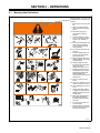
SECTION 3 − DEFINITIONS
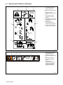
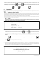
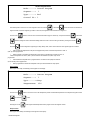
3-1. Warning Label Definitions
Warning! Watch Out! There are
possible hazards as shown by the
symbols.
1 Electric shock from wiring can
kill.
1.1 Wear dry insulating gloves.
Do not wear wet or damaged
gloves.
1.2 Disconnect input plug or
power before working on
machine.
2 Induction heating can cause
injury or burns from hot items
such as rings, watches, or
parts.
2.1 Do not wear metal jewelry and
other metal personal items
such as rings and watches
during operation.
2.2 Do not touch hot parts or hot
head/coil.
3 Induction heating sparks can
cause fire. Do not overheat
parts and adhesives.
3.1 Keep flammables away from
heating operation. Do not heat
near flammables.
3.2 Heating sparks can cause
fires. Have a fire extinguisher
nearby and have a
watchperson ready to use it.
4 Breathing heating fumes can
be hazardous to your health.
Read Material Safety Data
Sheets (MSDSs) and
manufacturer’s instructions for
material used.
4.1 Keep your head out of the
fumes.
4.2 Use forced ventilation or local
exhaust to remove the fumes.
4.3 Use ventilating fan to remove
fumes.
5 Always wear safety glasses
or goggles during and around
heating operations to prevent
possible injury.
5.1 Wear either safety glasses or
full goggles depending on
type of operation and nearby
processes.
6 Do not remove or paint over
(cover) the label.
7 Become trained and read the
instructions before working on
the machine or heating.
190 025

OM-222 166 Page 8
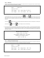
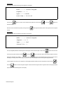
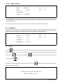
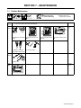
3-2. Warning Label Definitions (Continued)
1 Warning! Watch Out! There
are possible hazards as
shown by the symbols.
2 Electric shock from wiring can
kill.
3 Overuse can cause
overheating. Follow rated duty
cycle.
4 Disconnect input plug or
power before working on
machine.
5 Become trained and read the
instructions before working on
the machine.
6 Connect green or
green/yellow grounding
conductor to ground terminal.
7 Connect input conductors (L1,
L2 And L3) to line terminals.
194 466
12
4
5
3
6
7
227 085-A
123 4
1 Warning! Watch Out! There
are possible hazards as
shown by the symbols.
2 Electric shock from wiring can
kill.
3 Disconnect input plug or
power before working on
machine.
4 Do not touch input
capacitor(s). Allow time for
capacitor(s) to discharge.
Check input capacitor(s)
voltage (see Section 9-7).

OM-222 166 Page 9
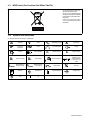
3-3. WEEE Label (For Products Sold Within The EU)
Do not discard product (where ap-
plicable) with general waste.
Reuse or recycle Waste Electrical
and Electronic Equipment (WEEE)
by disposing at a designated collec-
tion facility.
Contact your local recycling office
or your local distributor for further
information.
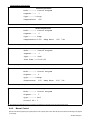
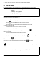
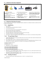
3-4. Symbols And Definitions
. Some symbols are found only on CE products.
A
Amperes
V
Volts Alternating Current
X
Duty Cycle
IP
Degree Of
Protection
Hz
Hertz Circuit Protection Output
Increase Line Connection
I
1
Primary Current
I
2
Rated Current
U
1
Primary Voltage
U
2
Load Voltage Read Instructions
Three Phase Static
Frequency Con-
verter-Transform-
er-Frequency Con-
verter
I
1max
Rated Maximum
Supply Current
P
1max
Maximum Power
Consumption
Three Phase Percent
Remote Panel/Local High Temperature Voltage Input
Off On

OM-222 166 Page 10
SECTION 4 − INSTALLATION
4-1. Serial Number and Rating Label Location
The serial number and rating information for the power source is located on the front of the machine. Use the rating labels to determine input power
requirements and/or rated output. For future reference, write serial number in space provided on back cover of this manual.
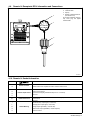
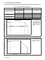
4-2. Specifications
Output
Frequen
cy
Rated Output
Required
Reflective
Inductance
Amperes Input at
Rated Load Output
50 or 60 Hz,
Three-Phase
Overall
Dimensions
Weight
IP
Rating
Single
Output
Dual
Output
400 V 460 V 575 V
kVA kW
5 To 30
kHz
35 kW At
100%
Duty
Cycle
350 A
(RMS),
700 V
(RMS)
35 kW At
100%
Duty
Cycle
700 A
(RMS),
700 V
(RMS)
2.5 To 50
μh
60 A 50 A 40 A 39 37
Length: 36-3/4 in
(993 mm)
Width: 21-1/2 in
(546 mm)
Height: 29 in
(737 mm)
227 lb
(103 kg)
23CM
Storage Temperature Range −40_ F (−40_ C) to 122_ F (50_ C)
*While idling
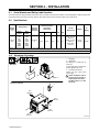
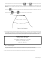
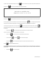
4-3. Selecting A Location
1 Lifting Eye
2 Lifting Forks
Use lifting eye or lifting forks to
move unit.
If using lifting forks, extend forks
beyond opposite side of unit.
3 Line Disconnect Device
Locate unit near correct input
power supply.
! Special installation may be
required where gasoline or
volatile liquids are present −
see NEC Article 511 or CEC
Section 20.
3
18 in
(460 mm)
18 in
(460 mm)
OR
1
2
Movement
Location And Airflow
803 992-B
12 in
(305 mm)
12 in
(305 mm)

OM-222 166 Page 11
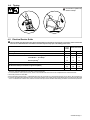
4-4. Tipping
! Do not move or operate unit
where it could tip.
4-5. Electrical Service Guide
Failure to follow these electrical service guide recommendations could create an electric shock or fire hazard. These recommenda-
tions are for a dedicated branch circuit sized for the rated output and duty cycle of the welding power source.
50 Hz
Three
Phase
60 Hz Three Phase
Input Voltage 400 460 575
Input Amperes At Rated Output 60 50 40
Max Recommended Standard Fuse Or Circuit Breaker Rating In Amperes
1
Circuit Breaker
1
, Time-Delay
2
70 61 45
Normal Operating
3
80 70 60
Min Input Conductor Size In AWG
4
6 8 8
Max Recommended Input Conductor Length In Feet (Meters)
254
(77)
214
(65)
334
(102)
Min Grounding Conductor Size In AWG
4
8 8 10
Reference: 2005 National Electrical Code (NEC) (including article 630)
1 If a circuit breaker is used in place of a fuse, choose a circuit breaker with time-current curves comparable to the recommended fuse.
2 Time-Delay fuses are UL class RK5 .
3 Normal Operating (general purpose - no intentional delay) fuses are UL class K5 (up to and including 60 amp), and UL class H ( 65 amp and above).
4 Conductor data in this section specifies conductor size (excluding flexible cord or cable) between the panelboard and the equipment per NEC Table
310.16. If a flexible cord or cable is used, minimum conductor size may increase. See NEC Table 400.5(A) for flexible cord and cable requirements.

OM-222 166 Page 12
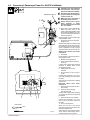
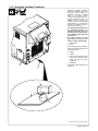
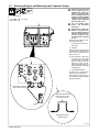
4-6. Connecting 3-Phase Input Power For 460/575 Volt Models
803 994-C
3/8 in
Tools Needed:
! Installation must meet all National
and Local Codes − have only quali-
fied persons make this installation.
! Disconnect and lockout/tagout in-
put power before connecting input
conductors from unit.
! Make input power connections to
the welding power source first.
! Always connect green or green/
yellow conductor to supply
grounding terminal first, and never
to a line terminal.
. The circuitry in this unit automatically
adapts the power source to the
primary voltage being applied. Check
input voltage available at site. This
unit can be connected to either 460 or
575 VAC input power.
See rating label on unit and check input
voltage available at site.
1 Input Power Conductors (Customer
Supplied Cord)
Select size and length of conductors using
Section NO TAG. Conductors must com-
ply with national, state, and local electrical
codes. If applicable, use lugs of proper
amperage capacity and correct hole size.
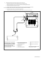
Welding Power Source Input Power
Connections
2 Strain Relief
Route conductors (cord) through strain re-
lief and tighten screws.
3 Machine Grounding Terminal
4 Green Or Green/Yellow Grounding
Conductor
Connect green or green/yellow grounding
conductor to welding power source
grounding terminal first.
5 Welding Power Source Line
Terminals
6 Input Conductors L1 (U), L2 (V) And
L3 (W)
Connect input conductors L1 (U), L2 (V)
and L3 (W) to welding power source line
terminals.
Close and secure access door on welding
power source.
Disconnect Device Input Power
Connections
7 Disconnect Device (switch shown in
OFF position)
8 Disconnect Device (Supply)
Grounding Terminal
Connect green or green/yellow grounding
conductor to disconnect device grounding
terminal first.
9 Disconnect Device Line Terminals
Connect input conductors L1 (U), L2 (V)
And L3 (W) to disconnect device line
terminals.
10 Over-Current Protection
Select type and size of over-current
protection using Section NO TAG (fused
disconnect switch shown).
Close and secure door on line disconnect
device. Remove lockout/tagout device,
and place switch in the On position.
GND/PE Earth Ground
7
2
10
8
4
9
1
6
3
4
3
6
5

OM-222 166 Page 13
Ref. 804 430-A
Tools Needed:
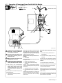
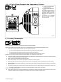
4-7. Connecting 3-Phase Input Power For 400/460 Volt Models
3/8 in
! Installation must meet all National and
Local Codes − have only qualified per-
sons make this installation.
! Disconnect and lockout/tagout input
power before connecting input con-
ductors from unit.
! Make input power connections to the
welding power source first.
! Always connect green or green/yellow
conductor to supply grounding termi-
nal first, and never to a line terminal.
. The circuitry in this unit automatically
adapts the power source to the primary
voltage being applied. Check input
voltage available at site. This unit can be
connected to either 400 or 460 VAC input
power.
See rating label on unit and check input volt-
age available at site.
1 Input Power Conductors (Customer
Supplied Cord)
Select size and length of conductors using
Section NO TAG. Conductors must comply
with national, state, and local electrical codes.
If applicable, use lugs of proper amperage
capacity and correct hole size.
Welding Power Source Input Power Con-
nections
2 Strain Relief
Route conductors (cord) through strain relief
and tighten screws.
3 Machine Grounding Terminal
4 Green Or Green/Yellow Grounding
Conductor
Connect green or green/yellow grounding
conductor to welding power source grounding
terminal first.
5 Welding Power Source Line Terminals
6 Input Conductors L1 (U), L2 (V) And L3
(W)
Connect input conductors L1 (U), L2 (V) and
L3 (W) to welding power source line terminals.
Close and secure access door on welding
power source.
Disconnect Device Input Power Connec-
tions
7 Disconnect Device (switch shown in
OFF position)
8 Disconnect Device (Supply) Grounding
Terminal
Connect green or green/yellow grounding
conductor to disconnect device grounding ter-
minal first.
9 Disconnect Device Line Terminals
Connect input conductors L1 (U), L2 (V) And
L3 (W) to disconnect device line terminals.
10 Over-Current Protection
Select type and size of over-current protection
using Section NO TAG (fused disconnect
switch shown).
Close and secure door on line disconnect de-
vice. Remove lockout/tagout device, and
place switch in the On position.
7
8
1
5
4
2
3
4
L1
L2
L3
6
9
10
= GND/PE Earth Ground
3
6

OM-222 166 Page 14
Ref. 803 993-C / Ref. 804 217-A
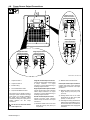
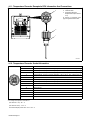
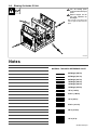
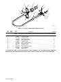
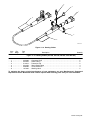
4-8. Power Source Output Connections
1 Output Connector 1
2 Output Connector 2
3 Protective Plug
4 Air-Cooled Extension Cable
5 Liquid-Cooled Extension Cable
The power source is capable of single or
dual output. When connected for single
power output, up to 35 kW is available at
the single output connection. When
connected for dual power, output power is
divided between the two output
connections.
! Do not move or disconnect cables
while output is on.
Single Air-Cooled Output Connection
Connect air-cooled output extension cable
to Output Connector 1 or Output
Connector 2. Connect Protective Plug to
remaining Output Connector.
Single Liquid-Cooled Output Connection
Connect liquid-cooled output extension
cable to Output Connector 1 or Output
Connector 2. Connect Protective Plug to
remaining Output Connector.
Dual Air-Cooled Output Connection
Connect air-cooled output extension
cables to Output Connector 1 and Output
Connector 2.
. Extension cables must be the same
length: 25 ft (7.6 m), 50 ft (15.2 m), or
75 ft (22.8 m).
. Blankets must be the same size.
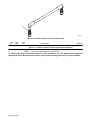
Dual Liquid-Cooled Output Connection
Connect liquid-cooled output extension
cables to Output Connector 1 and Output
Connector 2.
. Extension cables must be the same
length: 10 ft (3 m), 25 ft (7.6 m), or 50
ft (15.2 m).
. Heating cables must be the same
length: 30ft (9.1 m), 50 ft (15.2 m), 80ft
(24.2 m), or 140 ft (42.7 m).
. Total length of heating and extension
cables must not exceed 360 ft (110 m).
The extension cable is counted twice
the length because it has a supply and
return hose.
1
2
12
Single Air-Cooled
Output Connection
Dual Air-Cooled
Output Connection
Dual Liquid-Cooled
Output Connection
3
4
4
4
55
12
12
Single Liquid-Cooled
Output Connection
12
3
5
12
La page est en cours de chargement...
La page est en cours de chargement...
La page est en cours de chargement...
La page est en cours de chargement...
La page est en cours de chargement...
La page est en cours de chargement...
La page est en cours de chargement...
La page est en cours de chargement...
La page est en cours de chargement...
La page est en cours de chargement...
La page est en cours de chargement...
La page est en cours de chargement...
La page est en cours de chargement...
La page est en cours de chargement...
La page est en cours de chargement...
La page est en cours de chargement...
La page est en cours de chargement...
La page est en cours de chargement...
La page est en cours de chargement...
La page est en cours de chargement...
La page est en cours de chargement...
La page est en cours de chargement...
La page est en cours de chargement...
La page est en cours de chargement...
La page est en cours de chargement...
La page est en cours de chargement...
La page est en cours de chargement...
La page est en cours de chargement...
La page est en cours de chargement...
La page est en cours de chargement...
La page est en cours de chargement...
La page est en cours de chargement...
La page est en cours de chargement...
La page est en cours de chargement...
La page est en cours de chargement...
La page est en cours de chargement...
La page est en cours de chargement...
La page est en cours de chargement...
La page est en cours de chargement...
La page est en cours de chargement...
La page est en cours de chargement...
La page est en cours de chargement...
La page est en cours de chargement...
La page est en cours de chargement...
La page est en cours de chargement...
La page est en cours de chargement...
La page est en cours de chargement...
La page est en cours de chargement...
La page est en cours de chargement...
La page est en cours de chargement...
La page est en cours de chargement...
La page est en cours de chargement...
La page est en cours de chargement...
La page est en cours de chargement...
La page est en cours de chargement...
La page est en cours de chargement...
La page est en cours de chargement...
La page est en cours de chargement...
-
 1
1
-
 2
2
-
 3
3
-
 4
4
-
 5
5
-
 6
6
-
 7
7
-
 8
8
-
 9
9
-
 10
10
-
 11
11
-
 12
12
-
 13
13
-
 14
14
-
 15
15
-
 16
16
-
 17
17
-
 18
18
-
 19
19
-
 20
20
-
 21
21
-
 22
22
-
 23
23
-
 24
24
-
 25
25
-
 26
26
-
 27
27
-
 28
28
-
 29
29
-
 30
30
-
 31
31
-
 32
32
-
 33
33
-
 34
34
-
 35
35
-
 36
36
-
 37
37
-
 38
38
-
 39
39
-
 40
40
-
 41
41
-
 42
42
-
 43
43
-
 44
44
-
 45
45
-
 46
46
-
 47
47
-
 48
48
-
 49
49
-
 50
50
-
 51
51
-
 52
52
-
 53
53
-
 54
54
-
 55
55
-
 56
56
-
 57
57
-
 58
58
-
 59
59
-
 60
60
-
 61
61
-
 62
62
-
 63
63
-
 64
64
-
 65
65
-
 66
66
-
 67
67
-
 68
68
-
 69
69
-
 70
70
-
 71
71
-
 72
72
-
 73
73
-
 74
74
-
 75
75
-
 76
76
-
 77
77
-
 78
78


Miller LJ470011G Le manuel du propriétaire
- Catégorie
- Système de soudage
- Taper
- Le manuel du propriétaire
- Ce manuel convient également à
dans d''autres langues
- English: Miller LJ470011G Owner's manual
Documents connexes
-
Miller PROHEAT 35 CE 907271, 907298, 907432 Le manuel du propriétaire
-
-
Miller LG015710 Le manuel du propriétaire
-
-
-
-
Miller PROHEAT 35 907689, 907690 Le manuel du propriétaire
-
Miller PROHEAT HEAVY DUTY INDUCTION COOLER (48 VOLT) Le manuel du propriétaire
-
-