Klein Tools VDV501-097 Mode d'emploi
- Catégorie
- Mesure, test
- Taper
- Mode d'emploi

ENGLISH
Español pg. 11
Português pg. 21
Français pg. 31
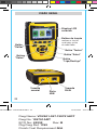
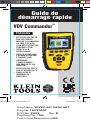
VDV Commander
TM
• TESTS CABLES
• MEASURES
CABLE LENGTH
WITH TDR
• DETECTS FAULTS
• DETECTS AND
MEASURES PoE
• LOCATES AND
IDENTIFIES CABLES
• TESTS ACTIVE NETWORK
• SAVE AND PRINT REPORTS
Quick Start Guide
Dwg Name: VDV501-097-139791ART
Dwg No: 139791ART
ECO No: 42232 Rev: B
Pkg Dwg Ref: 1762
Finish Coat Requirement:N/A
VDV501-097-139791ART.indd 1VDV501-097-139791ART.indd 1 11/16/2021 9:15:55 AM11/16/2021 9:15:55 AM

2
Dwg Name: VDV501-097-139791ART
Dwg No: 139791ART
ECO No: 42232 Rev: B
Pkg Dwg Ref: 1762
Finish Coat Requirement:N/A
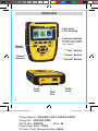
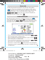
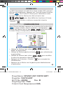
OVERVIEW
USB
Port
RJ45
Jack
Coax
Jack
Full-color
LCD Display
Function Buttons
perform the function
on the display above
each button
"Arrow"
Buttons
"Test" Button
"Enter" Button
"On/Off" Button
"Back"
Button
VDV501-097-139791ART.indd 2VDV501-097-139791ART.indd 2 11/16/2021 9:15:58 AM11/16/2021 9:15:58 AM

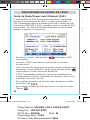
The VDV Commander features a full-color graphic LCD screen.
Press any of the four blue buttons below the on-screen
icon to select that function. Alternately, you can use the side or
up/down arrows to scroll to desired
on-screen function and press the "Enter" button .
LCD SCREEN
From the main screen, press the blue function button
on the far right below the “setup” symbol . Use the
up and down arrow buttons to scroll through
the Setup menu and to select an option.
SETUP
• Use the up and down arrow buttons
to
navigate through the settings.
• Use the left and right arrow buttons
to select setting.
• Use the up and down arrow buttons
to change
the selected setting.
• Press the "Enter" button to accept your changes.
• Press the left arrow to unselect a setting.
3
Dwg Name: VDV501-097-139791ART
Dwg No: 139791ART
ECO No: 42232 Rev: B
Pkg Dwg Ref: 1762
Finish Coat Requirement:N/A
VDV501-097-139791ART.indd 3VDV501-097-139791ART.indd 3 11/16/2021 9:16:01 AM11/16/2021 9:16:01 AM

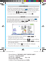
GENERAL TESTING PROCEDURES
Performing a Cable Test
Press the "On/Off" button to power on the
VDV Commander.
• Connect a network, coax, or telephone cable to the
appropriate connector on the top of the VDV Commander.
WARNING: Do NOT plug an RJ12 cable directly into the VDV
Commander. A standard RJ12 cable will damage the VDV
Commander’s RJ45 jack. Use the RJ adapter patch cable
(VDV726-125) that is included with the VDV Commander.
• Press the "Enter" button to display the cable test
menu. The VDV Commander will automatically perform a
test upon entering the cable test menu.
• To scroll through Cable Type mode, press the RJ45
function button. The icon will change with each press, from
RJ45 to coax to telephone / / .
• If a Test-n-Map
TM
remote is NOT being used (a one ended
test), the VDV Commander will test the length of each pair,
open, short, or split pair. Performing a one ended test will not
verify connectivity on the opposite end of the cable.
• If a remote is being used, connect the remote to the opposite
end of the cable.
• To calibrate the VoP, connect a known length of cable to the
VDV Commander and press the up/down/left/right buttons to
increase or decrease the VoP. Press the left and right buttons
to select and change the VoP one digit at a time.
• While adjusting the VoP, press the test button until the desired
length of the cable is displayed.
• To save the calibrated VoP, enter the settings menu and press
the "Save" function button .
NOTE: your adjusted VoP will be displayed next to the
RJ45 or coax icon.
• Press the green test button or the loop mode
function button to perform additional tests.
GENERAL TESTING PROCEDURES
4
Dwg Name: VDV501-097-139791ART
Dwg No: 139791ART
ECO No: 42232 Rev: B
Pkg Dwg Ref: 1762
Finish Coat Requirement:N/A
VDV501-097-139791ART.indd 4VDV501-097-139791ART.indd 4 11/16/2021 9:16:05 AM11/16/2021 9:16:05 AM

Saving a Test File
• To save a cable test, press the "Save" function button .
• Use the arrow buttons and
the "Enter" button to name the cable test file.
• Press the "Save" function button to save the cable
test file.
GENERAL TESTING PROCEDURES
5
Dwg Name: VDV501-097-139791ART
Dwg No: 139791ART
ECO No: 42232 Rev: B
Pkg Dwg Ref: 1762
Finish Coat Requirement:N/A
VDV501-097-139791ART.indd 5VDV501-097-139791ART.indd 5 11/16/2021 9:16:05 AM11/16/2021 9:16:05 AM

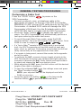
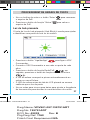
GENERAL TESTING PROCEDURES
Hub Blink
The Hub Blink test is used to help identify a hub or switch port.
• Press the "On/Off" button to power on the
VDV Commander.
• Connect the VDV Commander to an active network cable or port.
• Press the Network/PoE function button , then
press the Link Light function button .
• The Link Light will automatically begin to blink upon
entering the Link menu.
• The Link LED above the LCD screen will flash at the same
cadence as the port light.
• Use the up and down arrows to adjust the transmit
frequency to suit the switch characteristics.
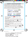
• Press the "On/Off" button to power on the
VDV Commander.
• Connect the VDV Commander to a switch or active
network jack.
• Use the left or right arrow buttons to select the Network/
PoE icon and press the "Enter" button or press the
Network/POE function button.
• The VDV Commander will automatically detect and
display link capability, connection speed, PoE class,
and PoE Min/Max voltages.
• To perform a network test only, press the PoE function
button .
• To save the PoE data, press the "Save" function button
.
• Use the arrow buttons and the "Enter" button to name
the PoE file.
• Press the "Save" function button to save the PoE file.
GENERAL TESTING PROCEDURES
Network/Power over Ethernet PoE Testing
The VDV Commander PoE test identifies the link capability of
a network drop and the connection status. VDV Commander
detects the presence of PoE, PoE class per IEEE 802.3 af/at,
and also measures PoE voltages under load. The Network/PoE
tests can be saved for record keeping and printing.
6
Dwg Name: VDV501-097-139791ART
Dwg No: 139791ART
ECO No: 42232 Rev: B
Pkg Dwg Ref: 1762
Finish Coat Requirement:N/A
VDV501-097-139791ART.indd 6VDV501-097-139791ART.indd 6 11/16/2021 9:16:11 AM11/16/2021 9:16:11 AM

GENERAL TESTING PROCEDURES
Hub Blink
The Hub Blink test is used to help identify a hub or switch port.
• Press the "On/Off" button to power on the
VDV Commander.
• Connect the VDV Commander to an active network cable or port.
• Press the Network/PoE function button , then
press the Link Light function button .
• The Link Light will automatically begin to blink upon
entering the Link menu.
• The Link LED above the LCD screen will flash at the same
cadence as the port light.
• Use the up and down arrows to adjust the transmit
frequency to suit the switch characteristics.
• Press the "On/Off" button to power on the
VDV Commander.
• Connect the VDV Commander to a switch or active
network jack.
• Use the left or right arrow buttons to select the Network/
PoE icon and press the "Enter" button or press the
Network/POE function button.
• The VDV Commander will automatically detect and
display link capability, connection speed, PoE class,
and PoE Min/Max voltages.
• To perform a network test only, press the PoE function
button .
• To save the PoE data, press the "Save" function button
.
• Use the arrow buttons and the "Enter" button to name
the PoE file.
• Press the "Save" function button to save the PoE file.
Network/Power over Ethernet PoE Testing
The VDV Commander PoE test identifies the link capability of
a network drop and the connection status. VDV Commander
detects the presence of PoE, PoE class per IEEE 802.3 af/at,
and also measures PoE voltages under load. The Network/PoE
tests can be saved for record keeping and printing.
7
Dwg Name: VDV501-097-139791ART
Dwg No: 139791ART
ECO No: 42232 Rev: B
Pkg Dwg Ref: 1762
Finish Coat Requirement:N/A
VDV501-097-139791ART.indd 7VDV501-097-139791ART.indd 7 11/16/2021 9:16:11 AM11/16/2021 9:16:11 AM

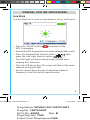
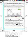
GENERAL TESTING PROCEDURES
• Press the "On/Off" button to power on the
VDV Commander.
• Use the left and right arrow buttons to select the
tone generator icon and press the "Enter" button .
• The VDV Commander will automatically activate the tone
generator upon entering the tone generator menu.
• Connect your cable to either the RJ45 jack or coax
connector located on the top of the VDV Commander.
• To switch between network and coax cables, press the
coax cable / RJ45 function button / .
• Use the up and down arrow buttons to select
tone cadences 1 through 4.
• Use the left and right arrow buttons to select which
pin or pair to place the tone.
• Use a tone tracing probe* (PROBEplus VDV500-123) alongside
the cable or at the end of the cable to hear an audible tone.
Tone Generator
Tone generation is used to trace cable runs and locate faults by sound.
This mode emits a cadence from the VDV Commander through the
connected cable. The tone is detected by a tone tracing probe*.
*
Probe is included in some kits.
8
Dwg Name: VDV501-097-139791ART
Dwg No: 139791ART
ECO No: 42232 Rev: B
Pkg Dwg Ref: 1762
Finish Coat Requirement:N/A
VDV501-097-139791ART.indd 8VDV501-097-139791ART.indd 8 11/16/2021 9:16:11 AM11/16/2021 9:16:11 AM

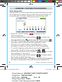
The VDV Commander application gives you the ability to
view, save and print cable and network test results on
your computer. This application can also update your VDV
Commander’s firmware.
To install the VDV Commander App
• Go to the VDV Commander product page on
www.kleintools.com to download the
VDV Commander software application.
• Save the VDV Commander Application file to your
computer’s desktop. Double click on the file to open it.
• Double-click on “SET-UP.exe” to begin installation.
VDV COMMANDER APP
9
Dwg Name: VDV501-097-139791ART
Dwg No: 139791ART
ECO No: 42232 Rev: B
Pkg Dwg Ref: 1762
Finish Coat Requirement:N/A
VDV501-097-139791ART.indd 9VDV501-097-139791ART.indd 9 11/16/2021 9:16:11 AM11/16/2021 9:16:11 AM

KLEIN TOOLS, INC.
450 Bond Street
Lincolnshire, IL 60069
www.kleintools.com
CUSTOMER SERVICE
WARNINGS
To ensure safe operation and service of the tester, follow
instructions. Failure to observe these warnings can result in
severe injury or death.
The VDV Commander is designed for use on cabling systems
with or without voltage.
• The voltage icon turns on when the voltage exceeds Safety
Extra Low Voltage (SELV) rating of 60 Volts peak AC or DC.
• It is NOT recommended to use the VDV Commander when
the voltage icon is present. Operating the VDV Commander
when a voltage source exceeds 60 Volts peak AC or DC may pose
a safety hazard for the user.
• Internal components are protected up to 400 Volts peak AC or DC.
• Always wear approved eye protection.
SYMBOLS:
Warning or
caution.
Risk of electrical shock.
Read instruccions
Conformité Européenne. Conforms with European Economic
Area directives.
UKCA - United Kingdom Conformity Assessment
This symbol indicates that equipment and its accessories
shall be subject to a separate collection and correct disposal.
10
Dwg Name: VDV501-097-139791ART
Dwg No: 139791ART
ECO No: 42232 Rev: B
Pkg Dwg Ref: 1762
Finish Coat Requirement:N/A
VDV501-097-139791ART.indd 10VDV501-097-139791ART.indd 10 11/16/2021 9:16:14 AM11/16/2021 9:16:14 AM

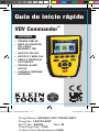
ESPAÑOL
VDV Commander
TM
• PRUEBA CABLES
• MIDE LA LONGITUD
DEL CABLE
MEDIANTE TDR
• DETECTA FALLAS
• DETECTA Y MIDE PoE
• UBICA E IDENTIFICA
LOS CABLES
• PRUEBA LA RED
ACTIVA
• GUARDA E IMPRIME
INFORMES
Dwg Name: VDV501-097-139791ART
Dwg No: 139791ART
ECO No: 42232 Rev: B
Pkg Dwg Ref: 1762
Finish Coat Requirement:N/A
Guía de inicio rápido
VDV501-097-139791ART.indd 11VDV501-097-139791ART.indd 11 11/16/2021 9:16:20 AM11/16/2021 9:16:20 AM

12
Dwg Name: VDV501-097-139791ART
Dwg No: 139791ART
ECO No: 42232 Rev: B
Pkg Dwg Ref: 1762
Finish Coat Requirement:N/A
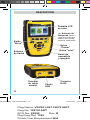
DESCRIPCIÓN
Puerto
USB
Conector
RJ45
Conector
de cable
coaxial
Pantalla LCD
en color
Los
botones de
funciones
llevan a
cabo la función que
aparece en pantalla,
arriba de cada botón
Botones
de echa
Botón
"Probar"
Botón "Intro"
Botón de
encendido
yapagado
Botón
"Atrás"
VDV501-097-139791ART.indd 12VDV501-097-139791ART.indd 12 11/16/2021 9:16:23 AM11/16/2021 9:16:23 AM

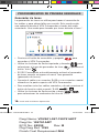
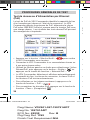
El VDVCommander cuenta con una pantalla LCD en color.
Presione cualquiera de los cuatro botones azules
debajodel icono de pantalla para seleccionar esa función.
También puede utilizar las flechas laterales o arriba/abajo
para desplazarse hacia la función
de pantalla deseada y presionar el botón "Intro" .
PANTALLA LCD
CONFIGURACIÓN
• Utilice los botones de flecha arriba y abajo
paradesplazarse por los ajustes.
• Utilice los botones de flecha derecha e izquierda
paraseleccionar el ajuste.
• Utilice los botones de flecha arriba y abajo
paramodificar el ajuste seleccionado.
• Presione el botón "Intro" para aceptar los cambios.
• Presione la flecha izquierda para anular la selección de
unajuste.
En la pantalla principal, presione el botón de función azul
a la derecha, debajo del símbolo de configuración .
Utilice los botones de flecha arriba y abajo para
desplazarse por el menú Setup (Configuración) y seleccionar
una opción.
13
Dwg Name: VDV501-097-139791ART
Dwg No: 139791ART
ECO No: 42232 Rev: B
Pkg Dwg Ref: 1762
Finish Coat Requirement:N/A
VDV501-097-139791ART.indd 13VDV501-097-139791ART.indd 13 11/16/2021 9:16:25 AM11/16/2021 9:16:25 AM

PROCEDIMIENTOS DE PRUEBAS GENERALES
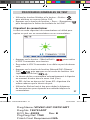
Prueba de cables
Presione el botón de encendido y apagado para
encender el VDVCommander.
• Conecte un cable telefónico, coaxial o de red al conector
apropiado en la parte superior del VDV Commander.
ADVERTENCIA: NO conecte un cable RJ12 directamente
al VDV Commander. Un cable RJ12 estándar dañará el
conector RJ45 del VDV Commander. Utilice el cable de
empalme del adaptador RJ (VDV726-125) que viene con
elVDV Commander.
• Presione el botón "Intro" para visualizar el menú
de prueba de cables. El VDV Commander realizará una
pruebaautomáticamente cuando se ingrese al menú de
prueba de cables.
• Para desplazarse por el modo Cable Type (Tipo de cable),
presione el botón de función RJ45. El icono cambiará
cadavez que lo presiona, de RJ45 a coaxial y a teléfono
/ / .
• Si NO se utiliza un transmisor remoto Test-n-MapTM
(pruebaen un solo extremo), el VDVCommander probará
lalongitud de cada par, del par abierto, en corto o dividido.
La realización de prueba en un solo extremo no verificará
laconexión en el extremo opuesto del cable.
• Si se utiliza un transmisor remoto, conéctelo al extremo
opuesto del cable.
• Para calibrar la VoP, conecte una longitud conocida de
cableal VDV Commander y presione los botones arriba/
abajo/izquierda/derecha para aumentar o disminuir el VoP
Presione los botones izquierda y derecha para seleccionar
ymodificar la VoP, de a un dígito por vez.
• Al ajustar la VoP, presione el botón de prueba hasta que
aparezca la longitud de cable deseada.
PROCEDIMIENTOS DE PRUEBAS GENERALES
14
Dwg Name: VDV501-097-139791ART
Dwg No: 139791ART
ECO No: 42232 Rev: B
Pkg Dwg Ref: 1762
Finish Coat Requirement:N/A
VDV501-097-139791ART.indd 14VDV501-097-139791ART.indd 14 11/16/2021 9:16:27 AM11/16/2021 9:16:27 AM

• Para guardar la VoP, ingrese al menú de ajustes y presione
el botón de función "Guardar" .
NOTA: la VoP ajustada aparecerá junto al icono
coaxial o RJ45.
• Presione el botón de prueba verde o el botón
de función del modo bucle para realizar pruebas
adicionales.
Guardado de un archivo de prueba
• Para guardar una prueba de cables, presione el botón
defunción "Guardar" .
• Utilice los botones de flecha y
el botón "Intro" para asignarle un nombre al archivo
deprueba de cables.
• Presione el botón de función "Guardar" para guardar
elarchivo de prueba de cables.
PROCEDIMIENTOS DE PRUEBAS GENERALES
15
Dwg Name: VDV501-097-139791ART
Dwg No: 139791ART
ECO No: 42232 Rev: B
Pkg Dwg Ref: 1762
Finish Coat Requirement:N/A
VDV501-097-139791ART.indd 15VDV501-097-139791ART.indd 15 11/16/2021 9:16:29 AM11/16/2021 9:16:29 AM

PROCEDIMIENTOS DE PRUEBAS GENERALES
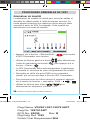
Parpadeo del concentrador
La prueba de parpadeo del concentrador se utiliza para ayudar
a identificar un puerto de conmutación o concentrador.
• Presione el botón de encendido y apagado para
encender el VDV Commander.
• Conecte el VDV Commander a un puerto o cable de red
activo.
• Presione el botón de función Red/PoE . A
continuación, presione el botón de función Indicador de
enlace .
• El Indicador de enlace comenzará a parpadear
automáticamente cuando se ingrese al menú Link (Enlace).
• El LED indicador sobre la pantalla LCD parpadeará con la
misma cadencia que la luz del puerto.
• Utilice las flechas arriba y abajo para ajustar la frecuencia
detransmisión y adaptarla a las características del
conmutador.
• Presione el botón de encendido y apagado para
encender el VDVCommander.
• Conecte el VDVCommander a un interruptor o a un conector
de red activa.
• Utilice los botones de flecha izquierda o derecha para
seleccionar el icono de Red/PoE y presione el botón "Intro"
o el botón de función Network/PoE.
• El VDVCommander automáticamente detectará y mostrará
la capacidad de enlace, la velocidad de conexión, la clase de
PoE y los voltajes mín./máx. de PoE.
• Para realizar una prueba de red solamente, presione el botón
de función PoE .
• Para guardar los datos de PoE, presione el botón de función
"Guardar" .
• Utilice los botones de flecha y el botón "Intro" para
asignarle un nombre al archivo de PoE.
• Presione el botón de función "Guardar" para guardar el
archivo de PoE.
PROCEDIMIENTOS DE PRUEBAS GENERALES
Prueba de red/PoE
La prueba de PoE del VDV Commander identifica la capacidad
de enlace de una conexión de red y el estado de la conexión.
El VDV Commander detecta la presencia de PoE, clase de PoE
según la norma IEEE 802.3 af/at y también mide los voltajes de
PoE con carga. Las pruebas de Red/PoE se pueden guardar
para mantener un registro e imprimirlas.
16
Dwg Name: VDV501-097-139791ART
Dwg No: 139791ART
ECO No: 42232 Rev: B
Pkg Dwg Ref: 1762
Finish Coat Requirement:N/A
VDV501-097-139791ART.indd 16VDV501-097-139791ART.indd 16 11/16/2021 9:16:35 AM11/16/2021 9:16:35 AM

PROCEDIMIENTOS DE PRUEBAS GENERALES
Parpadeo del concentrador
La prueba de parpadeo del concentrador se utiliza para ayudar
a identificar un puerto de conmutación o concentrador.
• Presione el botón de encendido y apagado para
encender el VDV Commander.
• Conecte el VDV Commander a un puerto o cable de red
activo.
• Presione el botón de función Red/PoE . A
continuación, presione el botón de función Indicador de
enlace .
• El Indicador de enlace comenzará a parpadear
automáticamente cuando se ingrese al menú Link (Enlace).
• El LED indicador sobre la pantalla LCD parpadeará con la
misma cadencia que la luz del puerto.
• Utilice las flechas arriba y abajo para ajustar la frecuencia
detransmisión y adaptarla a las características del
conmutador.
• Presione el botón de encendido y apagado para
encender el VDVCommander.
• Conecte el VDVCommander a un interruptor o a un conector
de red activa.
• Utilice los botones de flecha izquierda o derecha para
seleccionar el icono de Red/PoE y presione el botón "Intro"
o el botón de función Network/PoE.
• El VDVCommander automáticamente detectará y mostrará
la capacidad de enlace, la velocidad de conexión, la clase de
PoE y los voltajes mín./máx. de PoE.
• Para realizar una prueba de red solamente, presione el botón
de función PoE .
• Para guardar los datos de PoE, presione el botón de función
"Guardar" .
• Utilice los botones de flecha y el botón "Intro" para
asignarle un nombre al archivo de PoE.
• Presione el botón de función "Guardar" para guardar el
archivo de PoE.
Prueba de red/PoE
La prueba de PoE del VDV Commander identifica la capacidad
de enlace de una conexión de red y el estado de la conexión.
El VDV Commander detecta la presencia de PoE, clase de PoE
según la norma IEEE 802.3 af/at y también mide los voltajes de
PoE con carga. Las pruebas de Red/PoE se pueden guardar
para mantener un registro e imprimirlas.
17
Dwg Name: VDV501-097-139791ART
Dwg No: 139791ART
ECO No: 42232 Rev: B
Pkg Dwg Ref: 1762
Finish Coat Requirement:N/A
VDV501-097-139791ART.indd 17VDV501-097-139791ART.indd 17 11/16/2021 9:16:35 AM11/16/2021 9:16:35 AM

PROCEDIMIENTOS DE PRUEBAS GENERALES
• Presione el botón de encendido y apagado para
encender el VDVCommander.
• Utilice los botones de flecha izquierda y derecha para
seleccionar el icono de generador de tono y presione el
botón "Intro" .
• El VDV Commander automáticamente activará el generador
de tonos cuando se ingrese al menú Tone generator
(generador
de tonos).
• Conecte el cable a un conector RJ45 o a un conector coaxial
ubicado en la parte superior del VDV Commander.
• Para cambiar entre los cables coaxiales y de red, presione el
botón de función cable coaxial / RJ45 / .
• Utilice los botones de flecha arriba y abajo
para seleccionar las cadencias de tono de 1 a 4.
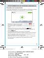
Generador de tonos
La generación de tonos se utiliza para trazar el recorrido de
los cables y para ubicar fallas por sonido. Este modo emite
una cadencia desde el VDVCommander a través del cable
conectado. Una sonda para trazado por tonos detecta el tono*.
*
La sonda está incluida en algunos kits.
18
Dwg Name: VDV501-097-139791ART
Dwg No: 139791ART
ECO No: 42232 Rev: B
Pkg Dwg Ref: 1762
Finish Coat Requirement:N/A
VDV501-097-139791ART.indd 18VDV501-097-139791ART.indd 18 11/16/2021 9:16:35 AM11/16/2021 9:16:35 AM

• Utilice los botones de flecha izquierda y derecha
p
araseleccionar en qué par o patilla ubicar el tono.
• Utilice una sonda para trazado por tonos* (
PROBEplus
VDV500-123
) junto al cable o al final del cable para
escucharun tono audible.
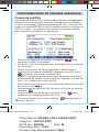
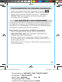
APLICACIÓN DEL VDVCOMMANDER
La aplicación del VDVCommander le brinda la posibilidad de
ver, guardar e imprimir los resultados de la prueba de red y
de cables en su computadora. Esta aplicación también puede
actualizar el firmware del VDV Commander.
Para instalar la aplicación del VDV Commander
• Vaya a la página del producto VDVCommander en
www.kleintools.com para descargar la aplicación de
software del VDVCommander.
• Guarde el archivo de la aplicación del VDVCommander
en elescritorio de su computadora. Haga doble clic en el
archivo para abrirlo.
• Haga doble clic en el archivo “SET-UP.exe” para comenzar
con la instalación.
PROCEDIMIENTOS DE PRUEBAS GENERALES
19
Dwg Name: VDV501-097-139791ART
Dwg No: 139791ART
ECO No: 42232 Rev: B
Pkg Dwg Ref: 1762
Finish Coat Requirement:N/A
VDV501-097-139791ART.indd 19VDV501-097-139791ART.indd 19 11/16/2021 9:16:35 AM11/16/2021 9:16:35 AM

KLEIN TOOLS, INC.
450 Bond Street
Lincolnshire, IL 60069, EE. UU.
www.kleintools.com
SERVICIO AL CLIENTE
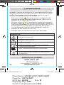
ADVERTENCIAS
Para garantizar un funcionamiento y un servicio seguros del
probador, siga las instrucciones. El incumplimiento de estas
advertencias puede dar lugar a lesiones o provocar la muerte.
El VDVCommander está diseñado para que se lo use en
sistemas de cableado con o sin voltaje.
• Este icono voltaje se activa cuando se supera el valor
nominal de voltaje extra bajo de protección (SELV) de un
máximo de 60voltios de CA o CD.
• NO debe utilizar el VDVCommander cuando esté presente
el icono voltaje . El uso del VDVCommander cuando la
fuente de voltaje supera el máximo de 60voltios de CA o CD
puede implicar un riesgo para la seguridad del usuario.
• Los componentes internos están protegidos hasta un
máximo de 400voltios de CA o CD.
• Siempre debe usar protección para ojos aprobada.
SÍMBOLOS:
Advertencia o precaución.
Riesgo de choque eléctrico.
Lea las instrucciones
Conformité Européenne. Cumple con las normas del
Espacio Económico Europeo.
UKCA - Conformidad evaluada por el Reino Unido
Este símbolo indica que el equipo y sus accesorios
son de recolección por separado y se deben desechar
correctamente.
20
Dwg Name: VDV501-097-139791ART
Dwg No: 139791ART
ECO No: 42232 Rev: B
Pkg Dwg Ref: 1762
Finish Coat Requirement:N/A
VDV501-097-139791ART.indd 20VDV501-097-139791ART.indd 20 11/16/2021 9:16:38 AM11/16/2021 9:16:38 AM
La page charge ...
La page charge ...
La page charge ...
La page charge ...
La page charge ...
La page charge ...
La page charge ...
La page charge ...
La page charge ...
La page charge ...
La page charge ...
La page charge ...
La page charge ...
La page charge ...
La page charge ...
La page charge ...
La page charge ...
La page charge ...
La page charge ...
La page charge ...
-
 1
1
-
 2
2
-
 3
3
-
 4
4
-
 5
5
-
 6
6
-
 7
7
-
 8
8
-
 9
9
-
 10
10
-
 11
11
-
 12
12
-
 13
13
-
 14
14
-
 15
15
-
 16
16
-
 17
17
-
 18
18
-
 19
19
-
 20
20
-
 21
21
-
 22
22
-
 23
23
-
 24
24
-
 25
25
-
 26
26
-
 27
27
-
 28
28
-
 29
29
-
 30
30
-
 31
31
-
 32
32
-
 33
33
-
 34
34
-
 35
35
-
 36
36
-
 37
37
-
 38
38
-
 39
39
-
 40
40


Klein Tools VDV501-097 Mode d'emploi
- Catégorie
- Mesure, test
- Taper
- Mode d'emploi
dans d''autres langues
- español: Klein Tools VDV501-097 Guía del usuario
- português: Klein Tools VDV501-097 Guia de usuario
Documents connexes
-
Klein Tools VDV Commander VDV501-097 Mode d'emploi
-
-
Klein Tools VDV770-850 Manuel utilisateur
-
Klein Tools VDV770-850 Manuel utilisateur
-
-
Klein Tools VDV501-826 Mode d'emploi
-
-
Klein Tools VDV501-826 Manuel utilisateur
-
Klein Tools VDV226-110 Manuel utilisateur