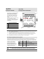
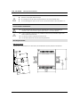
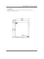
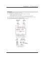
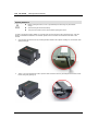
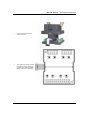
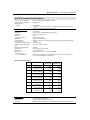
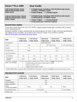
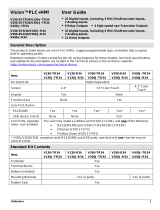
Vous trouverez ci-dessous de brèves informations pour Module d'extension E/S IO-ATC8. Ce module d'extension offre 8 entrées qui peuvent être configurées comme entrées analogiques ou thermocouples via le câblage, les cavaliers et les paramètres logiciels. Il se connecte aux contrôleurs OPLC Unitronics par un adaptateur. Le module peut être monté sur un rail DIN ou vissé sur une plaque de montage. Il dispose également d'indicateurs d'état et de points de connexion pour les entrées.
Vous trouverez ci-dessous de brèves informations pour Module d'extension E/S IO-ATC8. Ce module d'extension offre 8 entrées qui peuvent être configurées comme entrées analogiques ou thermocouples via le câblage, les cavaliers et les paramètres logiciels. Il se connecte aux contrôleurs OPLC Unitronics par un adaptateur. Le module peut être monté sur un rail DIN ou vissé sur une plaque de montage. Il dispose également d'indicateurs d'état et de points de connexion pour les entrées.


-
 1
1
-
 2
2
-
 3
3
-
 4
4
-
 5
5
-
 6
6
-
 7
7
-
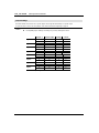 8
8
-
 9
9
-
 10
10
-
 11
11
-
 12
12
-
 13
13


Vous trouverez ci-dessous de brèves informations pour Module d'extension E/S IO-ATC8. Ce module d'extension offre 8 entrées qui peuvent être configurées comme entrées analogiques ou thermocouples via le câblage, les cavaliers et les paramètres logiciels. Il se connecte aux contrôleurs OPLC Unitronics par un adaptateur. Le module peut être monté sur un rail DIN ou vissé sur une plaque de montage. Il dispose également d'indicateurs d'état et de points de connexion pour les entrées.
dans d''autres langues
- English: Unitronics IO-ATC8 User manual
Documents connexes
-
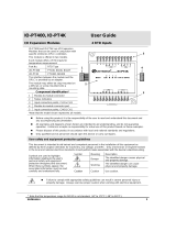 Unitronics IO-PT400 I-O Expansion Modules Mode d'emploi
-
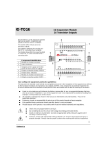 Unitronics IO-TO16 I/O Expansion Module Manuel utilisateur
-
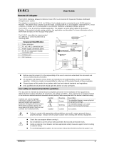 Unitronics EX-RC1 Remote I/O Adapter Mode d'emploi
-
 Unitronics Vision PLC+HMI Programmable Logic Controller Manuel utilisateur
-
Unitronics V530-53-B20B Mode d'emploi
-
Unitronics V1210-T20BJ Mode d'emploi
-
 Unitronics V130-33-TR34 Rugged Programmable Logic Controllers Mode d'emploi
-
Unitronics JZ20-R31 HMI Display Unit Mode d'emploi
-
 Unitronics V120-22-R34 Display units and HMIs Mode d'emploi


