Unitronics IO-TO16 I/O Expansion Module Manuel utilisateur
- Taper
- Manuel utilisateur

Unitronics
1
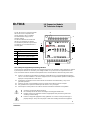
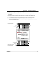
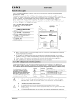
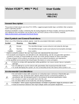
The IO-TO16 is an I/O expansion module 3
that can be used in conjunction with
specific Unitronics OPLC controllers.
The module offers 16 pnp (source)
transistor outputs.
The interface between the module and
the OPLC is provided by an adapter.
The module may either be snap-mounted
on a DIN rail, or screw-mounted onto a
mounting plate.
Component identification
3
User safety and equipment protection guidelines
This document is intended to aid trained and competent personnel in the installation of this equipment as defined
by the European directives for machinery, low voltage and EMC. Only a technician or engineer trained in the
local and national electrical standards should perform tasks associated with the electrical wiring of this device.
■
Under no circumstances will Unitronics be liable or responsible for any consequential damage that may
arise as a result of installation or use of this equipment, and is not responsible for problems resulting from
improper or irresponsible use of this device.
■
All examples and diagrams shown in the manual are intended to aid understanding. They do not
guarantee operation.
■
Unitronics accepts no responsibility for actual use of this product based on these examples.
■
Only qualified service personnel should open this device or carry out repairs.
■
Please dispose of this product in accordance with local and national standards and regulations.
■
Check the user program before running it.
■
Do not attempt to use this device with voltage exceeding permissible levels.
■
Install an external circuit breaker and take all appropriate safety measures against short-
circuiting in external wiring.
■
Failure to comply with appropriate safety guidelines can result in severe personal injury or
property damage. Always exercise proper caution when working with electrical equipment.
IO-TO16 I/O Expansion Module
16 Transistor Outputs
7
1
6
2
5
4
1
Module-to-module connector
2
Status indicators
3
Outputs’ power supply connection
points for each group of outputs
4
Output connection points: O8-O15
5
Output status indicators
6
Module-to-module connector port
7
Output connection points: O0-O7

2
Unitronics
IO- TO 16
I/O Expansion M odule
Mounting Considerations ■ Do not install in areas with: excessive or conductive dust, corrosive or
flammable gas, moisture or rain, excessive heat, regular impact
shocks or excessive vibration.
■
Provide proper ventilation by leaving a minimum space of 10mm
between the top and bottom edges of the device and the enclosure
walls.
■
Do not place in water or let water leak onto the unit.
■
Do not allow debris to fall inside the unit during installation.
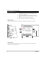
DIN-rail mounting
Snap the device onto the DIN rail as shown below; the module will be squarely situated on the DIN rail.
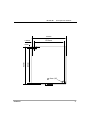
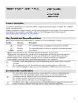
Screw-Mounting
The figure on the next page is drawn to scale. It may be used as a guide for screw-mounting the module.
Mounting screw type: either M3 or NC6-32.
Mounting the Module
80mm
44.5mm
93mm

IO-TO 16
I/O Expansion M odule
Unitronics
3
80mm
5.8mm
68.4mm
4mm
4mm (x2)
93mm
85mm

IO- TO 16
I/O Expansion M odule
4
Unitronics
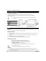
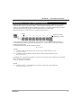
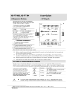
Wiring
An adapter provides the interface between the OPLC and an expansion module. To connect the I/O module to
the adapter or to another module:
1
Push the module-to-module connector into the port located on the right side of the device.
Note that there is a protective cap provided with the adapter. This cap covers the port of the final
I/O module in the system.
■
To avoid damaging the system, do not connect or disconnect the device when the
power is on.
Component identification
1
Module-to-module
connector
2
Protective cap
Wire Size
Use 26-12 AWG wire (0.13 mm 2–3.31 mm2) for all wiring purposes.
Wiring Considerations
■
Note that the adapter, outputs and the power supply for both groups of outputs must be connected to the
same 0V signal.
■
Do not use tin, solder or any other substance on the stripped wire that might cause the wire strand
to break.
■
We recommend that you use crimp terminals for wiring.
■
Install at maximum distance from high-voltage cables and power equipment.
General Wiring Procedures
1 Strip the wire to a length of 7±0.5mm (0.250–0.300 inches).
2 Unscrew the terminal to its widest position before inserting a wire.
3 Insert the wire completely into the terminal to ensure that a proper
connection can be made.
4 Tighten enough to keep the wire from pulling free.
To avoid damaging the wire, do not exceed a maximum torque of 0.5 N·m (5 kgf·m).
■
Do not touch live wires.
■
Double-check all the wiring before turning on the power supply.
I/O Wiring
■
Input or output cables should not be run through the same multi-core cable or share the same wire.
■
Allow for voltage drop and noise interference with output lines used over an extended distance. Use wire
that is properly sized for the load.
Connecting Expansion Modules
1
2

IO-TO 16
I/O Expansion M odule
Unitronics
5
Wiring the Power Supplies to both groups of Outputs
Wiring DC supply
1 First group of outputs: connect the "positive" cable to the "+V0" terminal, and the “negative” to the
"0V” terminal.
2 Second group of outputs: connect the "positive" cable to the "+V1" terminal, and the “negative” to the
"0V” terminal.
■
A non-isolated power supply can be used provided that a 0V signal is connected to the chassis.
■
Do not connect the ‘Neutral’ or ‘Line’ signal of the 110/220VAC to the device’s 0V pin.
■
In the event of voltage fluctuations or non-conformity to voltage power supply specifications, connect the
device to a regulated power supply.
24VDC power supply for
1st group of outputs +V0
0V
Circuit
Load
Protection Device
Circuit Protection
Device
Load
24VDC power supply for
2nd group of outputs
0V
+V1

IO- TO 16
I/O Expansion M odule
6
Unitronics
Max. current consumption 50mA maximum from the adapter’s 5VDC
Typical power consumption 0.12W @ 5VDC
Status indicator
(RUN) Green LED:
—Lit when a communication link is established between module and OPLC.
—Blinks when the communication link fails.
Outputs
Number of outputs 16 pnp (source) in 2 groups
Output type P-MOSFET (open drain), 24VDC
Galvanic isolation None
Output current 0.5A maximum (per output)
Total current: 3A maximum (per group)
Maximum frequency 20Hz (resistive load)
0.5 Hz (inductive load)
Short circuit protection Yes
Status Indicators See Notes
(OUT) Red LEDs—Lit when the corresponding output is active.
(S.C) Red LED—Lit when an output’s load short-circuits.
Operating voltage (per group) 20.4 to 28.8VDC
Nominal operating voltage 24VDC
Environmental IP20
Operating temperature 0 to 50 C
Storage temperature -20 to 60 C
Relative Humidity (RH) 5% to 95% (non-condensing)
Dimensions (WxHxD) 80mm x 93mm x 60mm
Weight 144g (5.08oz.)
Mounting Either onto a 35mm DIN-rail or screw- mounted.
Notes:
1. When an output is connected to a load that short-circuits, that output turns off and the S.C. LED lights
up on the module. Although the output turns off, the LED of that output remains lit.
2. The short circuit is also identified by the software program within the controller connected to the module.
Within the M90 OPLC, for example, SB 5 turns ON. SI 5 contains a bitmap indicating the module
containing the affected output.
For more information, refer to the on-line help supplied with the programming package of your controller.
IO-TO16 Technical Specifications

IO-TO 16
I/O Expansion M odule
Unitronics
7
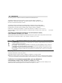
Addressing I/Os on M90 Expansion Modules
Inputs and outputs located on I/O expansion modules that are connected into an M90 OPLC are assigned
addresses that comprise a letter and a number. The letter indicates whether the I/O is an input (I) or an
output (O). The number indicates the I/O’s location in the system. This number relates to both the position
of the expansion module in the system, and to the position of the I/O on that module.
Expansion modules are numbered from 0-7 as shown in the figure below.
Expansion module
identification number
The formula below is used to assign addresses for I/O modules used in conjunction with the M90 OPLC.
X is the number representing a specific module’s location (0-7). Y is the number of the input or output on
that specific module (0-15).
The number that represents the I/O’s location is equal to:
32 + x • 16 + y
Examples
■
Input #3, located on expansion module #2 in the system, will be addressed as I 67,
67 = 32 + 2 • 16 + 3
■
Output #4, located on expansion module #3 in the system, will be addressed as O 84,
84 = 32 + 3 • 16 + 4.
EX90-DI8-RO8 is a stand-alone I/O module. Even if it is the only module in the configuration, the EX90-DI8-
RO8 is always assigned the number 7.
Its I/Os are addressed accordingly.
Example
■
Input #5, located on an EX90-DI8-RO8 connected to an M90 OPLC will be addressed
as I 149, 149 = 32 + 7 • 16 + 5
Adapter
0 1 2 3 4 5 6 7

UL Compliance
The following section is relevant to Unitronics’ products that are listed with the UL.
The following models: IO-AI4-AO2, IO-AO6X, IO-ATC8, IO-DI16, IO-DI16-L, IO-DI8-RO4,
IO-DI8-RO4-L, IO-DI8-TO8, IO-DI8-TO8-L, IO-RO16, IO-RO16-L, IO-RO8, IO-RO8L, IO-TO16,
EX-A2X are UL listed for Hazardous Locations.
The following models: EX-D16A3-RO8, EX-D16A3-RO8L, EX-D16A3-TO16, EX-D16A3-TO16L,
IO-AI1X-AO3X, IO-AI4-AO2, IO-AI4-AO2-B, IO-AI8, IO-AI8Y, IO-AO6X, IO-ATC8, IO-D16A3-RO16,
IO-D16A3-RO16L, IO-D16A3-TO16, IO-D16A3-TO16L, IO-DI16, IO-DI16-L, IO-DI8-RO4,
IO-DI8-RO4-L, IO-DI8-RO8, IO-DI8-RO8-L, IO-DI8-TO8, IO-DI8-TO8-L, IO-DI8ACH, IO-LC1, IO-LC3,
IO-PT4, IO-PT400, IO-PT4K, IO-RO16, IO-RO16-L, IO-RO8, IO-RO8L, IO-TO16, EX-A2X, EX-RC1 are UL listed for
Ordinary Location.
UL Ratings, Programmable Controllers for Use in Hazardous Locations,
Class I, Division 2, Groups A, B, C and D
These Release Notes relate to all Unitronics products that bear the UL symbols used to mark products that have been
approved for use in hazardous locations, Class I, Division 2, Groups A, B, C and D.
Caution
◼ This equipment is suitable for use in Class I, Division 2, Groups A, B, C and D, or Non-hazardous
locations only.
◼ Input and output wiring must be in accordance with Class I, Division 2 wiring methods and in accordance
with the authority having jurisdiction.
◼ WARNING—Explosion Hazard—substitution of components may impair suitability for Class I, Division 2.
◼ WARNING – EXPLOSION HAZARD – Do not connect or disconnect equipment unless power has been
switched off or the area is known to be non-hazardous.
◼ WARNING – Exposure to some chemicals may degrade the sealing properties of material used in Relays.
◼ This equipment must be installed using wiring methods as required for Class I, Division 2 as per the NEC
and/or CEC.
Relay Output Resistance Ratings
The products listed below contain relay outputs:
Input/Output expansion modules, Models: IO-DI8-RO4, IO-DI8-RO4-L, IO-RO8, IO-RO8L
◼ When these specific products are used in hazardous locations, they are rated at 3A res, when these specific products
are used in non-hazardous environmental conditions, they are rated at 5A res, as given in the product’s specifications.
Certification UL des automates programmables, pour une utilisation en
environnement à risques, Class I, Division 2, Groups A, B, C et D.
Cette note fait référence à tous les produits Unitronics portant le symbole UL - produits qui ont été certifiés pour une
utilisation dans des endroits dangereux, Classe I, Division 2, Groupes A, B, C et D.

IO-TO 16
I/O Expansion M odule
Unitronics
9
Attention
◼ Cet équipement est adapté pour une utilisation en Classe I, Division 2, Groupes A, B, C et
D, ou dans Non-dangereux endroits seulement.
◼ Le câblage des entrées/sorties doit être en accord avec les méthodes
de câblage selon la Classe I, Division 2 et en accord avec l’autorité compétente.
◼ AVERTISSEMENT: Risque d’Explosion – Le remplacement de certains composants rend caduque la
certification du produit selon la Classe I, Division 2.
◼ AVERTISSEMENT - DANGER D'EXPLOSION - Ne connecter pas ou ne débranche pas l'équipement sans
avoir préalablement coupé l'alimentation électrique ou la zone est reconnue pour être non dangereuse.
◼ AVERTISSEMENT - L'exposition à certains produits chimiques peut dégrader les propriétés des matériaux
utilisés pour l'étanchéité dans les relais.
◼ Cet équipement doit être installé utilisant des méthodes de câblage suivant la norme Class I, Division 2 NEC
et /ou CEC.
Certification de la résistance des sorties relais
Les produits énumérés ci-dessous contiennent des sorties relais:
◼ Modules d’Extensions d'E/S, modèles: IO-DI8-RO4, IO-DI8-RO4-L, IO-RO8, IO-RO8L.
◼ Lorsque ces produits spécifiques sont utilisés dans des endroits dangereux, ils supportent
un courant de 3A charge résistive, lorsque ces produits spécifiques sont utilisés dans un environnement non
dangereux, ils sont évalués à 5A res, comme indiqué dans les specifications du produit Plages de températures.
The information in this document reflects products at the date of printing. Unitronics reserves the right, subject to all applicable laws, at any
time, at its sole discretion, and without notice, to discontinue or change the features, designs, materials and other specifications of
its products, and to either permanently or temporarily withdraw any of the forgoing from the market.
All information in this document is provided "as is" without warranty of any kind, either expressed or implied, including but not limited to any
implied warranties of merchantability, fitness for a particular purpose, or non-infringement. Unitronics assumes no responsibility for errors or
omissions in the information presented in this document. In no event shall Unitronics be liable for any special, incidental, indirect or
consequential damages of any kind, or any damages whatsoever arising out of or in connection with the use or performance of this
information.
The tradenames, trademarks, logos and service marks presented in this document, including their design, are the property of Unitronics
(1989) (R"G) Ltd. or other third parties and you are not permitted to use them without the prior written consent of Unitronics or such third party
as may own them.
UG_IO-TO16.pdf 11/22
-
 1
1
-
 2
2
-
 3
3
-
 4
4
-
 5
5
-
 6
6
-
 7
7
-
 8
8
-
 9
9


Unitronics IO-TO16 I/O Expansion Module Manuel utilisateur
- Taper
- Manuel utilisateur
dans d''autres langues
Documents connexes
-
Unitronics IO-ATC8 Manuel utilisateur
-
 Unitronics EX-RC1 Remote I/O Adapter Mode d'emploi
-
 Unitronics IO-PT400 I-O Expansion Modules Mode d'emploi
-
 Unitronics EX-RC1 Remote Input or Output Adapter Mode d'emploi
-
Unitronics V1210-T20BJ Mode d'emploi
-
Unitronics V530-53-B20B Mode d'emploi
-
Unitronics JZ20-R31 HMI Display Unit Mode d'emploi
-
 Unitronics V120-22-R1 PLC Controllers Mode d'emploi
-
 Unitronics V120 Rugged Programmable Logic Controllers Mode d'emploi
-
 Unitronics V120-22-R34 Display units and HMIs Mode d'emploi


Autres documents
-
Danfoss AK-PC 572 Guide d'installation
-
SBC PCD1.B1010-A20 L-Series RIO 24DI, 10Rel Fiche technique
-
Eurotherm T2750 Mode d'emploi
-
-
-
-
-