Dometic PerfectWall PW3500 Guide d'installation
- Taper
- Guide d'installation

1
PW3500 4,7 m – 5 m
PW3500 2,5 m – 4 m
Ø 11 mm
A
A = W – 2 mm
B = W + 14 mm
W
B
A
B
1
2
10
11
12
13
14
15
16
17
18
19
4
3
5
6
7
8
9
1x
1x
1x
1x
a
b
c
d
e
PW3500
1
2
5
6
3
4
7
9
0
8

2
5 - 9 Nm
20 – 22 Nm
16 – 18 Nm
2.
3.
3.
4.
1.
DC1146E
Dometic Premium PW3500
ws
or
rt
sw
rt
sw
bl
T15A
br
T3A
D+
2.
1.
1.
3
1
2
e
f
j
b
i
c
h
ga
d
k
4445100630 F 02/2020
YOUR LOCAL DEALER
dometic.com/dealer
A complete list of Dometic companies, which comprise the Dometic Group, can be found in the public filings of:
DOMETIC GROUP AB Hemvärnsgatan 15 SE-17154 Solna Sweden
YOUR LOCAL SUPPORT
dometic.com/contact
YOUR LOCAL SALES OFFICE
dometic.com/sales-offices

PW3500
Premium Awning
Installation Manual. . . . . . . . . . . . . . . . . . . . . 3
Premium Markise
Montageanleitung. . . . . . . . . . . . . . . . . . . . 12
Auvent premium
Instructions de montage . . . . . . . . . . . . . . .22
Told o Premi um
Instrucciones de montaje . . . . . . . . . . . . . .32
Told o Premi um
Instruções de montagem . . . . . . . . . . . . . . 41
Marquise Premium
Indicazioni di montaggio . . . . . . . . . . . . . . 51
Premium zonnescherm
Montagehandleiding . . . . . . . . . . . . . . . . . 61
Premium markise
Monteringsvejledning. . . . . . . . . . . . . . . . . 71
Premium markis
Monteringsanvisning. . . . . . . . . . . . . . . . . .80
Premium markise
Monteringsanvisning. . . . . . . . . . . . . . . . . .89
Premium-markiisi
Asennusohje . . . . . . . . . . . . . . . . . . . . . . . .98
Автомобильная шторка
«Premium»
Инструкция по монтажу. . . . . . . . . . . . . . 107
Markiza Premium
Instrukcja montażu . . . . . . . . . . . . . . . . . . 117
Markýza Premium
Návod k montáži . . . . . . . . . . . . . . . . . . . . 127
Premium markiza
Navodilo za montažo . . . . . . . . . . . . . . . . 136
Τέντα Premium
Οδηγίες τοποθέτησης. . . . . . . . . . . . . . 145
EN
DE
FR
ES
PT
IT
NL
DA
SV
NO
FI
RU
PL
CS
SL
EL
AWNINGS
PERFECTWALL
PW3500-I-16s.book Seite 1 Freitag, 23. September 2016 3:13 15

PW3500-I-16s.book Seite 2 Freitag, 23. September 2016 3:13 15

EN
PW3500
3
!
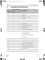
Table of contents
1 Explanation of symbols. . . . . . . . . . . . . . . . . . . . . . . . . . . . . . . . . . . . . . . . . . .4
2 Important safety instructions for installation. . . . . . . . . . . . . . . . . . . . . . . . . . .4
3 Scope of delivery . . . . . . . . . . . . . . . . . . . . . . . . . . . . . . . . . . . . . . . . . . . . . . .5
4 Accessories . . . . . . . . . . . . . . . . . . . . . . . . . . . . . . . . . . . . . . . . . . . . . . . . . . . .6
5 Intended use . . . . . . . . . . . . . . . . . . . . . . . . . . . . . . . . . . . . . . . . . . . . . . . . . . .6
6 Instructions before installation . . . . . . . . . . . . . . . . . . . . . . . . . . . . . . . . . . . . .7
7 Installing the awning . . . . . . . . . . . . . . . . . . . . . . . . . . . . . . . . . . . . . . . . . . . . .8
8 Connecting electrical power to the awning . . . . . . . . . . . . . . . . . . . . . . . . .10
9 Check the functions . . . . . . . . . . . . . . . . . . . . . . . . . . . . . . . . . . . . . . . . . . . . 11
10 Disposal . . . . . . . . . . . . . . . . . . . . . . . . . . . . . . . . . . . . . . . . . . . . . . . . . . . . . . 11
WARNING!
• This manual must be read and understood before installation,
adjustment, service or maintenance is performed. This unit must be
installed by a qualified service technician. Incorrect installation can
lead to severe injury. Follow all installation instructions. Modification
of this product can be extremely hazardous and could result in
personal injury or property damage.
• These instructions must stay with unit. Owner read carefully.
PW3500-I-16s.book Seite 3 Freitag, 23. September 2016 3:13 15

EN
Explanation of symbols PW3500
4
1 Explanation of symbols
!
A
I
2 Important safety instructions for
installation
Please observe the prescribed safety instructions and stipulations from the
vehicle manufacturer and service workshops.
The manufacturer accepts no liability for damage in the following cases:
• Damage to the product resulting from mechanical influences and excess voltage
• Alterations to the product without express permission from the manufacturer
• Use for purposes other than those described in the operating manual
!
WARNING!
• If you do not have sufficient technical knowledge for installing
components in vehicles, you should have a specialist fit the awning to
your vehicle.
• The electrical connections should only be performed by an electrician.
WARNING!
Safety instruction: Failure to observe this instruction can cause fatal or
serious injury.
NOTICE!
Failure to observe this instruction can cause material damage and impair
the function of the product.
NOTE
Supplementary information for operating the product.
PW3500-I-16s.book Seite 4 Freitag, 23. September 2016 3:13 15

EN
PW3500 Scope of delivery
5
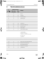
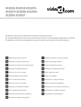
3Scope of delivery
No. in
fig. 1
Awning width
Description
2.5 m, 3.1 m,
3.5 m, 4 m
4.7 m,
5m
11x1xAwning
2 3x 4x Backer plate
3 3x 4x Cover for the backer plate
4 1x 1x Mounting bracket
5 12x 16x Lock nut M6
6 12x 16x Washer
7 12x 16x Spacer sleeves
8 12x 16x Fastening screw M6 x 50
9 6x 8x Self-tapping screw
10 1x 1x Remote control
11 1x 1x Remote control holder
12 1x 1x Receiver
a: Voltage supply
b: Awning motor
c: Awning light (accessory)
d: Ignition
e: Antenna
13 1x 1x 15 A fuse (including bracket)
14 1x 1x Plug for D+ connection
15 1x 1x Plug for LED awning light
16 1x 1x Plug for motor connection
17 1x 1x Plug for voltage supply
18 1x 1x Main switch (including plug)
19 1x 1x Adjustment tool
– 1x 1x Wind sensor (premounted)
PW3500-I-16s.book Seite 5 Freitag, 23. September 2016 3:13 15

EN
Accessories PW3500
6
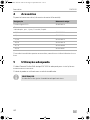
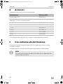
4Accessories
Available as accessories (not included in the scope of delivery):
If you have questions in respect of the accessories, please contact your local service
partner.
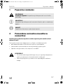
5 Intended use
The Dometic PerfectWall Awning Type PW3500 is suitable for installing on
motorhomes or caravans.
The awning may only be used whilst the vehicle is stationary.
I
Description Ref. no.
Dometic Light LK120 9106504018
Mounting bracket,
suitable for e.g. für Hymer, Euramobil, Rapido
– 2.5 m 9103500513
– 3.1 m 9103500514
– 3.5 m 9103500515
– 4.0 m 9103500579
– 4.7 m 9103500580
– 5.0 m 9103500581
NOTE
The tolerances of the gap dimensions are due to design.
PW3500-I-16s.book Seite 6 Freitag, 23. September 2016 3:13 15

EN
PW3500 Instructions before installation
7
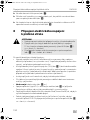
6 Instructions before installation
The mounting bracket is attached behind the shoulder joints (left, right and centre)
with bolts that pass through the structure. In addition it is glued to the wall
(with Sikaflex
®
-252 for example) to prevent water leakage.
When choosing the installation location, observe the following:
!
WARNING!
• A horizontal distance of at least 40 cm must be maintained between
the fully open awning and any permanent object.
• Make sure the RV structure will safely and securely support awning
before installation. Otherwise, the cassette awning may become
unstable and could bend or collapse.
• Select a height of more than 2.5 m above ground or other level that
could provide access to it.
A
NOTICE!
• Only attach the awning to flat and vertical wall surfaces (fig. 2 and
fig. 3). On curved wall surfaces, the mounting bracket needs to be
adequately supported under the fastening points.
• Ensure that the living space door opens without coming into contact
with parts of the awning (fig. 4). Pay particular attention to the
pivoting range of the awning arms.
• If the awning ends in the middle of a window or flap, you cannot use
the accessory MyRoom (fig. 5).
• Check whether there is enough space available on the inside, for
mounting the backer plates.
A backer plate must be mounted behind each of the shoulder joints of
the awning! (fig. 6)
• Before drilling holes ensure no cables and cabinets in the interior of
the vehicle will be damaged.
I
NOTE
Point out to the user of the vehicle that the three screws on the shoulder
joints (fig. j) must be tightened up (see operating manual). This must be
done by the service partner.
PW3500-I-16s.book Seite 7 Freitag, 23. September 2016 3:13 15

EN
Installing the awning PW3500
8
7 Installing the awning
7.1 Required installation material
For the installation of the awning, you will need:
• Drill bits: ∅ 8 mm and 11 mm
• Counterbore
• Metal saw
• 10 mm open-ended spanner or connection socket
• Torque wrench
• Phillips screwdriver or bit
• A suitable flexible adhesive/sealant, such as Sikaflex
®
-252 for example
• Cleaner recommended for use with the adhesive
• Primer recommended for use with the adhesive
7.2 Installing the awning
A
➤ Remove the awning from the premounted mounting bracket (fig. 7).
➤ Determine the location of the installation.
In particular, check that there is enough space in the interior to mount the backer
plates at the points where the screws will be.
I
➤ Align the mounting bracket on the vehicle and mark where the holes are to be
drilled (fig. 8).
NOTICE!
• Always install the mounting bracket using the supplied spacer
sleeves, shortened to 2 mm less than the thickness of the external
wall. Otherwise, the awning can break off and cause serious injury.
• Make sure that you do not damage any cables or cabinets when
drilling.
NOTE
The recommended mounting position for each counter plate is shown in
fig. 8 A.
If any objects are obstructing this mounting position for the counter
plates, you can mount the counter plates as shown in fig. 8 B:
• Choose a drill hole from the four drill hole pairs.
• Fasten each counter plate with four screws.
PW3500-I-16s.book Seite 8 Freitag, 23. September 2016 3:13 15

EN
PW3500 Installing the awning
9
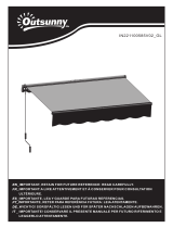
➤ At the marked points, drill holes with a diameter of 11 mm from the outside
through the external wall (fig. 9).
➤ Shorten the spacer sleeves to the size A = wall thickness W – 2 mm (fig. 0).
➤ Insert the spacing sleeves into the holes from the outside.
➤ Trim the fastening screws to size B = wall thickness W + 14 mm (fig. 0).
A
➤ Clean the adherends on the mounting bracket and the wall.
➤ Prepare the adherends with the primer.
➤ To glue and seal apply an elastic adhesive, such as Sikaflex
®
-252 for example, to
the back of the mounting bracket (fig. a).
Ensure to seal the holes properly to avoid moisture in the RV wall.
➤ Lift the mounting bracket to the wall (fig. b).
➤ Install the mounting brackets with backer plates, fastening screws, spacer
sleeves, washers, holder rings and nuts (fig. c).
Tighten the bolts to 5 – 9 Nm.
➤ Wait until the glue has set. For further details, please refer to the information
provided by the sealant manufacturer.
➤ Use a screwdriver to loosen the two tabs on the right-hand cap cover (fig. d)
and remove the cap cover.
➤ Use two people to hook the awning on to the mounting bracket (fig. e).
Check whether the awning has been properly hooked and that it is flush against
the wall.
!
➤ Fasten the awning to the mounting bracket with the self-tapping bolts (fig. f).
➤ Connect the awning electrically (see chapter “Connecting electrical power to the
awning” on page 10).
Contact a qualified electrician to ensure compliance with all legislative
regulations.
➤ Put on the right-hand cap cover (fig. g).
NOTICE!
Observe the sealant manufacturer's instructions.
WARNING!
Do not open the awning or leave it unattended, before the awning has
been fastened to the mounting bracket.
PW3500-I-16s.book Seite 9 Freitag, 23. September 2016 3:13 15

EN
Connecting electrical power to the awning PW3500
10
➤ Inside the vehicle, press the covers on the counter plates until the two tabs click
into the counter plates (fig. h).
➤ Attach the wall bracket for the remote control at a suitable location inside of the
RV and protected against direct sunlight (fig. i).
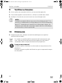
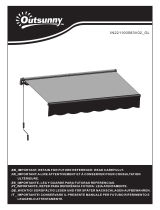
8 Connecting electrical power to the
awning
!
Observe the following installation instructions:
• The selected voltage supply must ensure that the awning is always supplied with
power while in operation (even in the extended state). If this is not the case, the
wind sensor is switched off which presents a safety risk.
• Install the main switch and fuse (15 A) (fig. k 3) included, in the positive cable of
the voltage supply. The main switch is required to switch off the awning if, for
example, an awning tent is being installed or if the vehicle is not being used for a
longer period of time (otherwise the standby consumption can run down the
battery).
• Install the receiver inside the vehicle to protect it from damp and wet.
• Observe the length of the cable between the awning motor and receiver when
choosing a place to install it.
• Do not shorten the antenna cable (fig. k ws).
• Connect the ignition (D+ signal) with the orange cable (fig. k or) on the
receiver. This ensures that the awning cannot be opened when driving along.
• Use a suitable tool (crimping tool) when installing the plug supplied to ensure
that the connection is secure and long-lasting.
• If you would like to fit an awning light (accessory), make sure that the maximum
power consumption is 30 W. Make sure that the polarity is correct when
connecting (fig. k, sw = black, rt = red).
• When connecting the receiver to the voltage supply, adhere to the required
cable cross section:
WARNING!
• Only a qualified electrician should connect the awning to the
electrical power.
• Wire to a 12 Vg power source with correct polarity that is able to
provide 80 W (fig. k 1, sw = black, rt = red).
• Make sure that the polarity is correct when connecting the awning
motor (fig. k 2, br = brown, bl = blue).
PW3500-I-16s.book Seite 10 Freitag, 23. September 2016 3:13 15

EN
PW3500 Check the functions
11
➤ Make wiring connections in compliance with all applicable electrical codes.
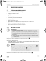
9 Check the functions
➤ Insert the batteries into the remote control; see the operating manual.
➤ With power applied to the awning check that the awning opens and retracts.
➤ Check that the wind sensor functions (see Operation manual).
A
10 Disposal
➤ Place the packaging material in the appropriate recycling waste bins wherever
possible.
M
If you wish to finally dispose of the product, ask your local recycling centre
or specialist dealer for details about how to do this in accordance with the
applicable disposal regulations.
B
Protect the environment!
Do not dispose of any batteries with general household waste.
Return defective or used batteries to your retailer or dispose of them at
collection points.
Total Cable Length Recommended Wire Cross Section
2 m 1,5 mm²
4 m 2,5 mm²
6 m 4,0 mm²
8 m 6,0 mm²
NOTICE!
The cassette awning is factory preset for a 5° fabric tilt angle.
Alternatively, the awning can have an adjustable pitch of up to 15°,
as long as there is sufficient space to the door etc.
Any adjustment of this hardware must be performed by a qualified
service technician only.
PW3500-I-16s.book Seite 11 Freitag, 23. September 2016 3:13 15

DE
PW3500
12
!
Inhaltsverzeichnis
1 Erklärung der Symbole . . . . . . . . . . . . . . . . . . . . . . . . . . . . . . . . . . . . . . . . . .13
2 Wichtige Sicherheits- und Einbauhinweise . . . . . . . . . . . . . . . . . . . . . . . . . .13
3 Lieferumfang . . . . . . . . . . . . . . . . . . . . . . . . . . . . . . . . . . . . . . . . . . . . . . . . . .14
4 Zubehör. . . . . . . . . . . . . . . . . . . . . . . . . . . . . . . . . . . . . . . . . . . . . . . . . . . . . .15
5 Bestimmungsgemäßer Gebrauch . . . . . . . . . . . . . . . . . . . . . . . . . . . . . . . . .15
6 Hinweise vor der Montage. . . . . . . . . . . . . . . . . . . . . . . . . . . . . . . . . . . . . . .16
7 Markise montieren . . . . . . . . . . . . . . . . . . . . . . . . . . . . . . . . . . . . . . . . . . . . .17
8 Markise elektrisch anschließen. . . . . . . . . . . . . . . . . . . . . . . . . . . . . . . . . . . .19
9 Funktion prüfen . . . . . . . . . . . . . . . . . . . . . . . . . . . . . . . . . . . . . . . . . . . . . . . 20
10 Entsorgung . . . . . . . . . . . . . . . . . . . . . . . . . . . . . . . . . . . . . . . . . . . . . . . . . . .21
WARNUNG!
• Diese Anleitung muss vor der Installation, dem Einrichten, dem
Betrieb und der Wartung gelesen und verstanden werden. Dieses
Gerät muss von einer Fachkraft installiert werden. Eine fehlerhafte
Installation kann zu schweren Verletzungen führen. Umbauten am
Gerät können äußerst gefährlich werden und zu schweren
Verletzungen oder zu Geräteschäden führen.
• Diese Anleitung muss beim Gerät verbleiben. Der Besitzer muss sie
aufmerksam lesen.
PW3500-I-16s.book Seite 12 Freitag, 23. September 2016 3:13 15

DE
PW3500 Erklärung der Symbole
13
1 Erklärung der Symbole
!
A
I
2 Wichtige Sicherheits- und
Einbauhinweise
Beachten Sie die vom Fahrzeughersteller und vom Kfz-Handwerk
vorgeschriebenen Sicherheitshinweise und Auflagen!
Der Hersteller übernimmt in folgenden Fällen keine Haftung für Schäden:
• Beschädigungen am Produkt durch mechanische Einflüsse und
Überspannungen
• Veränderungen am Produkt ohne ausdrückliche Genehmigung vom Hersteller
• Verwendung für andere als die in der Anleitung beschriebenen Zwecke
!
WARNUNG!
• Wenn Sie nicht über ausreichende technische Kenntnisse zum
Einbauen von Komponenten in Fahrzeugen verfügen, sollten Sie sich
die Markise von einem Fachmann ans Fahrzeug montieren lassen.
• Lassen Sie elektrische Anschlüsse nur von fachkundigem Personal
ausführen.
WARNUNG!
Sicherheitshinweis: Nichtbeachtung kann zu Tod oder schwerer
Verletzung führen.
ACHTUNG!
Nichtbeachtung kann zu Materialschäden führen und die Funktion des
Produktes beeinträchtigen.
HINWEIS
Ergänzende Informationen zur Bedienung des Produktes.
PW3500-I-16s.book Seite 13 Freitag, 23. September 2016 3:13 15

DE
Lieferumfang PW3500
14
3 Lieferumfang
Nr. in
Abb. 1
Markisenbreite
Bezeichnung
2,5 m, 3 m,
3,5 m, 4 m
4,7 m,
5m
1 1x 1x Markise
2 3x 4x Gegenplatte
3 3x 4x Abdeckung für Gegenplatte
4 1x 1x Montageschiene
5 12x 16x Mutter M6
6 12x 16x Unterlegscheibe
7 12x 16x Distanzhülsen
8 12x 16x Befestigungsschraube M6 x 50
9 6x 8x Selbstschneidende Schraube
10 1x 1x Fernbedienung
11 1x 1x Halter für Fernbedienung
12 1x 1x Empfänger
a: Spannungsversorgung
b: Markisenmotor
c: Markisenlicht (Zubehör)
d: Zündung
e: Antenne
13 1x 1x 15-A-Sicherung (einschließlich Halter)
14 1x 1x Stecker für D+-Anschluss
15 1x 1x Stecker für LED-Markisenlicht
16 1x 1x Stecker für Motoranschluss
17 1x 1x Stecker für Spannungsversorgung
18 1x 1x Hauptschalter (einschließlich Stecker)
19 1x 1x Einstellwerkzeug
– 1x 1x Windsensor (vormontiert)
PW3500-I-16s.book Seite 14 Freitag, 23. September 2016 3:13 15

DE
PW3500 Zubehör
15
4Zubehör
Als Zubehör erhältlich (nicht im Lieferumfang enthalten):
Bei Fragen zu Zubehör wenden Sie sich bitte an Ihren Service-Partner.
5 Bestimmungsgemäßer Gebrauch
Die Dometic PerfectWall Markise PW3500 ist geeignet zum Anbau an Wohnmobile
oder Wohnwagen.
Die Markise darf nur im Stand benutzt werden.
I
Bezeichnung Artikelnummer
Dometic Light LK120 9106504018
Sonderschiene,
passend z. B. für Hymer, Euramobil, Rapido
– 2,5 m 9103500513
– 3,1 m 9103500514
– 3,5 m 9103500515
– 4,0 m 9103500579
– 4,7 m 9103500580
– 5,0 m 9103500581
HINWEIS
Toleranzen bei den Spaltmaßen sind konstruktionsbedingt.
PW3500-I-16s.book Seite 15 Freitag, 23. September 2016 3:13 15

DE
Hinweise vor der Montage PW3500
16
6 Hinweise vor der Montage
Die Montageschiene wird hinter den Schultergelenken (links, rechts und Mitte) mit
Schrauben gesichert werden, die durch den Aufbau gehen. Zusätzlich wird sie auf
die Wand geklebt (z. B. mit Sikaflex
®
-252), um Wassereintritt zu vermeiden.
Beachten Sie bei der Wahl des Einbauortes Folgendes:
!
WARNUNG!
• Halten Sie horizontal einen Abstand von mindestens 40 cm zwischen
der vollständig geöffneten Markise und jeglichen dauerhaften
Objekten ein.
• Stellen Sie vor der Installation sicher, dass die Wohnmobilwand die
Markise sicher tragen kann. Sonst kann die Markise instabil werden
und sich verbiegen oder abbrechen.
• Wählen Sie eine Höhe von über 2,5 m über dem Boden oder anderen
Ebenen, die Zugriff auf die Markise bieten.
A
ACHTUNG!
• Montieren Sie die Markise nur an planen und lotrechten Wandflächen
(Abb. 2 und Abb. 3). Bei gewölbten Wandflächen müssen Sie die
Montageschiene an den Befestigungsstellen ausreichend
unterfüttern.
• Stellen Sie sicher, dass die Wohnraumtür aufgeht, ohne Teile der
Markise zu berühren (Abb. 4). Beachten Sie insbesondere den
Schwenkbereich der Markisenarme.
• Wenn die Markise mitten über einem Fenster oder einer Klappe
endet, können Sie das Zubehör MyRoom nicht benutzen (Abb. 5).
• Prüfen Sie, ob im Inneren ausreichend Platz zum Montieren der
Gegenplatten vorhanden ist.
Hinter allen Schultergelenken der Markise muss eine Gegenplatte
montiert werden (Abb. 6).
• Leitungen und Einbauschränke im Fahrzeuginnenraum dürfen beim
Bohren nicht beschädigt werden.
I
HINWEIS
Weisen Sie den Benutzer des Fahrzeugs darauf hin, dass die drei
Schrauben am Schultergelenk (Abb. j) nachgezogen werden müssen
(siehe Bedienungsanleitung). Dies muss durch den Service-Partner
erfolgen.
PW3500-I-16s.book Seite 16 Freitag, 23. September 2016 3:13 15

DE
PW3500 Markise montieren
17
7Markise montieren
7.1 Benötigtes Montagematerial
Für die Montage der Markise benötigen Sie:
• Bohrer mit ∅ 8 mm und 11 mm
• Senker
• Metallsäge
• 10 mm Gabelschlüssel oder Steckschlüssel
• Drehmomentschlüssel
• Kreuzschlitz-Schraubendreher oder -Bit
• Geeigneter elastischer Kleber/Dichtmittel wie z. B. Sikaflex
®
-252
• Reiniger, der zur Verwendung mit dem Kleber empfohlen ist
• Primer, der zur Verwendung mit dem Kleber empfohlen ist
7.2 Markise montieren
A
➤ Lösen Sie die Markise aus der vormontierten Montageschiene (Abb. 7).
➤ Legen Sie den Montageort fest.
Prüfen Sie insbesondere, ob an den Stellen, an denen die Verschraubungen sein
werden, genügend Platz für die Montage der Gegenplatten im Innenraum ist.
I
ACHTUNG!
• Montieren Sie die Montageschiene immer mit den beiliegenden
Distanzhülsen, die auf die Dicke der Außenwand minus 2 mm
gekürzt wurden. Sonst kann es zu Wassereintritt und bleibenden
Schäden am Fahrzeug kommen.
• Stellen Sie sicher, dass Sie beim Bohren keine Leitungen oder
Einbauschränke beschädigen.
HINWEIS
Die empfohlene Montageposition für jede Gegenplatte ist in Abb. 8 A
dargestellt.
Falls für eine oder mehrere Gegenplatten Objekte diese
Montageposition behindern, können Sie diese Gegenplatten
entsprechend Abb. 8 B montieren:
• Wählen Sie aus den vier Bohrungspaaren eine Bohrung aus.
• Befestigen Sie jede Gegenplatte mit vier Schrauben.
PW3500-I-16s.book Seite 17 Freitag, 23. September 2016 3:13 15

DE
Markise montieren PW3500
18
➤ Richten Sie die Montageschiene am Fahrzeug aus und zeichnen Sie die
Bohrungen vor (Abb. 8).
➤ Bohren Sie an den angezeichneten Stellen von außen Löcher mit einem
Durchmesser von 11 mm durch die Außenwand (Abb. 9).
➤ Kürzen Sie die Distanzhülsen auf das Maß A = Wandstärke W – 2 mm (Abb. 0).
➤ Stecken Sie die Distanzhülsen von außen in die Bohrungen.
➤ Kürzen Sie die Befestigungsschrauben auf das Maß B = Wandstärke W + 14 mm
(Abb. 0).
A
➤ Reinigen Sie die Klebeflächen auf der Montageschiene und der Wand.
➤ Bereiten Sie die Klebeflächen mit dem Primer vor.
➤ Tragen Sie zum Kleben und Abdichten auf die Rückseite der Montageschiene
einen elastischen Kleber wie z. B. Sikaflex
®
-252 auf (Abb. a).
Dichten Sie die Bohrungen sorgfältig ab, um Feuchtigkeit in der
Wohnmobilwand zu verhindern.
➤ Heben Sie die Montageschiene an die Wand (Abb. b).
➤ Montieren Sie die Montageschiene mit Gegenplatten, Befestigungsschrauben,
Distanzhülsen, Unterlegscheiben, Sicherungsringen und Muttern (Abb. c).
Ziehen Sie die Schrauben mit 5 – 9 Nm an.
➤ Warten Sie, bis der Kleber ausgehärtet ist. Nähere Angaben entnehmen Sie den
Informationen des Dichtmittel-Herstellers.
➤ Entriegeln Sie mit einem Schraubendreher die beiden Laschen an der rechten
Endkappe (Abb. d) und nehmen Sie die Endkappe ab.
➤ Hängen Sie die Markise mit zwei Personen in die Montageschiene (Abb. e).
Prüfen Sie, ob die Markise richtig eingehängt ist und plan an der Wand anliegt.
!
➤ Fixieren Sie die Markise mit den selbstschneidenden Schrauben an der
Montageschiene (Abb. f).
ACHTUNG!
Beachten Sie die Hinweise des Dichtmittel-Herstellers.
WARNUNG!
Fahren Sie die Markise nicht aus und lassen Sie sie nicht unbeaufsichtigt,
solange die Markise noch nicht an der Montageschiene fixiert ist.
PW3500-I-16s.book Seite 18 Freitag, 23. September 2016 3:13 15
La page est en cours de chargement...
La page est en cours de chargement...
La page est en cours de chargement...
La page est en cours de chargement...
La page est en cours de chargement...
La page est en cours de chargement...
La page est en cours de chargement...
La page est en cours de chargement...
La page est en cours de chargement...
La page est en cours de chargement...
La page est en cours de chargement...
La page est en cours de chargement...
La page est en cours de chargement...
La page est en cours de chargement...
La page est en cours de chargement...
La page est en cours de chargement...
La page est en cours de chargement...
La page est en cours de chargement...
La page est en cours de chargement...
La page est en cours de chargement...
La page est en cours de chargement...
La page est en cours de chargement...
La page est en cours de chargement...
La page est en cours de chargement...
La page est en cours de chargement...
La page est en cours de chargement...
La page est en cours de chargement...
La page est en cours de chargement...
La page est en cours de chargement...
La page est en cours de chargement...
La page est en cours de chargement...
La page est en cours de chargement...
La page est en cours de chargement...
La page est en cours de chargement...
La page est en cours de chargement...
La page est en cours de chargement...
La page est en cours de chargement...
La page est en cours de chargement...
La page est en cours de chargement...
La page est en cours de chargement...
La page est en cours de chargement...
La page est en cours de chargement...
La page est en cours de chargement...
La page est en cours de chargement...
La page est en cours de chargement...
La page est en cours de chargement...
La page est en cours de chargement...
La page est en cours de chargement...
La page est en cours de chargement...
La page est en cours de chargement...
La page est en cours de chargement...
La page est en cours de chargement...
La page est en cours de chargement...
La page est en cours de chargement...
La page est en cours de chargement...
La page est en cours de chargement...
La page est en cours de chargement...
La page est en cours de chargement...
La page est en cours de chargement...
La page est en cours de chargement...
La page est en cours de chargement...
La page est en cours de chargement...
La page est en cours de chargement...
La page est en cours de chargement...
La page est en cours de chargement...
La page est en cours de chargement...
La page est en cours de chargement...
La page est en cours de chargement...
La page est en cours de chargement...
La page est en cours de chargement...
La page est en cours de chargement...
La page est en cours de chargement...
La page est en cours de chargement...
La page est en cours de chargement...
La page est en cours de chargement...
La page est en cours de chargement...
La page est en cours de chargement...
La page est en cours de chargement...
La page est en cours de chargement...
La page est en cours de chargement...
La page est en cours de chargement...
La page est en cours de chargement...
La page est en cours de chargement...
La page est en cours de chargement...
La page est en cours de chargement...
La page est en cours de chargement...
La page est en cours de chargement...
La page est en cours de chargement...
La page est en cours de chargement...
La page est en cours de chargement...
La page est en cours de chargement...
La page est en cours de chargement...
La page est en cours de chargement...
La page est en cours de chargement...
La page est en cours de chargement...
La page est en cours de chargement...
La page est en cours de chargement...
La page est en cours de chargement...
La page est en cours de chargement...
La page est en cours de chargement...
La page est en cours de chargement...
La page est en cours de chargement...
La page est en cours de chargement...
La page est en cours de chargement...
La page est en cours de chargement...
La page est en cours de chargement...
La page est en cours de chargement...
La page est en cours de chargement...
La page est en cours de chargement...
La page est en cours de chargement...
La page est en cours de chargement...
La page est en cours de chargement...
La page est en cours de chargement...
La page est en cours de chargement...
La page est en cours de chargement...
La page est en cours de chargement...
La page est en cours de chargement...
La page est en cours de chargement...
La page est en cours de chargement...
La page est en cours de chargement...
La page est en cours de chargement...
La page est en cours de chargement...
La page est en cours de chargement...
La page est en cours de chargement...
La page est en cours de chargement...
La page est en cours de chargement...
La page est en cours de chargement...
La page est en cours de chargement...
La page est en cours de chargement...
La page est en cours de chargement...
La page est en cours de chargement...
La page est en cours de chargement...
La page est en cours de chargement...
La page est en cours de chargement...
La page est en cours de chargement...
La page est en cours de chargement...
La page est en cours de chargement...
La page est en cours de chargement...
-
 1
1
-
 2
2
-
 3
3
-
 4
4
-
 5
5
-
 6
6
-
 7
7
-
 8
8
-
 9
9
-
 10
10
-
 11
11
-
 12
12
-
 13
13
-
 14
14
-
 15
15
-
 16
16
-
 17
17
-
 18
18
-
 19
19
-
 20
20
-
 21
21
-
 22
22
-
 23
23
-
 24
24
-
 25
25
-
 26
26
-
 27
27
-
 28
28
-
 29
29
-
 30
30
-
 31
31
-
 32
32
-
 33
33
-
 34
34
-
 35
35
-
 36
36
-
 37
37
-
 38
38
-
 39
39
-
 40
40
-
 41
41
-
 42
42
-
 43
43
-
 44
44
-
 45
45
-
 46
46
-
 47
47
-
 48
48
-
 49
49
-
 50
50
-
 51
51
-
 52
52
-
 53
53
-
 54
54
-
 55
55
-
 56
56
-
 57
57
-
 58
58
-
 59
59
-
 60
60
-
 61
61
-
 62
62
-
 63
63
-
 64
64
-
 65
65
-
 66
66
-
 67
67
-
 68
68
-
 69
69
-
 70
70
-
 71
71
-
 72
72
-
 73
73
-
 74
74
-
 75
75
-
 76
76
-
 77
77
-
 78
78
-
 79
79
-
 80
80
-
 81
81
-
 82
82
-
 83
83
-
 84
84
-
 85
85
-
 86
86
-
 87
87
-
 88
88
-
 89
89
-
 90
90
-
 91
91
-
 92
92
-
 93
93
-
 94
94
-
 95
95
-
 96
96
-
 97
97
-
 98
98
-
 99
99
-
 100
100
-
 101
101
-
 102
102
-
 103
103
-
 104
104
-
 105
105
-
 106
106
-
 107
107
-
 108
108
-
 109
109
-
 110
110
-
 111
111
-
 112
112
-
 113
113
-
 114
114
-
 115
115
-
 116
116
-
 117
117
-
 118
118
-
 119
119
-
 120
120
-
 121
121
-
 122
122
-
 123
123
-
 124
124
-
 125
125
-
 126
126
-
 127
127
-
 128
128
-
 129
129
-
 130
130
-
 131
131
-
 132
132
-
 133
133
-
 134
134
-
 135
135
-
 136
136
-
 137
137
-
 138
138
-
 139
139
-
 140
140
-
 141
141
-
 142
142
-
 143
143
-
 144
144
-
 145
145
-
 146
146
-
 147
147
-
 148
148
-
 149
149
-
 150
150
-
 151
151
-
 152
152
-
 153
153
-
 154
154
-
 155
155
-
 156
156
-
 157
157
-
 158
158


Dometic PerfectWall PW3500 Guide d'installation
- Taper
- Guide d'installation
dans d''autres langues
Documents connexes
-
Dometic MyRoom Guide d'installation
-
Dometic PerfectWall PW3500 Mode d'emploi
-
-
-
-
-
-
-
Dometic PW1100 Mode d'emploi
-
Autres documents
-
Carrera 20062272 Le manuel du propriétaire
-
Thule HideAway - Rack Mount Manuel utilisateur
-
 JBM 54185 Mode d'emploi
-
 vidaXL 313210 Manuel utilisateur
-
 Outsunny 840-193V01BK Assembly Instructions
-
 Outsunny 840-175CW Assembly Instructions
-
-
Fiamma Kit VW T5/T6 Multirail Reimo For Left And Right Hand Drive. Manuel utilisateur
-
Fiamma 07929-01H Awning 12V Motor Upgrade Kit Manuel utilisateur
-
Jula 791-212 Window Awning Le manuel du propriétaire


