Vxl Itona Md and Md+ Series Guide d'installation
- Taper
- Guide d'installation

Itona Md Series
Thin Client
This Class B digital apparatus complies with Canadian ICES-003.
Cet appareil numérique de classe B est conforme à la norme canadienne ICES-003.
Dieses digitale Class B-Gerät entspricht der Canandian ICES-003.
Este aparato digital de Clase B cumple la normativa canadiense ICES-003.
© 2013 VXL Instruments Limited.
600011054045 A01
1
2
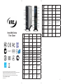
Ref English Français
Deutsch Español
Components Composants Bauteile Componentes
1 Power Button Bouton d’ali-
mentation
Ein/Aus-Taste Botón de encendido
2 Audio Out Port Port sortie
audio
Audioaus-
gang-Anschluss
Puerto de salida de
audio
3 Mic Microphone Mic Micrófono
4 Two USB Ports Deux ports
USB
Zwei USB-An-
schlüsse
Dos puertos USB
5 Link LED LED de liaison Link-LED LED enlace
6 HDD LED LED disque dur HDD-LED LED HDD
7 Smart Card
(Optional)
Carte à puce
(facultative)
Smart Card
(Option)
Smart Card
(Opcional)
8 Pedestal Piédestal Sockel Pedestal
9 LPT Port Port LPT LPT-Anschluss Puerto LPT
10 COM Port 3
(Optional)
Port COM 3
(facultatif)
COM-Anschluss
3 (Option)
Puerto COM 3
(opcional)
11, 12 COM Port 2, COM
Port 1
Port COM 2,
Port COM 1
COM-An-
schluss2,
COM-Anschluss1
Puerto COM 2,
puerto COM 1
13 Power Cord
Anchor
Fiche du
cordon d’ali-
mentation
Netzkabelver-
ankerung
Ancla del cable de
alimentación
14 Mini PCIe Wireless
LAN (Optional)
LAN sans l
min-PCle
(facultatif)
Mini PCIe
Wireless LAN
(Option)
Mini PCIe de
LAN inalámbrica
(opcional)
Front View Rear View
Ref English Français
Deutsch Español
Components Composants Bauteile Componentes
15 Ethernet Port Port ethernet Ethernet-An-
schluss
Puerto Ethernet
16 Four USB Ports Quatre ports
USB
Vier USB-An-
schlüsse
Cuatro puertos
USB
17 Display Port (DP) Port d’afchage
(DP)
Display-An-
schluss (DP)
Puerto de pantalla
(DP)
18 DVI-I Port (VGA
via DVI-I to VGA
Dongle)
Port DVI-I
(VGA à travers
DVI-I sur le
dongle VGA)
DVI-I Anschluss
(VGA über DVI-I
zu VGA Dongle)
Puerto DVI-I (VGA
mediante adaptador
DVI-I a VGA)
19 PS/2 Mouse Port Port souris
PS/2
PS/2 Maus-An-
schluss
Puerto de ratón
PS/2
20 PS/2 Keyboard
Port
Port clavier
PS/2
PS/2 Tastatur-An-
schluss
Puerto de teclado
PS/2
21 DC Power In Alimentation
d’entrée DC
DC Stromein-
gang
Entrada CC

Switching on the Itona Md Series
Press the Power Button. You will hear a beep and subsequently the
operating system start-up screen appears.
Reporting a Problem
1. Go to http://www.vxl.net/Support/Online-support.aspx
2. Select Click Here under the relevant support required.
3. In the Email Address eld, enter your email address.
4. Under Requests option, click Submit.
5. Fill in the requested information along with the problem
description, and click Save.
Your problem will be registered and you will receive an email with a
ticket number.
Please mention the ticket number in future correspondence
regarding the issue.
Checking the Status of Your Ticket
1. Go to http://www.vxl.net/Support/Online-support.aspx
2. Select Click Here under the relevant support required.
3. In the Email Address eld, enter your email address.
4. Click View Mine. Your request status will be displayed.
For more details about Product Warranty, please visit:
http://www.vxl.net/Support/Product-Warranty-Terms.aspx.
3
4
5
Français
Client Léger Itona Série Md
Guide d’Installation Hardware
Le paquet Itona Série Md est composé des articles listés ci-dessous:
• Client léger Itona Série Md
• Cordon d’alimentation (facultatif)
• Adaptateur d’alimentation 19 V DC
• DVI-I sur le dongle VGA (de type M)
• Piédestal
• Antenne externe (facultative)
• Souris (facultative)
• Ce manuel
Instructions de sécurité
Veuillez suivre ces précautions lorsque vous installez l’Itona série
Md:
• Utilisez un cordon d’alimentation homologué à 3 broches
mis à la terre. Assurez-vous de brancher le cordon d’ali
mentation sur une prise électrique à 3 broches mise à la
terre.
• Laissez une espace d’environ 10 cm autour du produit,
pour assurer une ventilation efcace.
• Positionnez toujours le client verticalement, pour assurer
un refroidissement par convection.
• N’utilisez pas cet équipement dans un environnement
corrosif ou explosif.
Installation de l’Itona Série Md
1. Retirez l’unité du carton. Veillez à ne pas faire tomber le
produit lorsque vous le retirez du carton : ceci pourrait
endommager le produit.
2. Enclenchez le piédestal pour positionner le client léger sur
un bureau,
ou
Installez la station VESA pour monter le client léger sur un
mur, derrière le moniteur ou sous un comptoir.
Note: Pour toutes informations complémentaires sur
l’in stallation de la station VESA et du piédestal,
veuillez vous reporter au Guide d’utilisation
hardware Itona Série Md.
3. Connectez la souris et le clavier à leurs ports PS/2
respectifs. Si vous utilisez un clavier USB ou une souris
USB, connectez-les aux ports USB.
4. Connectez les appareils série aux ports COM.
5. Connectez le câble réseau au port ethernet.
6. Connectez le cordon d’alimentation sur une prise élec
trique à 3 broches mise à la terre.
Itona Md Series Thin Client
Hardware Installation Guide
The Itona Md Series package consists of the items listed below:
• Itona Md Series Thin Client
• Power Cord (Optional)
• Power Adapter 19 V DC
• DVI-I to VGA Dongle (Type M)
• Pedestal
• External Antenna (Optional)
• Mouse (Optional)
• This Manual
Safety Instruction
Follow these precautions when installing Itona Md Series:
• Use approved 3 Pin grounded power cord only. Ensure
that you plug the power cord into a grounded 3 pin
electrical outlet.
• Allow approximately 4 Inches of space around the product
for effective ventilation.
• Always place the client vertically for convection cooling.
• Do not operate this equipment in corrosive or explosive
environment.
Setting up the Itona Md Series
1. Unpack the unit from the carton. Take care not
to drop the product when removing from the carton
as it may damage the product.
2. Snap t the pedestal to place the thin client on a desk.
Or
Install the VESA Dock to mount the thin client on a wall,
behind the monitor or under the counter.
Note: For more information about installing the
VESA Dock and Pedestal, refer to the
Itona Md Series Hardware User Guide.
3. Connect the mouse and keyboard to their respective PS/2
ports. If you are using a USB keyboard or mouse, connect
them to the USB ports.
4. Connect serial devices to the COM ports.
5. Connect the network cable to the Ethernet Port.
6. Connect the power cable to a grounded 3 pin electrical
outlet.
7. Connect the monitor to the Display Port,
DVI-I port or the VGA port (via DVI-I to VGA dongle).
Note: For instructions to connect dual monitors,
refer to the Itona Md Series Hardware User
Guide.
English

Itona Md Serie Thin Client
Hardware-Installationsanweisungen
Das Itona Paket der Md Serie besteht aus den folgenden Posten:
• Itona Md Serie Thin Client
• Netzkabel (Option)
• Netzgerät 19 V DC
• DVI-I zu VGA Dongle (Typ M)
• Sockel
• Externe Antenne (Option)
• Maus (Option)
• Diesem Handbuch
Sicherheitsanweisungen
Befolgen Sie diese Sicherheitsmaßnahmen bei der Installation von
Itona Md Serie Geräten:
• Stets ein zugelassenes dreistiftiges, geerdetes Netzkabel
benutzen. Das Netzkabel muss an eine geerdete, dreistif
tige Steckdose angeschlossen werden.
• Um das Produkt herum ca. 10cm Freiraum lassen, um
effektive Belüftung zu gewährleisten.
• Den Client zur Umluftkühlung stets vertikal aufstellen.
• Das Gerät darf nicht in einer korrosiven oder explosions
gefährdeten Umgebung betrieben werden.
Setup des Itona Md Serie
1. Die Einheit aus dem Karton nehmen. Das Produkt vor
sichtig herausnehmen und nicht fallen lassen, da es
dadurch beschädigt werden könnte.
2. Den Sockel aufschnappen, um den Thin Client auf einem
Schreibtisch aufzustellen
Oder
Das VESA Dock installieren, um den Thin Client an der
Wand, hinter dem Monitor oder unter der Arbeitsplatte
anzubringen.
Hinweis: Weitere Informationen zur Installation
von VESA Dock und Sockel nden Sie in den
Hardware-Benutzeran weisungen für die
Itona Md Serie.
3. Maus und Tastatur an die entsprechenden PS/2 An
schlüsse anschließen. Wenn Sie eine USB-Tastatur oder
-Maus benutzen, schließen Sie diese an die USB-An
schlüsse an.
4. Serielle Geräte an die COM-Anschlüsse anschließen.
5. Netzwerkkabel an den Ethernet-Anschluss anschließen.
6. Netzkabel an eine geerdete, dreistiftige Steckdose an
schließen.
Deutsch
6 7 8
7. Den Monitor an den Display-Anschluss, DVI-I-Anschluss
oder VGA-Anschluss anschließen (mit DVI-I zu
VGA Dongle).
Hinweis: Anweisungen für den Anschluss von zwei
Monitoren nden Sie in den Hardware-Benu
tzeranweisungen für die Itona Md Serie.
Einschalten des Itona der Md Serie
Den Ein/Aus-Schalter drücken. Sie hören einen Piepton, dann er-
scheint die Startanzeige des Betriebssystems.
Melden eines Problems
1. Gehen Sie zu
http://www.vxl.net/Support/Online-support.aspx
2. Wählen Sie Hier klicken unter der gewünschten Unter
stützungsart.
3. Geben Sie Ihre Emailadresse in dem Feld Email
adresse ein.
4. Klicken Sie unter der Anträge Option auf Senden.
5. Geben Sie die geforderten Informationen und die Bes
chreibung des Problems ein und klicken Sie dann auf
Speichern.
Ihr Problem wird nun registriert, und Sie werden ein Email mit einer
Ticketnummer erhalten.
Geben Sie diese Ticketnummer in Zukunft bitte in jeder Korrespon-
denz an, die sich auf dieses Problem bezieht.
Ticketstatus verfolgen
1. Gehen Sie auf
http://www.vxl.net/Support/Online-support.aspx
2. Wählen Sie Hier klicken unter der gewünschten Unter
stützungsart.
3. Geben Sie Ihre Emailadresse in dem Feld Emailadresse
ein.
4. Wenn Sie nun auf Meine betrachten klicken, erscheint der
Status Ihres Antrags.
Für weitere Einzelheiten über die Produktgarantie besuchen Sie
bitte:
http://www.vxl.net/Support/Product-Warranty-Terms.aspx.
7. Connectez le moniteur au port d’afchage, au port DVI-I
ou au port VGA (à travers DVI-I sur le dongle VGA).
Note : Pour toutes instructions sur la connexion de
deux moniteurs, veuillez vous reporter au Guide
d’utilisation hardware Itona Série Md.
Allumer l’Itona Série Md
Appuyez sur le bouton d’alimentation. Vous entendrez un bip, et
l’écran de démarrage du système d’exploitation sera ensuite afché.
Signaler un problème
1. Veuillez vous connecter sur :
http://www.vxl.net/Support/Online-support.aspx
2. Cliquez sur Click Here, dans la section de support
appropriée.
3. Dans le champ Email Address, veuillez inscrire votre
adresse e-mail.
4. Dans la section Requests, cliquez sur Submit.
5. Remplissez les informations nécessaires et la description
du problème, et cliquez sur Save.
Votre problème sera enregistré, et vous recevrez un e-mail avec un
numéro de billet.
Veuillez mentionner ce numéro de billet dans toute correspondance
concernant ce problème.
Vérier le statut de votre billet
1. Veuillez vous connecter sur :
http://www.vxl.net/Support/Online-support.aspx
2. Cliquez sur Click Here, dans la section de support
appropriée.
3. Dans le champ Email Address, veuillez inscrire votre
adresse e-mail.
4. Cliquez sur View Mine. Le statut de votre interrogation
sera alors afché.
Pour toutes informations complémentaires sur la garantie du
produit, veuillez visiter :
http://www.vxl.net/Support/Product-Warranty-Terms.aspx.
La page charge ...
-
 1
1
-
 2
2
-
 3
3
-
 4
4


Vxl Itona Md and Md+ Series Guide d'installation
- Taper
- Guide d'installation
dans d''autres langues
Documents connexes
-
Vxl Itona F and Fd Series Guide d'installation
-
-
-
-
-
-