Bosch NGM5456UC/01 Guide d'installation
- Catégorie
- Cuisinières
- Taper
- Guide d'installation

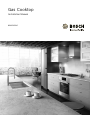
Installation Manual
Gas Cooktop
NGM5456UC

2
Table of Contents
Use and care manual
Safety Definitions .......................................................... 2
IMPORTANT SAFETY INSTRUCTIONS ........................ 3
Gas Appliance Safety .......................................................... 3
................................................................................................. 4
Propane Gas Installation ..................................................... 4
Equipment and Usage Safety Requirements .................. 4
Appliance Handling Safety ................................................. 4
Safety Codes and Standards ............................................. 5
State of California Proposition 65 Warning: .................... 5
Electric Safety ....................................................................... 5
High Altitude Installation ..................................................... 5
Before You Begin .......................................................... 6
Tools and Parts Needed ..................................................... 6
Parts Included ....................................................................... 6
General Information ............................................................. 6
Preparation ............................................................................ 6
Installation Procedure .................................................. 8
Prepare the Countertop ...................................................... 8
Seal the Cooktop with Foam Tape ................................... 8
Install the Cooktop ............................................................... 9
Connect Gas Supply ........................................................... 9
Connect Electrical Supply ............................................... 10
Burner Cap and Burner Base Placement ..................... 10
Install Burner Grates ......................................................... 12
Check the Installation ....................................................... 12
Service ......................................................................... 12
Before Calling Service ..................................................... 12
Safety Definitions
9 WARNING
This indicates that death or serious injuries may
occur as a result of non-observance of this warning.
9 CAUTION
This indicates that minor or moderate injuries may
occur as a result of non-observance of this warning.
NOTICE: This indicates that damage to the appliance or
property may occur as a result of non-compliance with
this advisory.
Note: This alerts you to important information and/or
tips.
4XHVWLRQV"
ZZZERVFKKRPHFRPXV
:HORRNIRUZDUGWRKHDULQJIURP\RX
7KLV%RVFK$SSOLDQFHLVPDGHE\
%6++RPH$SSOLDQFHV&RUSRUDWLRQ
0DLQ6WUHHW6XLWH
,UYLQH&$

3
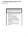
9 IMPORTANT SAFETY INSTRUCTIONS
READ AND SAVE THESE INSTRUCTIONS
IMPORTANT SAFET Y I NS T RUCT I ONS RE AD AND SAVE THESE INSTRUCTIONS
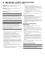
Gas Appliance Safety
²
'RQRWVWRUHRUXVHJDVROLQHRURWKHUIODPPDEOH
YDSRUVDQGOLTXLGVLQWKHYLFLQLW\RIWKLVRUDQ\
RWKHUDSSOLDQFH
²
:+$772'2,)<2860(//*$6
'RQRWWU\WROLJKWDQ\DSSOLDQFH
'RQRWWRXFKDQ\HOHFWULFDOVZLWFK
'RQRWXVHDQ\SKRQHLQ\RXUEXLOGLQJ
,PPHGLDWHO\FDOO\RXUJDVVXSSOLHUIURPD
QHLJKERU·VSKRQH)ROORZWKHJDVVXSSOLHU·V
LQVWUXFWLRQV
,I\RXFDQQRWUHDFK\RXUJDVVXSSOLHUFDOO
WKHILUHGHSDUWPHQW
²
,QVWDOODWLRQDQGVHUYLFHPXVWEHSHUIRUPHG
E\DTXDOLILHGLQVWDOOHUVHUYLFHDJHQF\RUWKH
JDVVXSSOLHU
:$51,1*,IWKHLQIRUPDWLRQLQWKHVHLQVWUXFWLRQV
LVQRWIROORZHGH[DFWO\DILUHRUH[SORVLRQPD\
UHVXOWFDXVLQJSURSHUW\GDPDJHSHUVRQDOLQMXU\
RUGHDWK

9 IMPORTANT SAFETY INSTRUCTIONS
READ AND SAVE THESE INSTRUCTIONS
4
IMPORTANT: SAVE THESE INSTRUCTIONS FOR THE
LOCAL ELECTRICAL INSPECTOR’S USE.
INSTALLER: LEAVE THESE INSTRUCTIONS WITH THE
UNIT FOR THE OWNER.
OWNER: PLEASE RETAIN THESE INSTRUCTIONS FOR
FUTURE REFERENCE.
WARNING
When properly cared for, your new appliance has been
designed to be safe and reliable. Read all instructions
carefully before use. These precautions will reduce the
risk of burns, electric shock, fire and injury to persons.
When using kitchen appliances, basic safety precautions
must be followed including those in the following pages.
WARNING
Do not repair, replace or remove any part of the
appliance unless specifically recommended in the
manuals. Improper installation, service or maintenance
can cause injury or property damage. Refer to this
manual for guidance. All other servicing must be done by
an authorized service agency.
▯ Install a gas shutoff valve near the appliance. It must
be easily accessible in an emergency.
▯ Leak testing must be conducted by the installer
according to the instructions in this manual.
▯ The appliance and its individual shutoff valve must be
disconnected from the gas supply piping system
during any pressure testing at pressures in excess of
1/2 psi (3.5 kPa).
▯ The appliance must be isolated from the gas supply
piping system by closing its individual manual shutoff
valve during any pressure testing of the gas supply
piping system at test pressures equal to or less than
1/2 psi (3.5 kPa).
▯ The minimum supply pressure must be 1” water
column above the manifold pressure printed on the
data plate.
▯ The maximum supply pressure must not exceed 14.0
inches water column (34.9 Millibars).
▯ For Massachusetts installations:
▯ Installation must be performed by a qualified or
licensed contractor, plumber or gas fitter qualified
or licensed by the state, province or region where
this appliance is being installed.
▯ Shut-off valve must be a “T” handle gas cock.
▯ Flexible gas connector must be new and not longer
than 36 inches.
▯ Installer-show the owner where the gas shut-off valve
is located.
Propane Gas Installation
▯ The propane gas tank must be equipped with its own
high pressure regulator. In addition, the regulator
supplied with this unit must also be used.
▯ The appliance is shipped from the factory for use with
natural gas. It must be converted for use with propane.
A qualified technician or installer must do the
conversion.
Equipment and Usage Safety
Requirements
▯ The cooktop must be used in conjunction with a
suitable ventilation system.
▯ Remove all tape and packaging before using the
appliance. Destroy the packaging after unpacking the
appliance. Never allow children to play with packaging
material.
▯ Never modify or alter the construction of the
appliance. For example, do not remove panels, wire
covers or screws.
▯ To eliminate the risk of burns or fire while reaching
over heated surface units, cabinet storage space
located above the surface units should be avoided. If
cabinet storage is to be provided, the risk can be
reduced by installing a hood that projects horizontally
a minimum of 5 inches beyond the bottom of the
cabinet.
▯ Verify that cabinets above the cooktop are a maximum
of 13 inches (330mm) deep.
Appliance Handling Safety
CAUTION
Hidden surfaces may have sharp edges. Use caution
when reaching behind or under appliance.

5
9 IMPORTANT SAFETY INSTRUCTIONS
READ AND SAVE THESE INSTRUCTIONS
Safety Codes and Standards
▯ This appliance complies with one or more of the
following standards:
ANSI Z21.1, Household Cooking Gas Appliances
▯ It is the responsibility of the owner and the installer to
determine if additional requirements and/or standards
apply to specific installations.
▯ Installation must conform with local codes or, in the
absence of local codes, with the National Fuel Gas
Code, ANSI Z223.1/NFPA 54 or, in Canada, the
Natural Gas and Propane Installation Code, CSA
B149.1.
▯ The appliance must be electrically grounded in
accordance with local codes or, in the absence of
local codes, with the National Electrical Code ANSI/
NFPA 70 or the Canadian Electric Code, CSA C22.1-
02.
State of California Proposition 65
Warning:
WARNING
This product can expose you to chemicals including vinyl
chloride, which is known to the State of California to
cause cancer and birth defects or other reproductive
harm. For more information go to
www.P65Warnings.ca.gov.
Note: IMPORTANT SAFETY NOTICE: The California Safe
Drinking and Toxic Enforcement Act requires the
Governor of California to publish a list of substances
known to the state to cause cancer, birth defect or other
reproductive harm, and requires businesses to warn
customers of potential exposure to such substances. The
burning of gas cooking fuel and the elimination of soil
during self-cleaning can generate small amounts of
carbon monoxide. The fiberglass insulation in Self Clean
ovens gives off very small amounts of formaldehyde
during the first several cleaning cycles. California lists
formaldehyde as a potential cause of cancer. Carbon
monoxide is a potential cause of reproductive toxicity.
Exposure to these substances can be minimized by:
1.
Providing good ventilation when cooking with gas.
2.
Operating the unit according to the instructions in this
manual.
Electric Safety
▯ Before you plug in an electrical cord, be sure all
controls are in the OFF position.
▯ For appliances equipped with a cord and plug, do not
cut or remove the ground prong. It must be plugged
into a matching grounding type receptacle to avoid
electrical shock. If there is any doubt as to whether the
wall receptacle is properly grounded, the customer
should have it checked by a certified electrician.
▯ This appliance should be installed in accordance with
the National Electric Code or Canadian Electrical
Code. It is required that the cooktop be installed on a
grounded, non-GFCI branch circuit.
▯ Installer-show the owner the location of the circuit
breaker or fuse. Mark it for easy reference.
▯ Before installing, turn power OFF at the service panel.
Lock service panel to prevent power from being turned
ON accidentally.
▯ Be sure your appliance is properly installed and
grounded by a certified technician. Installation,
electrical connections and grounding must comply
with all applicable codes.
High Altitude Installation
Contact customer service for use at altitudes above
2,000 feet (610 meters).

6
Before You Begin
Tools and Parts Needed
▯ Phillips Head Screwdriver
▯ Precision Flathead Screwdriver
▯ Tape Measure
▯ Teflon Tape (Gas Rated)
▯ Adjustable Wrench or Channel Lock Pliers
Parts Included
▯ Foam Tape
▯ Hold Down Brackets (4)
▯ Adjusting Screws, #10-32 x 2 1/2” (63.8 mm) (4)
▯ Sheet Metal Screws, #8 x 3/8” (9.5 mm) (4)
▯ Washers (4)
▯ Burner Grates (2)
▯ Burners (4)
▯ Burner Caps (4)
▯ Pressure Regulator
▯ LP Gas Conversion Kit
Note: If parts are missing or damaged, call the number
or write to the address listed on the inside back cover.
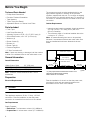
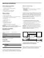
General Information
Overall Dimensions
Note: These are overall dimensions NOT cutout
dimensions.
Preparation
Electrical Requirements
9 CAUTION
Do not use an extension cord with the gas cooktop.
This appliance requires a 60 Hz, 15 Amp, 120 VAC
connection. Plan the installation so that the power
connection is accessible from the front of the cabinet.
Gas Requirements
Supply Pressure:
▯ Natural Gas: 7 inches water column (14.9 Millibars)
▯ Propane Gas:11 inches water column (27.4 Millibars)
The propane gas tank must be equipped with its own
high pressure regulator in addition to the pressure
regulator supplied with this unit. The cooktop is shipped
from the factory for use with natural gas. For use with LP
conversion, a certified technician or installer must do the
conversion.
Cabinet Requirements
▯ Instructions are based on standard American cabinets
36” high (91cm) x 24” deep (61cm) with a 25”
(63cm) countertop.
▯ The maximum depth of a cabinet installed above the
cooktop is 13” (33cm).
Note: All measurements given have to be precisely
followed. If nonstandard cabinets are used, make sure
they are installed with minimum dimensions shown
below.
Plan the installation of the unit so that the power cord,
gas shut-off valve and gas pressure regulator are
accessible from the front of the cabinet.
Width (Side to Side) 23” (582 mm)
Depth (Front to Back) 20.5” (520 mm)
Height (Top to Bottom) 3.75” (95 mm)
min.
18" (460)
min. 3" (76)
A
bove counter - min. 30" (762) to
Combustible surface
min. 24" (610)
Depth from back wall
Cabinet max. 13" (330)
Left side
*
4" (102) required when installed with a built-in oven.
Reference the Bosch Under Cooktop
Built-in Guide for more details.
Centered over cooktop
Rear wall - 2" (51)
*min. 3" (76)
Right side
( )=mm

7
Countertop Requirements
Notes
▯ All measurements given must be precisely followed. If
nonstandard cabinets are used, make sure they are
installed with minimum dimensions shown below.
▯ When installed in combination with a hood, refer to
hood manufacturer’s requirements for installation.
Island Installation
Notes
▯ All measurements given have to be precisely followed.
If nonstandard cabinets are used, make sure they are
installed with minimum dimensions shown in image
below.
▯ 2 1/8” denotes front of cooktop.
Mounting Requirements
Use the hold down brackets supplied. See “Install the
Cooktop” section for further details.
Ventilation Requirements
We strongly recommend the installation of ventilation with
the appliance. The appliance must be installed according
to the furnished instructions.
9 CAUTION
The appliance should not be installed with a
ventilation system that blows air downward toward
the burners. This type of ventilation system may
cause ignition and combustion problems with the
gas cooking appliance resulting in personal injury or
unintended operation.
max.3"
(max. 76)
gas
connection
* 5
1
/
16
"
required when installed with a built-in oven.
Reference the Bosch Under Cooktop
Built-in Guide for more details.
min. 3"
(min. 76)
( )=mm
20
1
/
2
"
(520)
19
1
/
4
"
(487)
1
3
/
4
"
(45)
20
7
/
8
"
(529)
1"
(25)
23"
(582)
1" (25)
2
3
/
4
"
(70)
3
1
/
16
"
(78)
*3
1
/
16
"
(78)
2 1/8
"
(54)
3
"
(76.2)
3
"
(76.2)
3 1/8"
(79.4)
( )=mm

8
Installation Procedure
Prepare the Countertop
9 WARNING
To avoid electrical shock hazard, before installing
the cooktop, switch power off at the service panel to
prevent the power from being switched on
accidentally.
Cut out the countertop per the dimensions shown in the
section “Cabinet Requirements”.
Some solid surface materials require different cutting
methods. Consult with the solid surface manufacturer for
the correct cutting method needed. Apply heat reflective
tape such as Scotch Aluminum Foil Tape #425 or #427
(not included) around the cutout so that it folds over the
top and sides. Do not wrap the tape underneath the
cooktop. Be sure the tape extends beyond the outermost
flange of the cooktop. All corners should be covered with
tape.
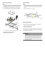
Solid Surface Countertops-Counter Cutout
Seal the Cooktop with Foam Tape
Note: Failure to install the foam tape may affect burner
performance.
Apply the self adhesive foam tape in one continuous
rectangle directly to the counter around the perimeter of
the cutout as shown by the dotted line in the image
below. The foam tape should be flush with the edge of
the cutout.
Foam Tape Placement-Counter Cutout
$
A Heat Reflective Tape
A Foam Tape Placement
$

9
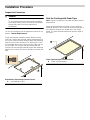
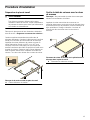
Install the Cooktop
Insert the cooktop into the cutout. Attach the clamps of
the mounting brackets packaged with the cooktop. Use
the washer and screws provided.
Adjust the mounting brackets to desired position and
tighten screws to cooktop. Insert adjusting screw into
clamp and secure cooktop to countertop.
Attaching Mounting Brackets
Note: For solid surface material installations:
▯ Insert a wooden block between the end of the screw
and the bottom of the countertop.
▯ Do not overtighten adjusting screw.
▯ Trim excess aluminum tape around cooktop flange.
Tip: Install hold down bracket without the adjusting
screw installed. Turn hold down brackets flush with the
sides of the cutout. This will help with inserting cooktop in
hard-to-reach spaces.
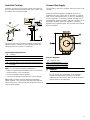
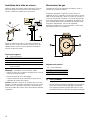
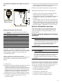
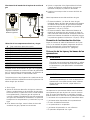
Connect Gas Supply
The gas inlet to the unit is located at the right rear of the
cooktop.
Install the pressure regulator (supplied with unit) to
manifold pipe using Teflon tape on threads of manifold
pipe. Turn to hand tighten plus 1/4 turn, not exceeding 1
turn for alignment. To prevent possible damage to the
gas pressure regulator, install it after the cooktop is in its
permanent position. When the regulator is securely
installed on the manifold pipe, the conversion nut will be
easily accessible.
Pressure Regulator
9 WARNING
Do not attempt any adjustment of the pressure
regulator, except when converting to propane.
Adjustments could lead to leaks or cause incorrect
gas pressure to the appliance.
A Cooktop
B/H Hold Down Bracket
C/E Adjusting Screw
D Foam Tape (Seal)
G Wooden Block (to be used with solid surfacing
material)
$
%
*
(
+
'
&
A Manifold Pipe
B Conversion Nut
C Pressure Regulator
$
%&

10
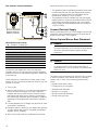
Side View Gas Cooktop Installation
Gas and Electrical Location
Connect the gas supply line to the unit pressure
regulator using a 1/2” flex gas line connector between
manual shut-off valve and pressure regulator. Always use
a new flex line.
Check supply line connections for leaks using a soap
solution or non-corrosive leak detection fluid. Do not use
a flame of any sort.
1.
Turn on gas.
2.
Apply a soap solution or non-corrosive leak detection
fluid to all joints and fittings in the gas connection
between the shut-off valve and the cooktop. Include
gas fittings and joints in the cooktop if connections
may have been disturbed during installation. Bubbles
appearing around fittings and connections indicate a
leak.
3.
If a leak appears, turn off supply line gas shut-off valve
and tighten connections.
4.
Retest for leaks by turning on the supply line gas shut-
off valve. When leak check is complete (no bubbles
appear), test is complete.
5.
Wipe off all soap solution or detection fluid residue.
Important Notes for Gas Connection:
▯ The appliance and its individual gas shutoff valve must
be disconnected from the gas supply piping system
during any pressure testing of that system at test
pressures in excess of 1/2 psi (3.5kPa).
▯ The appliance must be isolated from the gas supply
piping system by closing its individual manual shut-off
valve during any pressure testing of the gas supply
piping system at test pressures equal to or less than
1/2 psi (3.5kPa).
Connect Electrical Supply
Before connecting the 5-foot (1.5m) supply cord to a wall
receptacle, make certain that gas shut-off valve and all
burner controls are in OFF position.
Burner Cap and Burner Base Placement
9 WARNING
To prevent flare-ups, do not use the cooktop without
all burner caps and all burner grates properly
positioned.
9 WARNING
To prevent burns, do not touch burner caps or
grates while hot. Turn the cooktop off and allow the
burners to cool.
The burner caps must be properly placed for the cooktop
to function properly. If the burner cap is not properly
placed, one or more of the following problems may
occur:
▯ Burner flames are too high.
▯ Flames shoot out of burners.
▯ Stainless steel discolors.
▯ Burners do not ignite.
▯ Burner flames light unevenly.
▯ Burner emits gas odor.
A Rough-in Cooktop Box
B Arrow on Pressure Regulator
C Pressure Regulator
D 1/2” Female Pipe Threads
E Flexible Gas Line
G Power Cord (60 inches/1,524mm)
H 120 Volt Receptacle
J Gas Cut-off Valve
K Gas Supply Line Stub-out
L Floor
Arrow on the pressure
regulator shows the
direction of gas flow
%
$
%
&
(
'
*
+
-
/
.

11
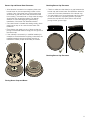
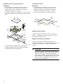
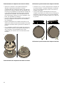
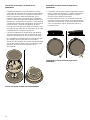
Burner Cap and Burner Base Placement
▯ After electrical connection is complete, place each
burner base on the corresponding location on the
cooktop. One of the three bars on the burner base
should line up with the notch and prevent the base
from rotating. The small hole or cutout near the edge
should also line up with the igniter. Pay special
attention to avoid damaging the igniter during
installation of the base. See Illustration below.
▯ Once each base is located and resting evenly, place
each burner cap on its correct burner base. See
Illustration.
▯ Place burner cap gently on top of base so that the
prongs of the burner base fit snugly into the groove of
the burner cap.
▯ If the maintop is removed by a certified installer (for
example to check electrical or piping connection) the
panhead screws that were removed must be re-
installed to ensure proper functionality of burners.
Placing Burner Caps and Bases
Checking Burner Cap Placement
▯ Check to make sure that there is no gap between the
burner cap and burner base. See illustration below for
correct and incorrect placements of the burner cap.
▯ You may gently try to move the burner cap from side
to side to check if it is properly placed. If properly
placed, the cap will click from side to side as the
prongs hit the groove ridge.
Checking Burner Cap Placement
1
2

12
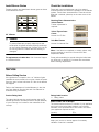
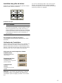
Install Burner Grates
Properly position and install each burner grate as shown
in the illustration below.
24” 4 Burner
9 WARNING
To prevent flare-ups, properly support pots and
avoid spills, all grates must be properly positioned
on the cooktop whenever the cooktop is in use. Do
not use a grate if the rubber feet are missing or
damaged.
For replacement of rubber feet: Call Customer Support
at 1-800-944-2904.
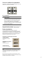
Check the Installation
Place each correct sized burner cap in its seated,
notched position and check the operation of the electric
igniters. Check flame characteristics. Flame should be
blue with a minimal yellow tip on the outer cone of the
flames.
Checking Flame Characteristics
Note: If the flame is completely or mostly yellow, verify
that the regulator is set for the correct fuel. After
adjustment, retest.
Some yellow streaking is normal during the initial start-
up. Allow unit to operate 4-5 minutes and re-evaluate
before making adjustments.
Service
Before Calling Service
If the igniters do not spark or the “on” indicator lights
(available in some models) do not glow, check the power
source to see if a fuse has blown or if the circuit breaker
has tripped.
Refer to the Statement of Limited Warranty in the Use
and Care Manual. See the Use and Care Manual for
troubleshooting information.
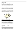
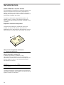
Product Rating Label
The rating label shows the model number and the FD
number (production number/product’s unique identifier)
of your cooktop. It is located on the underside of the
cooktop.
Rating Label Location
Model number and FD Number
The model number and the FD number of your appliance
are found on the rating label. Make a note of these
numbers in the space below to save time in the event
your appliance requires service.
Keep your invoice or escrow papers for warranty
validation if service is needed.
Yellow Flames:
Further adjustment is
required.
Yellow Tips on Outer
Cones:
Normal for LP Gas
Soft Blue Flames:
Normal for Natural Gas
A Rating Label
Model # FD #
Bosch Customer Support 800-944-2904
$

13
Table des Matières
Notice d’uti li sati on
Définitions de sécurité ................................................ 13
IMPORTANTES CONSIGNES DE SÉCURITÉ ............. 14
Utilisation sécuritaire de l'électroménager alimenté au
gaz : ..................................................................................... 14
.............................................................................................. 15
Installation au gaz propane ............................................. 15
Exigences en matière de sécurité pour l'utilisation et
l'équipement ....................................................................... 15
Sécurité de manutention des appareils ........................ 16
Codes et normes de sécurité ......................................... 16
Avertissement issue de la proposition 65 de l’État de la
Californie : ........................................................................... 16
Sécurité électrique ............................................................ 16
Installation à altitude élevée ............................................ 16
Avant de commencer .................................................. 17
Outils et pièces nécessaires ........................................... 17
Pièces incluses .................................................................. 17
Informations générales .................................................... 17
Préparatifs .......................................................................... 17
Procédure d'installation ............................................. 19
Préparation du plan de travail ........................................ 19
Sceller la table de cuisson avec le ruban de mousse 19
Installation de la table de cuisson ................................. 20
Branchement du gaz ........................................................ 20
Brancher l'alimentation électrique .................................. 21
Positionnement du chapeau et de la base du brûleur 21
Installation des grilles du brûleur ................................... 23
Vérification de l'installation .............................................. 23
Dépannage ................................................................... 24
Avant d'appeler le service de dépannage ................... 24
Définitions de sécurité
9 AVERTISSEMENT
Ceci indique que le non-respect de cet
avertissement peut entraîner des blessures graves,
voire la mort.
9 ATTENTION
Ceci indique que le non-respect de cet
avertissement peut entraîner des blessures légères
ou de gravité moyenne.
AVIS : Ceci indique que la non-conformité à cet avis de
sécurité peut entraîner des dégâts matériels ou
endommager l'appareil.
Remarque : Ceci vous signale des informations et/ou
indications importantes.
9RXVDYH]GHVTXHVWLRQV"
ZZZERVFKKRPHFRPXV
ââ
1RXVQRXVIHURQVXQSODLVLUGHYRXVVHUYLU
&HWDSSDUHLOpOHFWURPpQDJHU%RVFKHVWIDEULTXpSDU
%6++RPH$SSOLDQFHV&RUSRUDWLRQ
0DLQ6WUHHW6XLWH
,UYLQH&$

9 IMPORTANTES CONSIGNES DE SÉCURITÉ
LIRE ET CONSERVER CES INSTRUCTIONS
14
IMPORTANTES CONSI GNES DE S ÉCURI T É LI RE ET CONSE RV E R CE S INSTRUCTIONS
Utilisation sécuritaire de l'électroménager alimenté au gaz :
²
1HSDVFRQVHUYHURXXWLOLVHUGHOHVVHQFHRX
GDXWUHVOLTXLGHVRXYDSHXUVLQIODPPDEOHVj
SUR[LPLWpGHFHWDSSDUHLORXGHWRXWDXWUHDSSDUHLO
²
48()$,5(6,92863(5&(9(=81(2'(85'(*$=
1HSDVHVVD\HUGHPHWWUHXQDSSDUHLOVRXVWHQVLRQ
1HSDVWRXFKHUGLQWHUUXSWHXUGHFRXUDQWpOHFWULTXH
1HSDVXWLOLVHUGHWpOpSKRQHVGDQVOpGLILFH
&RPPXQLTXHULPPpGLDWHPHQWDYHFOHIRXUQLVVHXU
GHJD]GHSXLVODSSDUHLOWpOpSKRQLTXHGXQYRLVLQ
5HVSHFWHUOHVGLUHFWLYHVGXIRXUQLVVHXUGHJD]
6LOVDYqUHLPSRVVLEOHGHMRLQGUHOHIRXUQLVVHXUGH
JD]FRPPXQLTXHUDYHFOHVSRPSLHUV
²
8WLOLVHUOHVVHUYLFHVGXQLQVWDOODWHXURXGXQHDJHQFH
GHVHUYLFHVTXDOLILpVRXOHIRXUQLVVHXUGHJD]SRXU
SURFpGHUjOLQVWDOODWLRQHWDX[UpSDUDWLRQV
$9(57,66(0(176LOHVGLUHFWLYHVQHVRQWSDV
VXLYLHVjODOHWWUHLO\DXQULVTXHGLQFHQGLHRX
GH[SORVLRQSRXYDQWHQWUDvQHUGHVGRPPDJHV
PDWpULDX[GHVEOHVVXUHVRXXQGpFqV

15
9 IMPORTANTES CONSIGNES DE SÉCURITÉ
LIRE ET CONSERVER CES INSTRUCTIONS
IMPORTANT : CONSERVEZ CES CONSIGNES À
L'INTENTION DE L'INSPECTEUR EN ÉLECTRICITÉ.
INSTALLATEUR : PRIÈRE DE LAISSER CES
CONSIGNES AVEC CET APPAREIL À L'INTENTION DU
PROPRIÉTAIRE.
PROPRIÉTAIRE : PRIÈRE DE CONSERVER CES
CONSIGNES POUR RÉFÉRENCE ULTÉRIEURE.
AVERTISSEMENT
Correctement entretenu, votre électroménager neuf a été
conçu pour être sécuritaire et fiable. Lisez attentivement
toutes les instructions avant l’utilisation. Ces précautions
réduiront le risque de brûlure, d'électrocution, d’incendie
et de blessures corporelles. Lorsque vous utilisez des
appareils électroménagers de cuisine, il importe de
suivre des précautions de sécurité de base, y compris
celles indiquées dans les pages suivantes.
AVERTISSEMENT
Ne pas réparer, remplacer ni retirer toute pièce de
l’électroménager à moins que cela ne soit
spécifiquement recommandé par les manuels.
L'installation, l'entretien ou une réparation inadéquat
pourrait causer des blessures ou des dégâts matériels.
Consulter ce manuel pour les directives d'utilisation.
Toute autre réparation doit être effectuée par une agence
de service d'entretien autorisé.
▯ Installer un robinet d'arrêt près de l'électroménager. Il
doit être facilement accessible en cas d'urgence.
▯ L'installateur doit procéder au test de fuites selon les
consignes fournies dans le présent manuel.
▯ L'appareil et son propre robinet d'arrêt doivent être
déconnectés de la canalisation du système
d'alimentation en gaz au cours de test aux pressions
qui dépassent 1/2 PSI (3,5 kPa).
▯ L’électroménager doit être isolé de la canalisation du
système d'alimentation en gaz en fermant son propre
robinet d'arrêt manuel pour tout test de pression à des
pressions égales ou inférieures à 1/2 PSI (3,5 kPa).
▯ La pression d'admission minimum doit être de 1 po de
colonne d'eau au-dessus de la pression d'admission
imprimée sur la plaque signalétique.
▯ La pression d'admission maximum ne doit pas
excéder 14 po de colonne d'eau (34,5 millibars).
▯ Pour les installations au Massachusetts :
▯ L'installation doit être exécutée par un entrepreneur,
un plombier ou un ajusteur d'appareils à gaz
qualifié ou autorisé par l'État, la province ou la
région d'installation de cet électroménager.
▯ Le robinet d'arrêt doit être robinet à gaz avec
poignée en T.
▯ Le connecteur à gaz souple doit être neuf et ne doit
pas dépasser 36 pouces.
▯ Installateur : prière d'indiquer au propriétaire,
l'emplacement du robinet d'arrêt.
Installation au gaz propane
▯ Le réservoir de gaz propane doit être doté de son
propre régulateur de pression élevée. De plus, le
régulateur de pression livré avec cet appareil doit
aussi être utilisé.
▯ L'électroménager est livré de l'usine prêt à utiliser avec
du gaz naturel. Il doit être converti pour usage avec
gaz propane. Un technicien ou un installateur qualifié
doit procéder à la conversion.
Exigences en matière de sécurité pour
l'utilisation et l'équipement
▯ Utiliser un système de ventilation convenable avec la
table de cuisson.
▯ Retirer tout le ruban adhésif et l'emballage avant
d'utiliser l'électroménager. Jeter l'emballage après
avoir déballé l'électroménager. Ne jamais laisser les
enfants jouer avec le matériel d'emballage.
▯ Ne jamais altérer ni modifier la configuration de
l'électroménager. Par exemple, ne pas retirer les
panneaux, les couvre-fils ou les vis.
▯ Pour éliminer le risque de brûlure ou d'incendie
lorsque vous vous étirez au-dessus des surfaces
chauffantes de l'électroménager, il faut éviter d'installer
des armoires de rangement au-dessus de la surface
de l'électroménager. Si une armoire de rangement est
installé, il est possible de réduire le risque en installant
une hotte qui dépasse (horizontalement) d'au moins
5 po le bord du fond de l'armoire.
▯ Vérifier que la profondeur des armoires au-dessus de
la table de cuisson est au maximum de 13 po
(330 m).

9 IMPORTANTES CONSIGNES DE SÉCURITÉ
LIRE ET CONSERVER CES INSTRUCTIONS
16
Sécurité de manutention des appareils
ATTENTION
Des parties cachées pourraient avoir des rebords
tranchants. Redoubler de vigilance quand vous passez la
main derrière ou sous l'électroménager.
Codes et normes de sécurité
▯ Cet appareil est conforme à une ou plusieurs des
normes suivantes :
ANSI Z21.1, Appareils électroménagers pour la
cuisson à gaz
▯ Il incombe au propriétaire et à l'installateur de
déterminer si des exigences et/ou normes
additionnelles s'appliquent pour des installations
spécifiques.
▯ L’installation doit être conforme aux codes locaux ou,
en l’absence de tels codes, au National Fuel Gas
Code ANSI Z223.1/NFPA 54 ou, au Canada, au code
national CSA B149.1 d’installation du gaz naturel et
du propane.
▯ L'électroménager doit être mis à la terre en conformité
aux codes locaux, ou en l’absence de tels codes, au
National Electric Code ANSI/NFPA 70 ou, au Canada,
au code canadien de l’électricité CSA C22.1-02.
Avertissement issue de la proposition 65
de l’État de la Californie :
AVERTISSEMENT
Ce produit peut vous exposer à des produits chimiques,
comme du chlorure de vinyle, reconnus par l’État de la
Californie comme causant le cancer, des malformations
congénitales ou d’autres effets nocifs sur la
reproduction. Pour de plus amples renseignements,
consultez www.P65Warnings.ca.gov.
Remarque : AVIS DE SÉCURITÉ IMPORTANT : En
application de la loi californienne concernant la salubrité
de l’eau et la protection contre les substances chimiques
(« California Safe Drinking Water and Toxic Enforcement
Act »), le gouverneur de Californie est tenu de publier
une liste reconnue par l’État de Californie comme étant
cancérigènes ou pouvant causer des malformations ou
présenter un danger pour la reproduction, et les
entreprises sont tenues d’avertir les consommateurs des
risques potentiels d’exposition à de telles substances. La
combustion de gaz combustible pour la cuisson et
l'élimination de résidus pendant l'autonettoyage peuvent
générer de faibles quantités de monoxyde de carbone.
Dans les fours équipés du Nettoyage Auto, de faibles
quantités de formaldéhyde peuvent se dégager lors de
l'élimination des salissures pendant les quelques
premiers cycles autonettoyants. La Californie classe le
formaldéhyde parmi les produits potentiellement
cancérigènes. Le monoxyde de carbone est une cause
possible de toxicité pour la reproduction. Il est possible
de réduire l'exposition à ces substances en :
1.
assurant une bonne ventilation lors de la cuisson au
gaz; et
2.
utilisant l'appareil selon les instructions de ce manuel.
Sécurité électrique
▯ Avant de brancher le cordon électrique, vérifier que
toutes les commandes sont à la position OFF (Arrêt).
▯ Pour les électroménagers dotés d'un cordon
d'alimentation avec fiche, ne pas couper ni enlever la
broche de mise à la terre. Pour éviter toute
électrocution, brancher le cordon dans une prise de
courant correspondante avec mise à la terre. En cas
de doute concernant la mise à la terre appropriée de
la prise murale, le client doit faire vérifier celle-ci par
un électricien qualifié.
▯ Cet électroménager doit être installé conformément au
Code national de l'électricité ou au Code canadien de
l'électricité. L'installation de la table de cuisson doit
être sur un circuit mis à la terre sans disjoncteur
différentiel de fuite à la terre (non-DDFT).
▯ Installateur : Indiquez au propriétaire l'emplacement
du disjoncteur ou du fusible. Identifiez sa position pour
pouvoir le retrouver facilement.
▯ Avant l'installation, couper l'alimentation au panneau
de service. Verrouiller le panneau de service pour
empêcher que l'alimentation ne soit rétablie par
accident.
▯ S'assurer que l’électroménager est correctement
installé et mis à la terre par un technicien qualifié.
L’installation, les raccordements électriques et la mise
à la terre doivent être conformes avec tous les codes
applicables.
Installation à altitude élevée
Communiquer avec le service après-vente pour une
utilisation au-dessus de 2 000 pi (610 mètres).

17
Avant de commencer
Outils et pièces nécessaires
▯ Tournevis à tête Phillips
▯ Tournevis à lame plate de précision
▯ Ruban à mesurer
▯ Ruban de teflon (de classe Gaz)
▯ Clé réglage ou pince multiprise
Pièces incluses
▯ Ruban de mousse
▯ Supports de fixation (4)
▯ Vis de réglage, No 10-32 x 2 1/2 po (63,8 mm) (4)
▯ Vis à tôle, No 8 x 3/8 po (9,5 mm) (4)
▯ Rondelles (4)
▯ Grilles de brûleur (2)
▯ Brûleurs (4)
▯ Chapeaux de brûleur (4)
▯ Régulateur de pression
▯ Trousse de conversion au gaz de PL
Remarque : Si des pièces sont manquantes ou
endommagées, composer le numéro indiqué ou écrire à
l'adresse indiquée à la troisième de couverture.
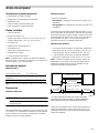
Informations générales
Dimension hors tout
Remarque : Ce sont les dimensions hors tout et NON
les dimensions pour la découpe.
Préparatifs
Exigences électriques
9 ATTENTION
Ne pas utiliser une rallonge avec la table de
cuisson.
Cet électroménager a besoin d'un raccord de 60 Hz,
15 A, 120 volts c.a. Planifier l'installation de sorte que le
raccord électrique est accessible de l'avant de l'armoire.
Exigences en matière de gaz
Pression d'admission :
▯ Gaz naturel : 7 po de colonne d'eau (14,9 millibars)
▯ Gaz propane : 11 po de colonne d'eau
(27,4 millibars)
Le réservoir de gaz propane doit être doté de son propre
régulateur de pression élevée en plus du régulateur de
pression fourni avec cet appareil. Cette table de cuisson
est livrée de l'usine prête à utiliser avec du gaz naturel.
Pour une conversion au gaz de PL, un technicien ou un
installateur qualifié doit y procéder.
Exigences concernant les armoires
▯ Les consignes sont fondées sur des armoires
normales (aux États-Unis) de 36 po (91 cm) de
hauteur et de 24 po (61 cm) de profondeur avec un
plan de travail de 25 po (63 cm).
▯ La profondeur maximale de l'armoire installée au-
dessus de la table de cuisson est de 13 po (33 cm).
Remarque : Il faut respecter précisément toutes les
mesures fournies. Dans le cas d'armoires hors normes,
s'assurer qu'elles ont les dimensions minimales
d'installation indiquées ci-dessous.
Planifier l'installation de l'appareil de sorte que le cordon
d'alimentation, le robinet d'arrêt et le régulateur de
pression sont accessibles de l'avant de l'armoire.
Largeur (d'un côté à
l'autre)
23 po (582 mm)
Profondeur (de l'avant
vers l'arrière)
20.5 po (520 mm)
Hauteur (du haut au bas) 3,75 po (95 mm)
mín.
*
( )=mm
Profondeur depuis le mur arrière
armoire max. 13 po (330)
Au-dessus du comptoir - min. 30 po (762) à
surface combustible
Côté gauche
mur arrière - 2 po (51)
Centrée au-dessus
de la table de cuisson
Côté droit
4 po (102) nécessaire si installée avec un four encastré.
la table de cuisson pour plus de renseignements.
Consulter le guide Bosch du four encastré sous
min. 24 po (610)
min. 3 po (76)
18 po (460)
*min. 3 po (76)

18
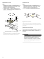
Exigences concernant le plan de travail
Remarques
▯ Il faut respecter précisément toutes les mesures
fournies. Dans le cas d'armoires hors normes,
s'assurer qu'elles ont les dimensions minimales
d'installation indiquées ci-dessous.
▯ Lors d'une installation en combinaison avec une hotte,
consulter les exigences d'installation du fabricant de la
hotte.
Installation sur un îlot
Remarques
▯ Il faut respecter précisément toutes les mesures
fournies. Dans le cas d'armoires hors normes,
s'assurer qu'elles ont les dimensions minimales
d'installation indiquées sur l'image ci-dessous.
▯ 2 1/8 po indique l'avant de la table de cuisson.
Exigences pour la fixation
Utiliser les supports de fixation fournis. Consulter la
section « Installation de la table de cuisson » pour de
plus amples renseignements.
Exigences concernant la ventilation
Nous recommandons fortement l'installation d'un
système de ventilation avec l'électroménager. Il doit être
installé conformément aux consignes d'installation
fournies.
9 ATTENTION
L'électroménager ne doit pas être installé avec un
système de ventilation qui souffle l'air vers le bas en
direction des brûleurs. Ce type de système de
ventilation peut entraîner des problèmes d'allumage
et de combustion avec l'appareil de cuisson au gaz
pouvant causer des blessures corporelles ou un
fonctionnement indésirable.
(max. 76)
* 5
1
/
16
(min. 76)
20
1
/
2
(520)
19
1
/
4
(487)
1
3
/
4
(45)
20
7
/
8
(529)
1
(25)
23
(582)
2
3
/
4
(70)
3
1
/
16
(78)
*3
1
/
16
(78)
Consulter le guide Bosch du four encastré sous la table
de cuisson pour plus de renseignements.
max. 3 po
po
po
po
po
po
min. 3 po
po
po
po
1 po (25)
po
raccord
de gaz
( ) = mm
po nécessaire si installée avec un four encastré.
2 1/8
"
(54)
3"
(76.2)
3"
(76.2)
3 1/8"
(79.4)
( )=mm

19
Procédure d'installation
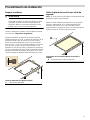
Préparation du plan de travail
9 AVERTISSEMENT
Pour éviter tout danger d'électrocution avant
d'installer la table de cuisson, couper l'alimentation
au panneau de service pour éviter que l'alimentation
soit rétablie accidentellement.
Découper le plan de travail aux dimensions indiquées
dans la section « Exigences concernant les armoires ».
Certains matériaux demandent des méthodes de
découpe différentes. Consulter le fabricant de la surface
solide pour connaître la bonne méthode de découpe.
Appliquer du ruban réflecteur de chaleur comme du
ruban d'aluminium Scotch no 425 ou no 427 (non
compris) autour de la découpe pour qu'il se plie par
dessus la surface et les côtés. Ne pas plier le ruban sous
la table de cuisson. S'assurer que le ruban dépasse au-
delà du rebord externe de la collerette de la table de
cuisson. Tous les coins doivent être couverts de ruban.
Découpe de la surface solide du plan de travail
Sceller la table de cuisson avec le ruban
de mousse
Remarque : Ne pas installer le ruban de mousse peut
influencer le rendement du brûleur.
Appliquer le ruban autocollant de mousse en un
rectangle ininterrompu sur le rebord de la découpe dans
le plan de travail (sur le périmètre) comme illustré par la
ligne pointillée sur l'image ci-dessous. Le ruban de
mousse doit être de niveau avec le rebord de la
découpe.
Placement du ruban de mousse sur le périmètre de la
découpe dans le plan de travail
A Ruban réflecteur de chaleur
$
A Placement du ruban de mousse
$

20
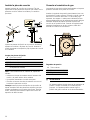
Installation de la table de cuisson
Insérer la table de cuisson dans la découpe. Fixer les
pinces du support de fixation livré avec la table de
cuisson. Utiliser la rondelle et les vis fournis.
Régler le support de fixation à la hauteur désirée, et
serrer les vis à la table de cuisson. Insérer les vis de
réglage dans la pince et fixer solidement la table de
cuisson au plan de travail.
Fixation des supports
Remarque : Installation sur une surface solide :
▯ Insérer un bloc de bois entre l'extrémité de la vis et le
dessous du plan de travail.
▯ Ne pas trop serrer la vis de réglage.
▯ Couper l'excès de ruban d'aluminium autour de la
collerette de la table de cuisson.
Conseil : Installer le support de retenue sans la vis de
réglage. Tourner le support de retenue pour qu'il soit de
niveau avec les côtés de la découpe. Cela aidera à la
pose de la table des cuisson dans des espaces difficiles
à atteindre.
Branchement du gaz
L'admission de gaz de l'appareil est située à droite, à
l'arrière de la table de cuisson.
Installer le régulateur de pression (fourni avec cet
appareil) au tuyau collecteur avec du ruban teflon sur les
filets du tuyau collecteur. Serrer à la main en tournant 1/
4 de tour de plus sans excéder 1 tour pour l'alignement.
Pour éviter d'endommager le régulateur de pression de
gaz, l'installer après avoir mis la table de cuisson dans
sa position permanente. Une fois le régulateur
solidement installé sur le tuyau collecteur, il sera facile
d'accéder à l'écrou de conversion.
Régulateur de pression
9 AVERTISSEMENT
Ne pas essayer d'ajuster le régulateur de pression à
moins de convertir l'électroménager au propane.
Les réglages peuvent entraîner des fuites ou une
mauvaise pression en direction de l'électroménager.
A Table de cuisson
B/H Support de retenue
C/E Vis de réglage
D Ruban de mousse (scellé)
G Bloc de bois (à utiliser avec le matériau de la
surface solide)
$
%
*
(
+
'
&
A Tuyau collecteur
B Écrou de conversion
C Régulateur de pression
$
%&
La page charge ...
La page charge ...
La page charge ...
La page charge ...
La page charge ...
La page charge ...
La page charge ...
La page charge ...
La page charge ...
La page charge ...
La page charge ...
La page charge ...
La page charge ...
La page charge ...
La page charge ...
La page charge ...
La page charge ...
La page charge ...
La page charge ...
La page charge ...
-
 1
1
-
 2
2
-
 3
3
-
 4
4
-
 5
5
-
 6
6
-
 7
7
-
 8
8
-
 9
9
-
 10
10
-
 11
11
-
 12
12
-
 13
13
-
 14
14
-
 15
15
-
 16
16
-
 17
17
-
 18
18
-
 19
19
-
 20
20
-
 21
21
-
 22
22
-
 23
23
-
 24
24
-
 25
25
-
 26
26
-
 27
27
-
 28
28
-
 29
29
-
 30
30
-
 31
31
-
 32
32
-
 33
33
-
 34
34
-
 35
35
-
 36
36
-
 37
37
-
 38
38
-
 39
39
-
 40
40


Bosch NGM5456UC/01 Guide d'installation
- Catégorie
- Cuisinières
- Taper
- Guide d'installation
dans d''autres langues
- English: Bosch NGM5456UC/01 Installation guide
- español: Bosch NGM5456UC/01 Guía de instalación
- português: Bosch NGM5456UC/01 Guia de instalação
Documents connexes
-
Bosch NGM8046UC Guide d'installation
-
Bosch NGM3450UC Guide d'installation
-
Bosch NGM3051UC Manuel utilisateur
-
-
-
-
Bosch NGM8657UC Le manuel du propriétaire
-
Bosch NGMP077UC Manuel utilisateur
-