Daikin FTXB12AXVJU Guide d'installation
- Catégorie
- Climatiseurs split-system
- Taper
- Guide d'installation
Ce manuel convient également à

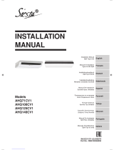
INSTALLATION
MANUAL
R410A SPLIT SERIES
IM-5WMYJ(R)-0617(0)-DAIKIN USA
Part Number.: R08019046594
MODELS
FTXB09A RXB09A
FTXB12A RXB12A
FTXB18A RXB18A
FTXB24A RXB24A
FTKB09A RKB09A
FTKB12A RKB12A
FTKB18A RKB18A
FTKB24A RKB24A
Installation Manual
R410A Split Series
Manuel d’installation
Série split R410A
Manual de instalación
Serie Split R410A
English
Français
Español
CVR IM-5WMYJ(R)-0617(0)-DAIKIN U1 1CVR IM-5WMYJ(R)-0617(0)-DAIKIN U1 1 10/12/17 10:30:39 AM10/12/17 10:30:39 AM

CVR IM-5WMYJ(R)-0617(0)-DAIKIN U2 2CVR IM-5WMYJ(R)-0617(0)-DAIKIN U2 2 10/12/17 10:30:39 AM10/12/17 10:30:39 AM

English
1-1
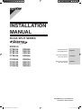
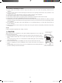
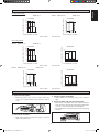
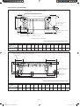
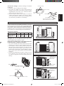
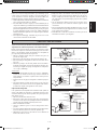
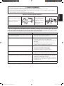
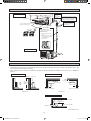
Indoor Unit [FTXB/FTKB]
A
B
FRONT VIEW
TOP VIEW
C
SIDE VIEW
B
THE MARK SHOWS PIPING DIRECTION
REAR REAR
RIGHTLEFT
BOTTOM
BOTTOM
FRONT GRILLE FIXED SCREWS
(INSIDE)
LOUVER
SIGNAL RECEIVER
INDOOR UNIT
ON/OFF SWITCH
ROOM TEMPERATURE THERMISTOR
(INSIDE)
NAME PLATE
TERMINAL
BLOCK
WITH EARTH
TERMINAL
OUTLINE AND DIMENSIONS
Original Instruction
1 IM-5WMYJ(R)-0617(0)-DAIKIN USA1 11 IM-5WMYJ(R)-0617(0)-DAIKIN USA1 1 10/12/17 10:30:57 AM10/12/17 10:30:57 AM

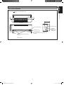
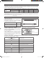
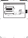
1-2
Dimension
Model
ABCDEFGHIJKLM
09/12 35-1/16
(890)
11-11/16
(297)
8-1/4
(210)
4-1/16
(104)
5-9/16
(141)
1-3/16
(30)
1-13/16
(46)
2-3/16
(55)
2-3/16
(56)
6
(153)
7-1/8
(181)
8-1/8
(207)
2-1/16
(52)
All dimensions are in Inch (mm)
D
B
G
H
J
L
M
A
K
F
I
GF
E
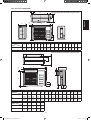
Through the wall hole
Ø
2-9/16" (65mm)
Drain hose position
Liquid pipe end
Gas pipe end
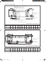
INSTALLATION PLATE 18/24
«
Recommended mounting plate retention spots
(7 spots in all)
All dimensions are in Inch (mm)
«
Recommended mounting plate retention spots
(5 spots in all)
Through the wall hole
Ø
2-9/16" (65mm)
Drain hose position
Gas pipe end
Liquid pipe end
E
F
G
IK
ML
JH
G
F
B
D
A
INSTALLATION PLATE 09/12
Indoor Unit [FTXB/FTKB]
Dimension
Model
ABCDE FGH I JK L M
18/24 46-1/8
(1172)
12-5/8
(320)
9-1/2
(242)
7-1/2
(190)
6-13/16
(173)
2-3/8
(61)
1-9/16
(40)
1-3/4
(45)
1-7/8
(48)
3-9/16
(91)
8-5/8
(219)
22-13/16
(580)
1-3/4
(45)
1 IM-5WMYJ(R)-0617(0)-DAIKIN USA2 21 IM-5WMYJ(R)-0617(0)-DAIKIN USA2 2 10/12/17 10:30:58 AM10/12/17 10:30:58 AM

English
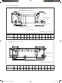
1-3
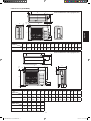
Outdoor Unit [RXB/RKB]
Dimension
Model
ABCDEFGHIJKLMNO
18 33-11/16
(855)
24-3/4
(628)
12-15/16
(328)
20-1/2
(520)
7-1/16
(179)
1-13/16
(46)
4
(101)
4-7/16
(113)
23-3/4
(603)
4-15/16
(126)
6-7/16
(164)
9/16
(15)
1-5/16
(34)
15/16
(23)
14-1/4
(362)
24 33-11/16
(855)
28-3/4
(730)
12-15/16
(328)
20-1/2
(520)
7-1/16
(179)
1-13/16
(46)
4
(101)
4-7/16
(113)
23-3/4
(603)
4-15/16
(126)
6-7/16
(164)
9/16
(15)
1-5/16
(34)
15/16
(23)
14-1/4
(362)
Dimension
Model
ABCDEFGHIJKLMNOPQ
09/12 21-5/8
(550)
25-15/16
(658)
2
(51)
7/16
(11)
10-3/4
(273)
5/8
(16)
9/16
(14)
18-1/2
(470)
3-3/4
(96)
3-11/16
(93)
3-11/16
(94)
2-3/8
(60)
9/16
(14)
5-1/4
(133)
5/16
(8)
3/8
(10)
11-3/4
(299)
Dimension
Model
PQRST
18 2-7/8
(73)
2-15/16
(75)
5/16
(8)
2-5/8
(67)
1/4
(7)
24 2-7/8
(73)
2-15/16
(75)
5/16
(8)
2-5/8
(67)
1/4
(7)
EF
B
HI
N
Q
KL
G
A
M
CD
J
5/64
(2)
OP
B
A
O
N
P
Q
DM
IJJ
K
L
FE
C
GH
L
S
R
T
All dimensions are in Inch (mm)
All dimensions are in Inch (mm)
1/8
(3)
1 IM-5WMYJ(R)-0617(0)-DAIKIN USA3 31 IM-5WMYJ(R)-0617(0)-DAIKIN USA3 3 10/12/17 10:30:58 AM10/12/17 10:30:58 AM

1-4
! WARNING ! CAUTION
Only qualified personnel must carry out the installation
work. Installation must be done in accordance with this
installation manual. Improper installation may result in water
leakage, electric shock, or fire.
When installing the unit in a small room, take measures to
keep the refrigerant concentration from exceeding allowable
safety limits. Excessive refrigerant leaks, in the event of
an accident in a closed ambient space, can lead to oxygen
deficiency.
Use only specified accessories and parts for installation
work. Failure to use specified parts may result in water
leakage, electric shock, fire, or the unit falling.
Install the air conditioner or heat pump on a foundation
strong enough to withstand the weight of the unit. A
foundation of insufficient strength may result in the unit
falling and causing injuries.
Take into account strong winds, typhoons, or earthquakes
when installing. Improper installation may result in the unit
falling and causing accidents.
Make sure that a separate power supply circuit is provided for
this unit and that all electrical work is carried out by qualified
personnel according to local, state, and national regulations.
An insufficient power supply capacity or improper electrical
construction may lead to electric shock or fire.
Make sure that all wiring is secured, that specified wires
are used, and that no external forces act on the terminal
connections or wires. Improper connections or installation
may result in fire.
When wiring, position the wires so that the electrical wiring
box cover can be securely fastened. Improper positioning of
the electrical wiring box cover may result in electric shock,
fire, or the terminals overheating.
Before touching electrical parts, turn off the unit.
It is recommended to install a ground fault circuit interrupter
if one is not already available. This helps prevent electric
shock or fire.
Securely fasten the outdoor unit terminal cover (panel). If the
terminal cover/panel is not installed properly, dust or water
may enter the outdoor unit causing fire or electric shock.
When installing or relocating the system, keep the refrigerant
circuit free from substances other than the specified
refrigerant (R410A) such as air. Any presence of air or other
foreign substance in the refrigerant circuit can cause an
abnormal pressure rise or rupture, resulting in injury.
Do not change the setting of the protection devices. If the
pressure switch, thermal switch, or other protection device
is shorted and operated forcibly, or parts other than those
specified by Daikin are used, fire or explosion may occur.
•
•
•
•
•
•
•
•
•
•
•
•
•
Do not touch the switch with wet fingers. Touching a switch
with wet fingers can cause electric shock.
Do not allow children to play on or around the unit to
prevent injury.
The heat exchanger fins are sharp enough to cut. To avoid
injury wear gloves or cover the fins while working around
them.
Do not touch the refrigerant pipes during and immediately
after operation as the refrigerant pipes may be hot or cold,
depending on the condition of the refrigerant flowing through
the refrigerant piping, compressor, and other refrigerant
cycle parts. Your hands may suffer burns or frostbite if you
touch the refrigerant pipes. To avoid injury, give the pipes
time to return to normal temperature or, if you must touch
them, be sure to wear proper gloves.
Install drain piping to proper drainage. Improper drain piping
may result in water leakage and property damage.
Insulate piping to prevent condensation.
Be careful when transporting the product.
Do not turn off the power immediately after stopping
operation. Always wait for at least 5 minutes before turning
off the power. Otherwise, water leakage may occur.
Do not use a charging cylinder. Using a charging cylinder
may cause the refrigerant to deteriorate.
Refrigerant R410A in the system must be kept clean, dry,
and tight.
(a) Clean and Dry -- Foreign materials (including mineral
oils such as SUNISO oil or moisture) should be
prevented from getting into the system
(b) Tight -- R410A does not contain any chlorine, does not
destroy the ozone layer, and does not reduce the earth’s
protection again harmful ultraviolet radiation. R410A
can contribute to the greenhouse effect if it is released.
Therefore, take proper measures to check for the
tightness of the refrigerant piping installation. Read the
chapter Refrigerant Piping and follow the procedures.
Since R410A is a blend, the required additional refrigerant
must be charged in its liquid state. If the refrigerant is charged
in a state of gas, its composition can change and the system
will not work properly.
The indoor unit is for R410A. See the catalog for indoor
models that can be connected. Normal operation is not
possible when connected to other units.
•
•
•
•
•
•
•
•
•
•
•
•
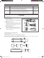
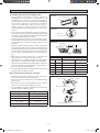
SAFETY PRECAUTIONS
INSTALLATION MANUAL
This manual provides the procedures of installation to ensure a safe and good standard of operation for the air conditioner unit.
Special adjustment may be necessary to suit local requirement.
Before using your air conditioner, please read this instruction manual carefully and keep it for future reference.
This appliance is intended to be used by expert or trained users in shops, in light industry and on farms, or for commercial use by lay
persons.
This appliance is not intended for use by persons, including children, with reduced physical, sensory or mental capabilities, or lack of
experience and knowledge, unless they have been given supervision or instruction concerning use of the appliance by a person responsible
for their safety.
Children should be supervised to ensure that they do not play with the appliance.
1 IM-5WMYJ(R)-0617(0)-DAIKIN USA4 41 IM-5WMYJ(R)-0617(0)-DAIKIN USA4 4 10/12/17 10:30:59 AM10/12/17 10:30:59 AM

English
1-5
Remote controller (wireless kit) transmitting distance can be
shorter than expected in rooms with electronic fluorescent
lamps (inverter or rapid start types). Install the indoor unit
far away from fluorescent lamps as much as possible.
Indoor units are for indoor installation only. Outdoor units
can be installed either outdoors or indoors. This unit is for
indoor use.
Do not install the air conditioner or heat pump in the
following locations:
(a) Where a mineral oil mist or oil spray or vapor is
produced, for example, in a kitchen. Plastic parts may
deteriorate and fall off or result in water leakage.
(b) Where corrosive gas, such as sulfurous acid gas, is
produced. Corroding copper pipes or soldered parts
may result in refrigerant leakage.
(c) Near machinery emitting electromagnetic waves.
Electromagnetic waves may disturb the operation of
the control system and cause the unit to malfunction.
(d) Where flammable gas may leak, where there is carbon
fiber, or ignitable dust suspension in the air, or where
volatile flammables such as thinner or gasoline are
handled. Operating the unit in such conditions can cause
a fire.
Take adequate measures to prevent the outdoor unit from
being used as a shelter by small animals. Small animals
making contact with electrical parts can cause malfunctions,
smoke, or fire. Instruct the user to keep the area around the
unit clean.
•
•
•
•
! DANGER
Refrigerant gas is heavier than air and replaces oxygen. A
massive leak can lead to oxygen depletion, especially in
basements, and an asphyxiation hazard could occur leading
to serious injury or death.
Do not ground units to water pipes, gas pipes, telephone
wires, or lightning rods as incomplete grounding can cause
a severe shock hazard resulting in severe injury or death.
Additionally, grounding to gas pipes could cause a gas leak
and potential explosion causing severe injury or death.
If refrigerant gas leaks during installation, ventilate the
area immediately. Refrigerant gas may produce toxic gas if
it comes into contact with fire. Exposure to this gas could
cause severe injury or death.
After completing the installation work, check that the
refrigerant gas does not leak throughout the system.
Do not install unit in an area where flammable materials
are present due to risk of explosions that can cause serious
injury or death.
Safely dispose all packing and transportation materials
in accordance with federal/state/local laws or ordinances.
Packing materials such as nails and other metal or wood parts,
including plastic packing materials used for transportation
may cause injuries or death by suffocation.
•
•
•
•
•
•
! NOTE
Install the power supply and inter-unit wires for the indoor
and outdoor units at least 3.5ft away from televisions or
radios to prevent image interference or noise. Depending
on the radio waves, a distance of 3.5ft may not be sufficient
to eliminate the noise.
Dismantling the unit, treatment of the refrigerant, oil and
additional parts must be done in accordance with the relevant
local, state, and national regulations.
Do not use the following tools that are used with conventional
refrigerants: gauge manifold, charge hose, gas leak detector,
reverse flow check valve, refrigerant charge base, vacuum
gauge, or refrigerant recovery equipment.
If the conventional refrigerant and refrigerator oil are mixed
in R410A, the refrigerant may deteriorate.
This air conditioner or heat pump is an appliance that should
not be accessible to the general public.
As design pressure is 536 psi, the wall thickness field-
installed pipes should be selected in accordance with the
relevant local, state, and national regulations.
•
•
•
•
•
•
NOTICE
Disposal requirements
Your air conditioning product is marked with this symbol. This means that electrical and electronic products shall not be mixed with
unsorted household waste.
Do not try to dismantle the system yourself: the dismantling of the air conditioning system, treatment of the refrigerant, of oil and of
other parts must be done by a qualifi ed installer in accordance with relevant local and national legislation.
Air conditioners must be treated at a specialized treatment facility for re-use, recycling and recovery. By ensuring this product is
disposed of correctly, you will help to prevent potential negative consequences for the environment and human health. Please contact
the installer or local authority for more information.
Batteries must be removed from the remote controller and disposed of separately in accordance with relevant local and national
legislation.
1 IM-5WMYJ(R)-0617(0)-DAIKIN USA5 51 IM-5WMYJ(R)-0617(0)-DAIKIN USA5 5 10/12/17 10:30:59 AM10/12/17 10:30:59 AM

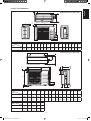
1-6
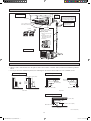
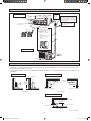
INSTALLATION DIAGRAM
Indoor Unit
Air filter
M4 x 12L
Front panel
2-3/16" (55mm) or more from ceiling
Outdoor Unit
1-15/16" (50mm) or more
from walls (on both sides)
Caulk pipe
hole gap
with putty.
Cut thermal insulation pipe to an
appropriate length and wrap it with
tape, making sure that no gap is left
in the insulation pipe’s cut line.
Wrap the insulation pipe
with the finishing tape
from bottom to top.
Service lid
19-11/16" (500mm) from wall
n Opening service lid
Service lid is removeable.
n Opening method
1) Remove the service lid
screws.
2) Pull out the service lid
diagonally down in the
direction of the arrow.
3) Pull down.
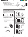
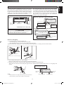
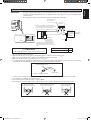
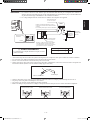
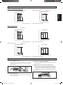
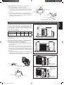
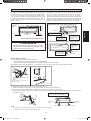
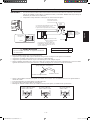
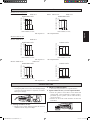
INSTALLATION OF THE OUTDOOR UNIT (09/12)
Where a wall or other obstacle is in the path of outdoor unit’s intake or exhaust airflow, follow the installation guidelines
below.
For any of the below installation patterns, the wall height on the exhaust side should be 47-1/4" (1200mm) or less.
•
•
Wall facing two sides
More than 1-15/16 (50)
Wall facing one side
More than 3-15/16 (100)
More than 1-15/16 (50) More than 1-15/16 (50)
Top View
Side View
More than
3-15/16 (100)
More than
5-7/8 (150)
More than 5-15/16 (150)
More than 11-13/16 (300)
More than 1-15/16 (50)
Unit : Inch (mm)
47-1/4
(1200)
or less
Wall facing three sides
Top View
1 IM-5WMYJ(R)-0617(0)-DAIKIN USA6 61 IM-5WMYJ(R)-0617(0)-DAIKIN USA6 6 10/12/17 10:30:59 AM10/12/17 10:30:59 AM

English
1-7
Return air
Service access
C
D
Obstacle
Obstacle
Return air
Discharge air
A
Obstacle
Obstacle
B
H/2
H
The outdoor unit must be installed in such a way, so as to prevent
short circuit of the hot discharged air or obstruction to the
smooth air flow. Please follow the installation clearances shown
in the figure. Select the coolest possible place where intake air
temperature is not greater than the outside air temperature (Refer
to operating range).
Installation clearances
Note: If there is any obstacle higher than half, of the unit’s
height (H), please allow more space than the figure indicated in
the above table.
Dimension
ABCD
Minimum Distance,
Inch (mm)
11-13/16
(300)
39-3/8
(1000)
11-13/16
(300)
19-11/16
(500)
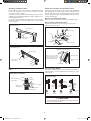
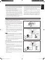
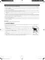
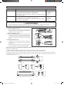
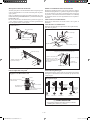
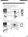
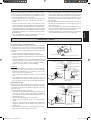
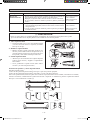
Condensed Water Disposal Of Outdoor Unit
(Heat Pump Unit Only)
There are 10 holes on the base of Outdoor Unit for condensed
water to flow out. Insert the drain elbow to one of the holes.
To install the drain elbow, first insert one portion of the hook to
the base (portion A), then pull the drain elbow in the direction
shown by the arrow while inserting the other portion to the
base. After installation, check to ensure that the drain elbow
clings to base firmly.
If the unit is installed in a snowy and chilly area, condensed
water may freeze in the base. In such case, please remove plug
at the bottom of unit to smooth the drainage.
•
•
•
Drain work. (Heat Pump Unit Only)
1) Use drain elbow for drainage.
2) If the drain port is covered by a mounting base or floor
surface, place additional foot bases of at least 1-3/16"
(30mm) in height under the outdoor unit’s feet.
3) In cold areas, do not use a drain elbow, drain plugs and a
drain hose with the outdoor unit. (Otherwise, drain water
may freeze, impairing heating performance.)
Bottom frame
Drain Elbow
Hose (available commercially,
inner dia. 5/8" (16mm))
INSTALLATION OF THE OUTDOOR UNIT (18/24)
Please remove
side plate when
connecting
the piping and
connecting cord
PUSH & PULL UP
BASE
A
DRAIN ELBOW
DRAIN ELBOW
Please remove
side plate when
connecting
the piping and
connecting cord
PUSH & PULL UP
09/12
18/24
Drain plug
Drain plug
Drain plug
Drain plug
Air outlet side
Air outlet side
Drain elbow
Drain elbow
1 IM-5WMYJ(R)-0617(0)-DAIKIN USA7 71 IM-5WMYJ(R)-0617(0)-DAIKIN USA7 7 10/12/17 10:31:00 AM10/12/17 10:31:00 AM

1-8
INSTALLATION OF THE OUTDOOR UNIT
1. Precautions for Selecting a Location
Choose a place solid enough to bear the weight and vibration of the unit, where the operating sound will not be
amplified.
Choose a location where the hot air discharged from the unit or the operating sound will not cause a nuisance to the
neighbors of the user.
Avoid locations, such as near bedrooms, where the operating sound may cause disturbance.
There must be sufficient space to carry the unit into and out of the site.
There must be sufficient space for air passage and no obstructions around the air inlet and the air outlet.
The site must not be prone to flammable gas leaks in the surrounding area.
Install units, power cords and inter-unit wire at least 10ft (3m) away from television and radio sets. (This is to prevent
interference to images and sounds. Noise may be produced even if they are more than 10ft (3m) away depending on radio
wave conditions.)
In coastal areas or other places with a salty atmosphere or one containing sulfate gas, corrosion may shorten the life of
the air conditioner.
Since water will flow from the drain of the outdoor unit, do not place under the unit anything which must be kept away
from moisture.
NOTE
Cannot be installed suspended from a ceiling or stacked.
! CAUTION
When operating the air conditioner in a low outdoor ambient temperature, be sure to follow the
instructions described below.
To prevent exposure to wind, install the outdoor unit with its suction side facing the wall.
Never install the outdoor unit at a site where the suction side may be exposed directly to
wind.
To prevent exposure to wind, it is recommended to install a baffle plate on the air discharge
side of the outdoor unit.
In heavy snow areas, select an installation site where the snow will not affect the unit.
If there is a likelihood of snow accumulating on the outdoor unit, attach a snow protection
hood.
In high humidity areas or heavy snow areas, it is recommended to attach a drain pan heater to
prevent ice build-up from the bottom frame.
1)
2)
3)
4)
5)
6)
7)
8)
9)
•
•
•
•
•
•
Install the unit high enough off the
ground to prevent burying in snow
Construct a large canopy.
Construct a pedestal.
•
•
1 IM-5WMYJ(R)-0617(0)-DAIKIN USA8 81 IM-5WMYJ(R)-0617(0)-DAIKIN USA8 8 10/12/17 10:31:01 AM10/12/17 10:31:01 AM

English
1-9
The indoor unit must be installed in such a way so as to prevent
short circuit of the cool discharged air with the hot return air.
Please follow the installation clearance shown in the figure. Do
not place the indoor unit where there could be direct sunlight
shining on it. Also, this location must be suitable for piping
and drainage, and be away from doors or windows.
min. 2" (50)
(Space for
maintenance)
Air flow
(Indoor)
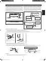
The refrigerant piping can be routed to the unit in a number
of ways (left or right from the back of the unit), by using the
cut-out holes on the casing of the unit. Bend the pipes carefully
to the required position in order to align it with the holes. For
the side and bottom out, hold the bottom of the piping and
then position it to the required direction. The condensation
drain hose can be taped to the pipes.
Right-side, right-back or right-bottom piping
min. 2-3/16" (55)
(Space for
performance)
Required space
Right-back piping
All dimensions are in Inch (mm)
Right-bottom
piping
Right-side piping
Remove pipe port cover
here for right-side piping
Left-back piping
Left-side piping
Left-bottom piping
Left-side, left-back or left-bottom piping
INSTALLATION OF THE INDOOR UNIT
Remove pipe port cover here
for right-bottom piping
Bind coolant pipe
and drain hose
together with
insulating tape.
Remove pipe port cover
here for left-side piping
Remove pipe port cover here
for left-bottom piping
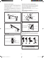
Bottom or side piping
Cut off pipe port cover with a copping saw.
For bottom piping: On the bottom of the front grille
For side piping: On the side cover (front grille side and unit side)
Apply the blade of the copping saw to the notch, and cut off the pipe port cover along the uneven inner surface.
1)
ü
ü
After cutting off the pipe cover, perform filing.
Remove the burrs along the cut section using a half round needle file.
Wrap the inter-unit wire, refrigerant pipes and drain hose together with insulation tape.
Then, insert the drain hose and refrigerant pipes into the wall hole after inserting them into the cut out piping hole
opened.
2)
3)
NOTE
Be careful not to let chips enter the driving section of the arm.
Be careful not to put pressure on the lower front panel.
ü
ü
Left-side
piping
Right-bottom piping
Right-side
piping
Bind refrigerant pipe and drain hose
together with adhesive vinyl tape.
Left-bottom piping
The figure shows the case of left bottom piping
Front grille side
Side cover
(front grille side)
min. 2" (50)
(Space for
maintenance)
! CAUTION
• Must be mounted with the lowest moving parts at
least 8ft (2.4m) above floor or grade level.
1 IM-5WMYJ(R)-0617(0)-DAIKIN USA9 91 IM-5WMYJ(R)-0617(0)-DAIKIN USA9 9 10/12/17 10:31:01 AM10/12/17 10:31:01 AM

1-10
Mounting Installation Plate
Ensure that the wall is strong enough to withstand the weight
of the unit. Otherwise, it is necessary to reinforce the wall
with plates, beams or pillars.
Use the level gauge for horizontal mounting, and fix it with 5
suitable screws for FTXB/FTKB 09/12 and 7 suitable screws
for FTXB/FTKB 18/24.
In case the rear piping draws out, drill a hole 2-9/16" (65mm)
in diameter with a cone drill, slightly lower on the outside
wall (see figure).
Water Drainage Piping
The indoor drain pipe must be in a downward gradient for
smooth drainage. Avoid situations that are likely to cause
water to leak.
Water
leaking
Water
retention
End
dipped
into
water
Drain
Correct Wrong
Water
leaking
Water
leaking
Wrong Wrong
Water Drainage
Mount The Unit Onto The Installation Plate
Hook the indoor unit onto the upper portion of the installation
plate (Engage the two hooks at the rear top of the indoor unit
with the upper edge of the installation plate). Ensure that the
hooks are properly seated on the installation plate by moving
it to the left and right.
How To Attach The Indoor Unit
Hook the claws of the bottom frame to the mounting plate.
How To Remove The Indoor Unit
Push up the marked area (at the lower part of the front
grille) to release the claws.
Mounting plate
Mounting plate
fixing screw
FTXB/FTKB 18/24
When stripping the ends
of interconnecting wires in
advance, bind right ends of
wires with insulating tape.
Hand indoor unit’s hook here.
Mounting plate
Interconnecting
wires
Wire guide
! CAUTION
• Do not install the unit at altitude over 6560ft (2000m)
for both indoor & outdoor.
Hole With Cone Drill
Inside
Ø
2-9/16" (65mm)
Wall embedded pipe
(Field supply)
Wall hole cover
(Field supply)
Wall embedded pipe
(Field supply)
Outside
Caulking
Drilling a Wall Hole and Installing Wall Embedded
Pipe
Mounting plate
Clip
Bottom frame
Mark (Rear side)
Front grille
Mounting plate
Mounting plate
fixing screw
FTXB/FTKB 09/12
1 IM-5WMYJ(R)-0617(0)-DAIKIN USA10 101 IM-5WMYJ(R)-0617(0)-DAIKIN USA10 10 10/12/17 10:31:01 AM10/12/17 10:31:01 AM

English
1-11
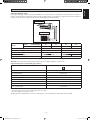
*Be sure to add the proper amount of additional refrigerant. Failure to do so may result in reduced performance.
Remark: The refrigerant pre-charged in the outdoor unit is for piping length up to 25ft (7.6m).
Allowable Piping Length
If the pipe is too long, both the capacity and reliability of the unit will drop. As the number of bends increases, resistance to
the flow of refrigerant system increases, thus lowering cooling capacity. As a result, the compressor may become defective.
Always choose the shortest path and follow the recommendations as tabulated below:
REFRIGERANT PIPING
Model
Indoor (FTXB/FTKB) 09 12 18 24
Outdoor (RXB/RKB) 09 12 18 24
Min. Allowable Length (L), ft/(m) 9.84' (3) 9.84' (3)
Max. Allowable Length (L), ft/(m) 65.6' (20) 98.4' (30)
Max. Allowable Elevation (E), ft/(m) 32.8' (10) 32.8' (10)
Gas Pipe Size, in/(mm)
3/8" (9.52) 1/2" (12.70) 5/8" (15.88)
Liquid Pipe Size, in/(mm)
1/4" (6.35) 1/4" (6.35)
Equivalent length for various fitting [Feet (meter)]
Pipe Size L joint
3/8" (OD9.52mm) 0.59' (0.18)
1/2" (OD12.7mm) 0.66' (0.20)
5/8" (OD15.9mm) 0.82' (0.25)
3/4" (OD19.1mm) 1.15' (0.35)
7/8" (OD22.2mm) 1.31' (0.40)
1" (OD25.4mm) 1.48' (0.45)
1 1/8" (OD28.6mm) 1.64' (0.50)
1 3/8" (OD34.9mm) 1.97' (0.60)
Notes:
1. Equivalent piping length is obtained with actual length of gas piping.
2. 90° bend of piping is equivalent to L joint.
Outdoor Unit
L E
Indoor Unit
Bending must be carefully made so as not to crush the pipe. Use a pipe bender to bend a pipe where possible.
1 IM-5WMYJ(R)-0617(0)-DAIKIN USA11 111 IM-5WMYJ(R)-0617(0)-DAIKIN USA11 11 10/12/17 10:31:01 AM10/12/17 10:31:01 AM

1-12
Piping Works And Flaring Technique
Do not use contaminated or damaged copper tubing. If
any piping, evaporator or condenser had been exposed or
had been opened for 15 seconds or more, the system must
be vacuumed. Generally do not remove plastic, rubber
plugs and brass nuts from the valves, fittings, tubing and
coils until it is ready to connect suction or liquid line into
valves or fittings.
If any brazing work is required, ensure that nitrogen gas
is passed through coil and joints while the brazing work
is being done. This will eliminate soot formation on the
inside wall of copper tubings.
Cut the pipe stages by stages, advancing the blade of pipe
cutter slowly. Extra force and a deep cut will cause more
distortion of pipe and therefore extra burr. See Figure I.
Remove burrs from cut edges of the pipes with remover. See
Figure II. Hold the pipe on top position and burr remover
at lower position to prevent metal chips from entering the
pipe. This will avoid unevenness on the flare faces which
will cause gas leak.
Insert the flare nuts, mounted on the connection parts
of both the indoor unit and outdoor unit, into the copper
pipes.
The exact length of pipe protruding from the top surface
of the swaging block is determined by the flaring tool.
See Figure III.
Fix the pipe firmly on the swaging block. Match the centers
of both the swaging block and the flaring punch, then
tighten the flaring punch fully.
The refrigerant pipe connection are insulated by closed
cell polyurethane.
Piping Connection To The Units
Align the center of the piping and tighten the flare nut
sufficiently with fingers. See Figure IV.
Finally, tighten the flare nut with torque wrench until the
wrench clicks.
When tightening the flare nut with the torque wrench,
ensure that the tightening direction follows the arrow
indicated on the wrench.
The refrigerant pipe connection are insulated by closed
cell polyurethane.
•
•
•
•
•
•
•
•
•
•
•
•
1/4t
Cutting Copper Tube
Copper Tube
Swaging Block
Remove Burr
Figure I
D
A
Pipe Size, in (mm) Torque, ft-lb (Nm)
1/4" (6.35) 13.3 (18)
3/8" (9.52) 31.0 (42)
1/2" (12.70) 40.6 (55)
5/8" (15.88) 48.0 (65)
3/4" (19.05) 57.6 (78)
Flared Tube
Flare Joint
Flare NutIndoor Piping
Torque Wrench
Spanner
Ø
Tube, D A (Inch/mm)
Inch mm Imperial
(Wing-nut Type)
Rigid
(Clutch Type)
1/4" 6.35 0.051" (1.3) 0.028" (0.7)
3/8" 9.52 0.063" (1.6) 0.039" (1.0)
1/2" 12.70 0.075" (1.9) 0.051" (1.3)
5/8" 15.88 0.087" (2.2) 0.067" (1.7)
3/4" 19.05 0.098" (2.5) 0.079" (2.0)
REFRIGERANT PIPING
Figure II
Figure III
Figure IV
1 IM-5WMYJ(R)-0617(0)-DAIKIN USA12 121 IM-5WMYJ(R)-0617(0)-DAIKIN USA12 12 10/12/17 10:31:01 AM10/12/17 10:31:01 AM

English
1-13
ELECTRICAL WIRING CONNECTION
IMPORTANT : * The figures shown in the table are for information purpose only. They should be checked and selected
to comply with the local/national codes of regulations. This is also subject to the type of installation and
conductors used.
** The appropriate voltage range should be checked with label data on the unit.
All wires must be firmly connected.
Make sure all the wire do not touch the refrigerant pipings, compressor or any moving parts.
Make sure no external pressure is applied to the terminal connectors and wires.
Make sure all the covers are properly fixed to avoid any gap.
Use round crimp-style terminal for connecting wires to the power supply terminal block. Connect the wires by matching
to the indication on terminal block. (Refer to the wiring diagram attached on the unit).
•
•
•
•
•
Use the correct screwdriver for terminal screws tightening. Unsuitable screwdrivers can damage the screw head.
Over tightening can damage the terminal screws.
Do not connect wire of different gauge to same terminal.
Keep wiring in an orderly manner. Prevent the wiring from obstructing other parts and the terminal box cover.
•
•
•
•
Attach insulation sleeve
Round crimp-style terminal
Electric wire
Connect wires of the
same gauge to both side.
Do not connect wires of the
same gauge to one side.
Do not connect wires
of different gauges.
! CAUTION
• Entire PCB replacement required if fuse failure occurs.
SIG
1
2
SIG
1
2
L2
GR
L1
Conduit mounting plate
Lock nut
Conduit
Back
RXB09/12
*
, RKB09/12
*
15A
RXB18/24
*
, RKB18/24
*
20A
Indoor
unit
Outdoor unit
Safety devices in
accordance with
local and national
codes, i.e. a
circuit breaker
Power supply
60Hz 208-230V
Ground
Firmly fix the
wires with the
terminal screws.
Firmly fix the wires with
the terminal screws.
Recommend using AWG14, stranded and insulated
wire for connections between indoor and outdoor units.
Local code always supersedes recommendation.
Note: Take care to ensure that all wiring between
indoor unit and outdoor unit has a consistent
connection. Any splices can cause communication
errors.
1 IM-5WMYJ(R)-0617(0)-DAIKIN USA13 131 IM-5WMYJ(R)-0617(0)-DAIKIN USA13 13 10/12/17 10:31:02 AM10/12/17 10:31:02 AM

1-14
SIG
SIG
SIG
SIG
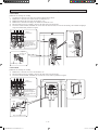
ELECTRICAL WIRING CONNECTION
09/12 class
[Method of mounting conduit]
A protection plate is fixed for protection from the high-voltage section.
Dismount the stop valve cover by removing the screw.
Dismount the protection plate by removing the 2 screws.
Dismount the conduit mounting cover by removing the 2 screws.
Pass wires through the conduit and secure them with a lock nut.
After completing the work, reattach the stop valve cover, the conduit mounting cover, and the protection plate to its
original position.
•
1)
2)
3)
4)
5)
18/24 class
[Method of mounting conduit]
Dismount the service lid by removing the screws.
Pass wires through the conduit and secure them with a lock nut.
After completing the work, reattach the service lid to its original position.
1)
2)
3)
Power supply
terminal block
Shape wires so that
the proctection plate
and conduit mounting
plate fit securely.
Conduit
mounting
plate
Conduit
Lock nut
Protection plate
Screws
Conduit
mounting
cover
Screws
Service lid
Screws
Screws
Power supply
terminal block
Conduit mounting plate
Conduit
Lock nut
Shape wires so that
the proctection plate
and conduit mounting
plate fit securely.
1 IM-5WMYJ(R)-0617(0)-DAIKIN USA14 141 IM-5WMYJ(R)-0617(0)-DAIKIN USA14 14 10/12/17 10:31:02 AM10/12/17 10:31:02 AM

English
1-15
SPECIAL PRECAUTIONS WHEN DEALING WITH R410A UNIT
R410A is a new HFC refrigerant which does not damage the
ozone layer. The working pressure of this new refrigerant is
1.6 times higher than conventional refrigerant (R22), thus
proper installation/servicing is essential.
Never use refrigerant other than R410A in an air conditioner
which is designed to operate with R410A.
POE or PVE oil is used as lubricant for R410A compressor,
which is different from the mineral oil used for R22
compressor. During installation or servicing, extra precaution
must be taken not to expose the R410A system too long
to moist air. Residual POE or PVE oil in the piping and
components can absorb moisture from the air.
To prevent mischarging, the diameter of the service port
on the flare valve is different from that of R22.
•
•
•
Use tools and materials exclusively for refrigerant R410A.
Tools exclusively for R410A are manifold valve, charging
hose, pressure gauge, gas leak detector, flare tools, torque
wrench, vacuum pump and refrigerant cylinder.
As an R410A air conditioner incurs higher pressure
than R22 units, it is essential to choose the copper pipes
correctly.
If the refrigerant gas leakage occurs during installation/
servicing, be sure to ventilate fully. If the refrigerant gas
comes into contact with fire, a poisonous gas may occur.
When installing or removing an air conditioner, do not
allow air or moisture to remain in the refrigerant cycle.
•
•
•
•
VACUUMING AND CHARGING
Vacuuming is necessary to eliminate all moisture and air from the system.
Vacuuming The Piping And The Indoor Unit
Except for the outdoor unit which is pre-charged with
refrigerant, the indoor unit and the refrigerant connection
pipes must be air-purged because the air containing moisture
that remains in the refrigerant cycle may cause malfunction
of the compressor.
Remove the caps from the valve and the service port.
Connect the center of the charging gauge to the vacuum
pump.
Connect the charging gauge to the service port of the 3-way
valve.
Start the vacuum pump. Evacuate for approximately 30
minutes. The evacuation time varies with different vacuum
pump capacity. Confirm that the charging gauge needle has
moved towards -14.7psi (-760mmHg).
Caution
If the gauge needle does not move to -14.7psi (-760mmHg),
be sure to check for leakage at flare type connection of
the indoor and outdoor unit and repair the leak before
proceeding to the next step.
Close the valve of the changing gauge and stop the vacuum
pump.
On the outdoor unit, open the suction valve (3 way) and
liquid valve (2 way) (in anti-clockwise direction) with
5/32" (4mm) key for hexagon sacked screw.
Charge Operation
This operation must be done by using a gas cylinder and a
precise weighing machine. The additional charge is topped-up
into the outdoor unit using the suction valve via the service
port.
Remove the service port cap.
Connect the low pressure side of the charging gauge to the
suction service port center of the cylinder tank and close
the high pressure side of the gauge. Purge the air from the
service hose.
Start the air conditioner unit.
Open the gas cylinder and low pressure charging valve.
When the required refrigerant quantity is pumped into
the unit, close the low pressure side and the gas cylinder
valve.
Disconnect the service hose from service port. Put back
the service port cap.
•
•
•
•
•
•
•
•
•
•
•
•
•
Refrigerant Piping
Outdoor Unit 3 ways valve
Allen key
Service Port
Flare nut
HIGH PRESSURE GAUGE
GAUGE MANIFOLD
LOW PRESSURE GAUGE
HANDLE HI (ALWAYS CLOSED)
CHARGE HOSE
-14.7psi (-760mmHg)
HANDLE LO
CHARGE HOSE
VACUUM PUMP
ADAPTER FOR
COUNTER FLOW
PREVENTION
CHECK VALVE
LIQUID VALVE
HIGH PRESSURE GAUGE
LOW PRESSURE GAUGE
GAUGE MANIFOLD
-14.7psi (-760mmHg)
HANDLE LO
HANDLE HI (ALWAYS CLOSED)
CHARGE HOSE
CHARGE HOSE
CHECK VALVE
LIQUID VALVE
GAS VALVE
(3-WAY)
CONFIGURATION OF AIR
PURGE BY CHARGING
GAS VALVE
(3-WAY)
CONFIGURATION OF AIR
PURGE BY CHARGING
1 IM-5WMYJ(R)-0617(0)-DAIKIN USA15 151 IM-5WMYJ(R)-0617(0)-DAIKIN USA15 15 10/12/17 10:31:02 AM10/12/17 10:31:02 AM

1-16
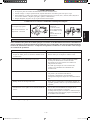
COOL/HEAT/TIMER
(BLUE/RED/VIOLET)
Operation
BLUE
Cool mode
RED
Heat mode
RED
Auto mode in Heating operation
BLUE
Auto mode in Cooling operation
VIOLET
Timer on
BLUE
Fan mode on
BLUE
Dry mode on
RED
Defrost operation
BLUE
Unit error
ON
Blinking
IR Signal Receiver
When an infrared remote control operating signal has been
transmitted, the signal receiver on the indoor unit will respond
as below to confirm acceptance of the signal transmission.
LED Indicator Lights for Cooling Unit/Heat Pump
Unit
Cooling Unit/Heat Pump Unit
The table shows the LED indicator lights for the air conditioner
unit under normal operation and fault conditions. The LED
indicator lights are located at the side of the air conditioner
unit.
The heat pump units are equipped with an “auto” mode
sensor whereby it will provide reasonable room temperature
by switching automatically to either “cool” or “heat” mode
according to the temperature set by the user.
Cool/Heat/Timer
IR Receiver
ON/OFF switch
IR Receiver
INDICATOR LIGHTS
ON to OFF 1 Long Beep
OFF to ON
Pump down / Cool force on
2 Short Beep
Others 1 Short Beep
LED Indicator Lights: Normal Operation And Fault Conditions For Cooling/Heat Pump Unit
Additional refrigerant charge [oz (g)] per additional 3.28ft (1m) length as tabulated.
The refrigerant is pre-charged in the outdoor unit. If the piping length is less than 25ft (7.6m), then additional charge after
vacuuming is not necessary. If the piping length is more than 25ft (7.6m), then use the additional charge value as indicated
in the table.
Example:
FTXB09 & RXB09 with 39.4ft (12m) piping length, additional piping length is 14.4ft (4.4m).
Thus, Additional charge = 14.4ft (4.4m)x 0.21oz/ft [20g/m]
= 3.024oz [88.0g]
Model
Indoor (FTXB/FTKB) 09 12 18 24
Outdoor (RXB/RKB) 09 12 18 24
Additional charge [oz/ft (g/m)]
0.21 (20) 0.21 (20) 0.21 (20) 0.21 (20)
ADDITIONAL CHARGE
ON/OFF
1 IM-5WMYJ(R)-0617(0)-DAIKIN USA16 161 IM-5WMYJ(R)-0617(0)-DAIKIN USA16 16 10/12/17 10:31:02 AM10/12/17 10:31:02 AM

English
1-17
FRONT
Recess on
main unit
AIR FILTER
Open the front panel.
Hold the panel at the recesses on the main unit
(2 recesses on right and left sides) and lift it until it
stops.
1.
•
Pull out the air filters.
Push a little upwards the tab at the center of each air
filter, then pull it down.
2.
•
Clean or replace each filter.
When shaking off remaining water, do not wring the
filter.
3.
•
Set the air filter and close the front panel.
Insert claws of the filters into slots of the front panel.
Close the front panel slowly and push the panel at the
3 points. (1 on each side and 1 in the middle.)
The air filter have a symmetrical form in the horizontal
direction.
4.
•
•
68/20
64.4/18
50/10
32/0
14/-10
5/-15
-4/-20
50/10 59/15 68/20 77/25 86/30
80.6/27
122/50
114.8/46
109.4/43
104/40
86/30
68/20
50/10
32/0
50/10 59/15
57.2/14 66.2/19 73.4/23
68/20 77/25
INDOOR TEMP (°F/°CWB)
COOLING HEATING
OUTDOOR TEMP (°F/°CWB)
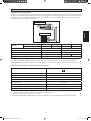
Heat Pump Model
INDOOR TEMP (°F/°CDB)
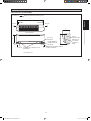
OPERATING RANGE
Model: FTXB 09/12 RXB 09/12
68/20
64.4/18
50/10
32/0
14/-10
5/-15
-4/-20
50/10 59/15 68/20 77/25 86/30
80.6/27
122/50
114.8/46
109.4/43
86/30
104/40
68/20
50/10
32/0
14/-10
-4/-20
50/10 59/15 68/20 77/25
73.4/2366.2/1957.2/14
INDOOR TEMP (°F/°CWB)
COOLING HEATING
OUTDOOR TEMP (°F/°CWB)
INDOOR TEMP (°F/°CDB)
DB: Dry bulb WB: Wet bulb
Model: FTXB 18/24 RXB 18/24
OUTDOOR TEMP (°F/°CDB)
OUTDOOR TEMP (°F/°CDB)
DB: Dry bulb WB: Wet bulb
Cooling Only Model
Model: FTKB 09/12 RKB 09/12 Model: FTKB 18/24 RKB 18/24
122/50
114.8/46
109.4/43
104/40
86/30
68/20
50/10
32/0
50/10 59/15
57.2/14 66.2/19 73.4/23
68/20 77/25
INDOOR TEMP (°F/°CWB)
COOLING
OUTDOOR TEMP (°F/°CDB)
DB: Dry bulb WB: Wet bulb
122/50
114.8/46
109.4/43
86/30
104/40
68/20
50/10
32/0
14/-10
-4/-20
50/10 59/15 68/20 77/25
73.4/2366.2/1957.2/14
INDOOR TEMP (°F/°CWB)
COOLING
OUTDOOR TEMP (°F/°CDB)
1 IM-5WMYJ(R)-0617(0)-DAIKIN USA17 171 IM-5WMYJ(R)-0617(0)-DAIKIN USA17 17 10/12/17 10:31:03 AM10/12/17 10:31:03 AM

1-18
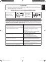
SERVICE AND MAINTENANCE
Open the front panel.
Hold the panel at the recesses on the main unit
(2 recesses on right and left sides) and lift it until it
stops.
1.
•
Remove the front panel.
While lifting the front panel further, slide it to the right
and pull it to the front side. The left rotating shaft is
detached. Slide the right rotating shaft to the left and
pull it to the front side to remove it.
2.
•
Attach the front panel.
Align the right and left rotating shafts of the front panel
with the grooves and push them all the way in.
Gently close the front panel. (Push both ends and the
center on the front panel.)
3.
•
•
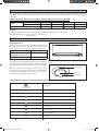
Service Parts Maintenance Procedures Period
Indoor air filter Remove any dust adhering to the filter by using a vacuum cleaner or wash in lukewarm
water (below 40°C/104°F) with a neutral cleaning detergent.
Rinse the filter well and dry before placing it back onto the unit.
Do not use gasoline, volatile substances or chemicals to clean the filter.
1.
2.
3.
At least once
every 2 weeks.
More frequently
if necessary.
Indoor unit Clean any dirt or dust on the grille or panel by wiping it with a soft cloth soaked in
lukewarm water (below 40°C/104°F) and a neutral detergent solution.
Do not use gasoline, volatile substances or chemicals to clean the indoor unit.
1.
2.
At least once
every 2 weeks.
More frequently
if necessary.
! CAUTION
• Avoid direct contact of any coil treatment cleaners on plastic part. This may cause plastic part to deform as a result
of chemical reaction.
Step 1
Front Panel Opening & Closing Sequence
To open the front panel
1) Lift up the two tips of front panel 1 until it stops at the pre-fix position.
2) Lift up the two tips of front panel 2 to open it and access to inner parts.
To close the front panel, reverse the steps of opening sequence. Slot in the ribs (4 ribs at each side, total 8 ribs), carefully at
both left and right. Then, press the panel forward till it closes tight. Refer to 3
Rotating shaft
Recess on
main unit
Step 2
Step 3 Step 3
1 IM-5WMYJ(R)-0617(0)-DAIKIN USA18 181 IM-5WMYJ(R)-0617(0)-DAIKIN USA18 18 10/12/17 10:31:03 AM10/12/17 10:31:03 AM
La page charge ...
La page charge ...
La page charge ...
La page charge ...
La page charge ...
La page charge ...
La page charge ...
La page charge ...
La page charge ...
La page charge ...
La page charge ...
La page charge ...
La page charge ...
La page charge ...
La page charge ...
La page charge ...
La page charge ...
La page charge ...
La page charge ...
La page charge ...
La page charge ...
La page charge ...
La page charge ...
La page charge ...
La page charge ...
La page charge ...
La page charge ...
La page charge ...
La page charge ...
La page charge ...
La page charge ...
La page charge ...
La page charge ...
La page charge ...
La page charge ...
La page charge ...
La page charge ...
La page charge ...
La page charge ...
La page charge ...
La page charge ...
La page charge ...
La page charge ...
La page charge ...
-
 1
1
-
 2
2
-
 3
3
-
 4
4
-
 5
5
-
 6
6
-
 7
7
-
 8
8
-
 9
9
-
 10
10
-
 11
11
-
 12
12
-
 13
13
-
 14
14
-
 15
15
-
 16
16
-
 17
17
-
 18
18
-
 19
19
-
 20
20
-
 21
21
-
 22
22
-
 23
23
-
 24
24
-
 25
25
-
 26
26
-
 27
27
-
 28
28
-
 29
29
-
 30
30
-
 31
31
-
 32
32
-
 33
33
-
 34
34
-
 35
35
-
 36
36
-
 37
37
-
 38
38
-
 39
39
-
 40
40
-
 41
41
-
 42
42
-
 43
43
-
 44
44
-
 45
45
-
 46
46
-
 47
47
-
 48
48
-
 49
49
-
 50
50
-
 51
51
-
 52
52
-
 53
53
-
 54
54
-
 55
55
-
 56
56
-
 57
57
-
 58
58
-
 59
59
-
 60
60
-
 61
61
-
 62
62
-
 63
63
-
 64
64


Daikin FTXB12AXVJU Guide d'installation
- Catégorie
- Climatiseurs split-system
- Taper
- Guide d'installation
- Ce manuel convient également à
dans d''autres langues
- English: Daikin FTXB12AXVJU Installation guide
- español: Daikin FTXB12AXVJU Guía de instalación
Documents connexes
Autres documents
-
McQuay M5WMY10KR Guide d'installation
-
-
Acson 5CEY28ER Guide d'installation
-
Acson 5MSY18BR Guide d'installation
-
mundoclima Series MUPR-H8A Guide d'installation
-
 Siesta AHQ100CV1 Guide d'installation
-
Mitsubishi PUHY-HP-THMU-A Mode d'emploi
-
Fujitsu UOMH18AFXZJ Guide d'installation
-
Mitsubishi Electric PURY-HP144 Guide d'installation
-
Haier HSU12VHJDBW Guide d'installation
