Thermador PRD366GHU Guide d'installation

Catégorie
Cuisinières
Taper
Guide d'installation

Ce manuel convient également à

THERMADOR PROFESSIONAL
TM
PRO HARMONY
®
Dual Fuel Ranges
THERMADOR PROFESSIONAL
TM
PRO HARMONY
®
Dual Fuel Ranges
Cuisinières Mixtes PROFESSIONAL PRO HARMONY
mc
de THERMADOR
Estufas Mixtas PROFESSIONAL PRO HARMONY
®
de THERMADOR
Table of Contents............................................................................... 2
Table de Matières ............................................................................ 28
Índice de Materias ........................................................................... 54
Models | Modèles | Modelos
PRD304GHC
PRD304GHU
PRD364GDHC
PRD364GDHU
PRD366GHC
PRD366GHU
PRD486GDHC
PRD486GDHU
PRD364NLHU
PRD364NLHC
PRD486NLHU
PRD486NLHC
PRD484NCHU
PRD484NCHC
Table of Contents English 2
Table of Contents
This THERMADOR
®
appliance is made by
BSH Home Appliances Corporation
1901 Main Street, Suite 600
Irvine, CA 92614
Questions?
1-800-735-4328
www.thermador.com
We look forward to hearing from you!
Safety Instructions ....................................................................................................................................................... 3
Installation ..................................................................................................................................................................... 5
Planning Information ................................................................................................................................................. 5
STEP 1: Ventilation Requirements .......................................................................................................................... 5
STEP 2: Cabinet Preparation ................................................................................................................................... 6
STEP 3: Unpacking, Moving and Placing the Range ............................................................................................. 12
STEP 4: Installing Anti-Tip Device ......................................................................................................................... 13
STEP 5: Gas Requirements and Hookup .............................................................................................................. 14
STEP 6: Electrical Requirements, Connection & Grounding ................................................................................. 16
STEP 7: Backguard Installation (optional) .............................................................................................................. 18
STEP 8: Door Removal and Reinstallation ............................................................................................................ 22
STEP 9: Placing and Leveling the Range............................................................................................................... 24
STEP 10: Burner Test ............................................................................................................................................ 26
Installer Checklist ....................................................................................................................................................... 27
Customer Support, Accessories & Parts .....................................................................................................back page
Safety Definitions
NOTICE: This indicates that damage to the appliance or property may occur as a result of non-compliance with this
advisory.
Note: This alerts you to important information and/or tips.
WARNING
This indicates that death or serious injuries may occur as
a result of non-observance of this warning.
CAUTION
This indicates that minor or moderate injuries may occur
as a result of non-observance of this warning.
Installation Instructions English 3
Safety
IMPORTANT SAFETY INSTRUCTIONS
READ AND SAVE THESE INSTRUCTIONS
Before You Begin
IMPORTANT: Save these Instructions for the Local Gas
Inspectors use.
INSTALLER: Please leave these Installation Instructions
with this unit for the owner.
OWNER: Please retain these instructions for future
reference.
Examine the appliance after unpacking it. In the event of
transport damage, do not plug it in.
Remove all tape and packaging before using the appliance.
Destroy the packaging after install. Never allow children to
play with packaging material.
IMPORTANT:
Local codes vary. Installer is responsible for ensuring that
the installation, gas connections, and grounding comply
with all applicable codes. Failure to follow appropriate local
codes and regulations may void the warranty.
NOTE: This range is NOT designed for installation in
manufactured (mobile) homes or Recreational Park
Trailers.
GROUNDING INSTRUCTIONS
This appliance must be grounded. Grounding reduces the
risk of electric shock by providing a safe pathway for
electric current in the event of a short circuit.
DO NOT install this range outdoors.
WARNING
ELECTRICAL SHOCK HAZARD
Disconnect power before installing or servicing.
Before turning power ON, be sure that all
controls are in the OFF position. Failure to do
so can result in death or electrical shock.
FOR MASSACHUSETTS INSTALLATIONS:
1. Installation must be performed by a qualified or
licensed contractor, plumber or gas fitter qualified or
licensed by the state, province or region where this
appliance is being installed.
2. Shut-off valve must be a “T” handle gas cock.
3. Flexible gas connector must not be longer than 36''
(914 mm).
WARNING
A child or adult can tip the range over and
be killed or seriously injured. Verify that
the anti-tip bracket is securely installed.
Ensure the anti-tip bracket is engaged
when the range is moved.
DO NOT operate the range without the anti-tip bracket in
place. Failure to follow the instructions in this manual
can result in death or serious burns to children and
adults.
Check for proper installation and use of anti-tip bracket.
Carefully tip range forward pulling from the back to
ensure that the anti-tip bracket engages the range leg
and prevents tip-over. Range should not move more
than 1'' (2.5 cm).
WARNING
If the information in this manual is not followed exactly, a
fire or explosion may result causing property damage,
personal injury or death.
DO NOT store or use gasoline or other flammable
vapors and liquids in the vicinity of this or any other
appliance.
WHAT TO DO IF YOU SMELL GAS
DO NOT try to light any appliance.
DO NOT touch any electrical switch.
DO NOT use any phone in your building.
Immediately call your gas supplier from a
neighbors phone. Follow the gas suppliers
instructions.
If you cannot reach your gas supplier, call the
fire department.
Installation and service must be performed by a
qualified installer, service agency or the gas
supplier.
Installation Instructions English 4
IMPORTANT SAFETY INSTRUCTIONS
READ AND SAVE THESE INSTRUCTIONS
Gas Type Verification
Verify the type of gas supplied to the location. Ensure that
the appliance is connected to the type of gas for which it is
certified. All models are certified for use with natural gas.
Field conversion of the appliance for use with propane gas
supply will require a conversion kit (PALPKITHN).
Gas Supply
Natural Gas — 6 inch water column. (14.9 mb) min., 14
inch (34.9 mb) maximum
Propane Gas — 11 inch water column. (27.4 mb) min., 14
inch (34.9 mb) maximum
Electric Power Supply
See “STEP 6: Electrical Requirements, Connection &
Grounding” on page 16 for specifications.
Check local building codes for the proper method of
appliance installation. Local codes vary and
it is the
responsibility of the installer to ensure installation is in
accordance with these codes. Installation, electrical
connections and grounding must comply with all applicable
codes. In the absence of local codes the appliance should
be installed in accordance with the National Fuel Gas Code
ANSI Z223.1/NFPA 54 current issue and National Electrical
Code ANSI/NFPA 70-current issue. In Canada, installation
must be in accordance with the CAN 1-B149.1 and .2 –
Installation Codes for Gas Burning Appliances and/or local
codes.
This appliance complies with the following standards:
UL 858, Standard for the Safety of Household Electric
Ranges
ANSI Z21.1, American National Standard for
Household Cooking Gas Appliances
CAN 1-1. 1-M81, Domestic Gas Ranges
CAN/CSA-C22.2 No. 61, Household Cooking Ranges
It is the responsibility of the owner and the installer to
determine if additional requirements and/or standards
apply to specific installations.
IMPORTANT:
When installing against a combustible surface, a Low
Backguard is required. A THERMADOR
TM
Low Backguard
must be purchased separately. See Step 7 for backguard,
kits and installation information.
When using the Flush Island Trim, THERMADOR
recommends a minimum 12'' (305 mm) rear clearance to a
combustible surface (see “Installation Clearances”).
Clearances from non-combustible materials are not part of
the ANSI Z21.1 scope and are not certified by
CSA. Clearances of less than 12'' (305 mm) must be
approved by the local codes and/or by the local authority
having jurisdiction.
Refer to Table 3, Backguard Kit Model Numbers, for the
correct backguard models that are designed for this range.
After selecting the correct backguard, the range must be
installed properly, using the minimum clearances to
combustible surfaces specified in the Cabinet Preparation
instructions beginning on page 6.
CAUTION
When connecting the unit to propane gas, make certain
the propane gas tank is equipped with its own high-
pressure regulator in addition to the pressure regulator
supplied with the range. The maximum gas pressure to
this appliance must not exceed 14.0” water column
(34.9 mb) from the propane gas tank to the pressure
regulator.
WARNING
To avoid possible burn or fire hazard, a backguard
designed specifically for this range must be installed
whenever the range is used.
CAUTION
To eliminate risk of burns or fire caused by reaching over
heated surface units, cabinet storage located above the
surface units should be avoided.
CAUTION
This unit is designed as a cooking appliance. Based on
safety considerations, never use it for warming or
heating a room.
WARNING
State of California Proposition 65 Warnings:
This product contains chemicals known to the State of
California to cause cancer, birth defects or other
reproductive harm.
Installation Instructions English 5
Installation
Planning Information
Before using your appliance, be sure to read this manual.
Pay special attention to the Important Safety Instructions
located at the beginning of the manual.
STEP 1: Ventilation
Requirements
Refer to the Ventilation Planning Guide for approved
ventilation combinations.
It is strongly recommended that this appliance be installed
in conjunction with a THERMADOR vent hood. Due to the
high heat capability of this unit, particular attention should
be paid to the hood and duct work installation to assure it
meets local building codes.
Downdraft ventilation should not be used. The Ventilation
Planning Guide indicates the ventilation hood options and
blower capacity guidelines that are recommended for use
with all THERMADOR ranges.
Due to the high heat of the rangetop burners, do not install
a microwave oven/ventilator combination above the range,
as these type of units do not provide the proper ventilation
and are not suitable for use with the range.
IMPORTANT:
Ventilation hoods and blowers are designed for use with
single wall ducting. However, some local building codes or
inspectors may require double wall ducting. Consult local
building codes and/or local agencies, before starting, to
assure that hood and duct installation will meet local
requirements.
NOTICE: Most range hoods contain combustible
components which must be considered when planning the
installation.
Ventilation Preparation
1. Select Hood and Blower Models:
For wall installations, the hood width must, at a
minimum, equal the width of the range. Where
space permits, a hood larger in width than the
range/rangetop may be desirable for improved
ventilation performance.
For island installations, the hood width should
overhang the width of the range by a minimum of
3" (76 mm) on each side.
2. Hood Placement:
For best smoke elimination, the lower edge of the
hood should be installed 30" (762 mm) above the
range cooking surface (see “Installation
Clearances”).
If the hood contains any combustible materials (i.e.
a wood covering), it must be installed a minimum of
36" (914 mm) above the cooking surface (see
“Installation Clearances”).
TOOLS NEEDED
7/16'' box end wrench or
ratchet
1/8'' (3.17 mm) drill bit
3/16'' (4.76 mm) drill bit 12'' Adjustable wrench
Hand or electric drill Tape measure
T-20 Torx screwdriver Marking instrument
Level Furniture dolly
Phillips & flathead
screwdrivers
Protective gloves
ITEMS NOT INCLUDED
Drywall / Concrete Anchors Pipe Compound / Tape
Rope/Twine ¾" (19 mm) Flex Line
Strain Relief Cord Kit or Conduit
2 – NPT Flare Adapters
WARNING
This appliance should not be installed with a ventilation
system that directs air in a downward direction toward
the range. This type of ventilation system may cause
ignition and combustion problems with the appliance
resulting in personal injury, property damage, or
unintended operation. Ventilating systems that direct the
air upwards do not have any restriction.
Installation Instructions English 6
3. Consider Make-Up Air:
Due to the high volume of ventilation air, a source
of outside replacement air is recommended. This is
particularly important for tightly sealed and
insulated homes. A qualified heating and
ventilating contractor should be consulted.
STEP 2: Cabinet Preparation
The range is a free standing unit. If the unit is to be
placed adjacent to cabinets, the clearances shown in
“Installation Clearances” beginning on page 7 are
required. The same clearances apply to island
installations, except for the overhead cabinets, which
must have a space wide enough to accept the flared
island hood.
Any openings in the wall behind the range and in the
floor under the range must be sealed.
The gas and electrical supply should be within the
zones shown in Figure 5 on page 11.
When installing against a combustible surface, a Low
Backguard is required. A THERMADOR
TM
Low
Backguard must be purchased separately (see Table 3
on page 18).
When using the Flush Island Trim, THERMADOR
recommends a minimum 12'' (305 mm) rear clearance
to a combustible surface (see “Installation
Clearances”). Clearances from non-combustible
materials are not part of the ANSI Z21.1 scope and are
not certified by CSA. Clearances of less than 12''
(305 mm) must be approved by the local codes and/or
by the local authority having jurisdiction.
When the range is installed against a combustible side
wall a minimum clearance of 5'' (127 mm) is needed
from the side of the range to the wall.
Always keep appliance area clear from combustible
materials, gasoline and other flammable vapors and
liquids.
The maximum depth of overhead cabinets installed on
either side of the hood is 13" (330 mm). Wall cabinets
must be 18'' (457 mm) above the countertop.
The top edges of the range’s side panels must be on
the same or higher level as the adjacent countertop. If
the range is operated while at a lower height relative to
the adjacent cabinet, the cabinet could be exposed to
excessive temperatures, causing damage to the
cabinet and countertop.
DO NOT obstruct the flow of combustion and
ventilation air to the unit.
There is a 36'' (914 mm) minimum clearance required
between the top of the cooking surface and the bottom
of an unprotected cabinet. A 30'' (762 mm) clearance
can be used when the bottom of the wood or metal
cabinet is protected by not less than 1/4'' (6 mm) of a
flame retardant material covered with not less than No.
28 MSG sheet steel, 0.015'' (0.38 mm) thick stainless
steel, 0.024'' (0.61 mm) aluminum, or 0.02'' (0.51 mm)
thick copper.
Flame retardant materials bear the mark:
UNDERWRITERS LABORATORIES INC. CLASSIFIED
MINERAL AND FIBER BOARDS SURFACE BURNING
CHARACTERISTICS, followed by the flame spread and
smoke ratings. These designations are shown as “FHC
(FIame Spread/Smoke Developed).” Materials with “O”
flame spread ratings are flame retardant. Local codes may
allow other flame spread ratings. It is the responsibility of
the installer to ensure installation is in accordance with
these ratings.
Installation Instructions English 7
Installation Clearances
Installation Clearances with Lowback
Figure 1: Cabinet Clearances
5
" (127 mm) min.
to combustible
sidewalls
5
" (127 mm) mi
n.
to combustib
le
sidew
alls
5
" (127 mm) min.
to combustible
sidewalls
30" (762 mm) min.
from bottom of overhead
hood to cooking surface.
36" (914 mm) min. if
hood contains
combustible material
30" (762 mm) mi
n.
from bottom of overhead
hood to cooking s
urface.
36" (914 mm) mi
n. if
hood contains
combustible material
30" (762 mm) min.
from bottom of overhead
hood to cooking surface.
36" (914 mm) min. if
hood contains
combustible material
13" max.
cabinet
depth
13" max.
cabinet
depth
13" max.
cabinet
depth
m CAUTION!
36" (914 mm) min.
to combustible
material
from Cooking
Surface
CAUTION!
36" (914 mm) min.
to combustible
material
from Cooking
Surface
CAUTION!
36" (914 mm) min.
to combustible
material
from Cooking
Surface
as defined in the “National Fuel Gas Code” (ANSI Z223.1, Current Edition).
Clearances from non-combustible materials are not part of the ANSI Z21.1
scope and are not certified by CSA. Clearances of less than 12" (305 mm)
must be approved by the local codes and/or by the local authority having
jurisdiction.
The range height is adjustable.
The level of the range top must
be at the same level or above
the counter top level.
*35 ¾" (908 mm) Min. range
height with leveling legs fully
retracted.
*37 ¼" (946 mm) Max. range
height with leveling legs fully
extended.
The range height is adjustable.
The level of the range top must
be at the same level or above
the counter top level.
*35 ¾" (908 mm) Min. range
height with leveling legs fully
retracted.
*37 ¼" (946 mm) Max. range
height with leveling legs fully
extended.
The range height is adjustable.
The level of the range top must
be at the same level or above
the counter top level.
*35 ¾" (908 mm) Min. range
height with leveling legs fully
retracted.
*37 ¼" (946 mm) Max. range
height with leveling legs fully
extended.
30", 36", or 48"
(762, 914, or 1219 mm)
30", 36", or 48"
(762, 914, or 1219 mm)
30", 36", or 48"
(762, 914, or 1219 mm)
For Gas Supply &
Electrical Zones
see Figure 5.
For Gas Supply &
Electrical Zones
see Figure 5.
For Gas Supply &
Electrical Zones
see Figure 5.
18
" (457 mm)
minimum
18
" (457 mm)
mini
mum
18
" (457 mm)
minimum
See the Ventilation Planning Guide
for recommended hood options.
See the Ventilation Planning Guide
for recommended hood options.
See the Ventilation Planning Guide
for recommended hood options.
Installation Instructions English 8
Figure 2: Installation Clearances with a Low Backguard
as defined in the “National Fuel Gas Code” (ANSI Z223.1, Current Edition).
Clearances from non-combustible materials are not part of the ANSI Z21.1
scope and are not certified by CSA. Clearances of less than 12” (305 mm)
must be approved by the local codes and/or by the local authority having jurisdiction.
Combustible
Materials
28" (711 mm)
27¼" (692 mm)
36" (914 mm) min.
to combustible
materials
24" (610 mm)
max. recess depth
Combustible
Back Wall
35 ¾" (908 mm) Min.
37 ¼" (946 mm) Max.
23" (584 mm)
44⅞
"
(1140 mm)
Total Clearance
Installation Clearances with Low Backguard
9" (229 mm)
9" (229 mm)
9" (229 mm)
Low Back
24⅝" (625 mm)
24¾" (629 mm)
Installation Instructions English 9
Installation Clearances with Flush Island Trim
Figure 3: Cabinet Clearances with Flush Island Trim
5
" (127 mm) min.
to combustible
sidewalls
5
" (127 mm) mi
n.
to combusti
ble
sidew
alls
5
" (127 mm) min.
to combustible
sidewalls
30" (762 mm) min.
from bottom of overhead
hood to cooking surface.
36" (914 mm) min. if
hood contains
combustible material
30" (762 mm) mi
n.
from bottom of overhead
hood to cooking s
urface.
36" (914 mm) mi
n. if
hood contains
combustible material
30" (762 mm) min.
from bottom of overhead
hood to cooking surface.
36" (914 mm) min. if
hood contains
combustible material
13" max.
cabinet
depth
13" max.
cabinet
depth
13" max.
cabinet
depth
m CAUTION!
36" (914 mm) mi
to combustible
material
from Cooking
Surface
CAUTION!
36" (914 mm) min.
to combustible
material
from Cooking
Surface
CAUTION!
36" (914 mm) mi
to combustible
material
from Cooking
Surface
as defined in the “National Fuel Gas Code” (ANSI Z223.1, Current Edition).
Clearances from non-combustible materials are not part of the ANSI Z21.1
scope and are not certified by CSA. Clearances of less than 12" (305 mm)
must be approved by the local codes and/or by the local authority having
jurisdiction.
The range height is adjustable.
The level of the range top must
be at the same level or above
the counter top level.
*35 ¾" (908 mm) Min. range
height with leveling legs fully
retracted.
*37 ¼" (946 mm) Max. range
height with leveling legs fully
extended.
The range height is adjustable.
The level of the range top must
be at the same level or above
the counter top level.
*35 ¾" (908 mm) Min. range
height with leveling legs fully
retracted.
*37 ¼" (946 mm) Max. range
height with leveling legs fully
extended.
The range height is adjustable.
The level of the range top must
be at the same level or above
the counter top level.
*35 ¾" (908 mm) Min. range
height with leveling legs fully
retracted.
*37 ¼" (946 mm) Max. range
height with leveling legs fully
extended.
30", 36", or 48"
(762, 914, or 1219 mm)
30", 36", or 48"
(762, 914, or 1219 mm)
30", 36", or 48"
(762, 914, or 1219 mm)
For Gas Supply &
Electrical Zones
see Figure 5.
For Gas Supply &
Electrical Zones
see Figure 5.
For Gas Supply &
Electrical Zones
see Figure 5.
18
" (457 mm)
minimum
18
" (457 mm)
mini
mum
18
" (457 mm)
minimum
See the Ventilation Planning Guide
for recommended hood options.
See the Ventilation Planning Guide
for recommended hood options.
See the Ventilation Planning Guide
for recommended hood options.
Shaded area above
countertop indicates min.
clearance to combustible
surfaces, combustible
materials cannot be located
within this area.
Shaded area above
countertop indicates min.
clearance to combustible
surfaces, combustible
materials cannot be located
within this area.
Shaded area above
countertop indicates min.
clearance to combustible
surfaces, combustible
materials cannot be located
within this area.
Installation Instructions English 10
Figure 4: Installation Clearances with a Flush Island Trim
as defined in the “National Fuel Gas Code” (ANSI Z223.1, Current Edition).
Clearances from non-combustible materials are not part of the ANSI Z21.1
scope and are not certified by CSA. Clearances of less than 12” (305 mm)
must be approved by the local codes and/or by the local authority having jurisdiction.
Combustible
Materials
28" (711 mm)
27¼" (692 mm)
36" (914 mm) min .
to combustible
materials
24" (610 mm)
max. recess depth
Cantilever
23" (584 mm)
44⅞
"
(1140 mm)
Total Clearance
Installation Clearances with Flush Island Trim
24⅝" (625 mm)
24¾" (629 mm)
If an inner wall
is used under
the cantilever counter
top, there should be a
⅛" (3 mm) gap from
the rear of the range
to the inner wall.
12" (305 mm) min. to
combustible surface
with Flush Island Trim
12" (305 mm) min. to
combustible surface
with Flush Island Trim
12" (305 mm) min. to
combustible surface
with Flush Island Trim
For Flush Island
For Flush Island
For Flush Island
Trim installations,
Trim installations,
Trim installations,
counter surface should
have a cantilever edge
meeting the back
meeting the back
meeting the back
section of the Flush
Island Trim accessory.
Shaded area behind
range indicates
minimum clearance
to combustible surfaces,
combustible materials
cannot be located within
this area.
Shaded area behind
range indicates
minimum clearance
to combustible surfaces,
combustible materials
cannot be located within
this area.
Shaded area behind
range indicates
minimum clearance
to combustible surfaces,
combustible materials
cannot be located within
this area.
35 ¾" (908 mm) Min.
37 ¼" (946 mm) Max.
Installation Instructions English 11
Gas and Electric Supply Clearances
NOTICE:
If not already present, install gas shut-off valve in an
easily accessible location.
Make sure all users know where and how to shut off
the gas supply to the range.
Any opening in the wall behind the appliance and any
opening in the floor under the appliance must be
sealed.
The dual fuel ranges may be connected to the power
supply with a range supply cord kit or by hard-wiring to the
power supply. It is the responsibility of the installer to
provide the proper wiring components (cord or conduit and
wires) and complete the electrical connection as dictated
by local codes and ordinances, and/or the National Electric
Code. The units must be properly grounded. Refer to
“STEP 6: Electrical Requirements, Connection &
Grounding” on page 16 for details. Canadian models have
power cord supplied.
The range must be connected only to the type of gas
for which it is certified. If the range is to be connected to
propane gas, ensure that the propane gas supply tank is
equipped with its own high pressure regulator in addition to
the pressure regulator supplied with the range. (See “STEP
5: Gas Requirements and Hookup” beginning on page 14.)
NOTE: The range is designed for flush installation to the
back wall. For a successful installation, it may be
necessary to reposition the gas supply line and the
electrical cord as the range is pushed back to its final
position.
-- SUGGESTION: This may be accomplished by carefully
pulling on a rope or twine looped around the gas or
electrical supply line as the range is pushed back into
its final installed position.
Model A B C D
30'' (762 mm) 5¾'' (146 mm) 15
7
/
16
'' (392 mm) 5
13
/
16
'' (148 mm) 4Ǫ'' (111 mm)
36'' (913 mm) 8
1
/
16
'' (205 mm) 16
13
/
16
'' (503 mm) 8ǩ'' (206 mm) 4Ǫ'' (111 mm)
48'' (1219 mm) 4Ǫ'' (111 mm) 10¾'' (273 mm) 18
11
/
16
'' (475 mm) 5
15
/
16
'' (151 mm)
Figure 5: Gas and Electrical Supply Locations
10"
(254 mm)
10"
(254 mm)
10"
(254 mm)
B
B
C
C
3"
(76 mm)
3"
(76 mm)
3"
(76 mm)
A
A
D
D
2" (51 mm) max.
protrusion from wall
for gas or electrical
supply.
2" (51 mm) max.
protrusion from wall
for gas or electrical
supply.
2" (51 mm) max.
protrusion from wall
for gas or electrical
supply.
Gas Zone
30", 36" or 48" (762, 914 or 1219 mm)
For nearly-flush installation to
the back wall, the gas supply
line and electrical cord should
not go above this line.
For nearly-flush installation to
the back wall, the gas supply
line and electrical cord should
not go above this line.
For nearly-flush installation to
the back wall, the gas supply
line and electrical cord should
not go above this line.
Electric Zone
Electric Zone
Electric Zone
Installation Instructions English 12
Electrical Supply
Installation of the range must be planned so that rough-in
of terminal block for the receptacle or conduit connection
will allow maximum clearance to the rear of the unit.
When the power supply cord or conduit is connected to the
mating receptacle or terminal block cover, the combined
plug/receptacle or terminal block cover/conduit connector
should protrude no more than 2” (51 mm) from the rear
wall. See Figure 6.
Refer to Figure 10 on page 17 for location of terminal block
on unit. To minimize binding when the unit is connected to
the receptacle or terminal block, orient the receptacle or
conduit connector, and slide back into position.
When using a receptacle it may be necessary to recess the
receptacle's housing into the rear wall. Refer to Local
Electrical Code to determine the minimum volume for all
electrical / junction boxes.
Follow all local electrical codes.
Mount the receptacle securely to a wall stud, then seal
around the receptacle's housing.
NOTE: Canadian models have the power cord supplied
with range.
STEP 3: Unpacking and
Moving the Range
Unpacking the Range
1. Remove the outer carton and packing materials from
the shipping pallet but leave the adhesive-backed foam
layer over brushed-metal surfaces, to protect finish
from scratches, until the range is installed in its final
position.
2. It is recommended that the grates, griddle plate, burner
caps and oven racks be removed to facilitate handling.
If desired, the oven doors may also be removed (see
“STEP 8: Door Removal and Adjustment” on page 22).
Do not remove the griddle assembly.
Figure 6: Wall Connection
2” (51 mm) maximum
when plugged in
2” (51 mm)
maximum
Power Cord & Receptacle
Junction Box & Conduit
CAUTION
DO NOT lift the range by the oven doors
handle, as this may damage the door hinges
and cause the door to fit incorrectly.
DO NOT lift the appliance by the range’s
control panel.
The unit is heavy and should be handled
accordingly. Proper safety equipment such
as gloves and adequate manpower of at
least two people must be used in moving the
range to avoid injury and to avoid damage to
the unit or the floor.
Rings, watches, and any other loose items that may
damage the unit or otherwise might become entangled
with the unit should be removed.
Hidden surfaces may have sharp edges. Use caution
when reaching behind or under appliance.
DO NOT use a hand truck or appliance dolly on the back
or front of the unit. Handle from the side only.
30" 36" 48"
Shipping Weight 377 lbs
(171 kg)
395 lbs
(179 kg)
560 lbs
(254 kg)
Weight without
packing materials
293 lbs
(133 kg)
337 lbs
(153 kg)
470 lbs
(213 kg)
Table 1: Range Weight
Installation Instructions English 13
Moving the Range
Due to the weight, a furniture dolly with soft wheels or an
air lift should be used to move this unit. The weight must be
supported uniformly across the bottom.
NOTE: Step 4 through Step 8 must be completed before
the range is placed in its final position. For proper
performance, the range must be level. See “STEP 9:
Placing and Leveling the Range” on page 24 for leveling
instructions.
Removing the Pallet Bolts
1. To remove the (4) pallet bolts in the front and in the
back, use a 7/16'' wrench or ratchet and socket to
remove the pallet bolt from the bottom of the pallet.
Discard the wood packing block inserts.
2. Lift range and remove it from the pallet.
Use additional
help as required to remove from pallet.
3. Transport the range by dolly close to its final location.
Unit should not be dollied from the front.
4. The range can then be tipped back and supported on
the rear legs while the dolly is carefully removed. THE
FLOOR UNDER THE LEGS SHOULD BE
PROTECTED BEFORE PUSHING THE UNIT INTO
POSITION.
Step 4 through Step 8 must be completed before
the range is placed in its final position. For proper
performance, the range must be level. See
“STEP 9: Placing and Leveling the Range” on
page 24 for leveling instructions.
STEP 4: Installing the Anti-Tip
Device
For all ranges, an anti-tip device must be installed as per
these instructions.
ATTENTION – PROPERTY DAMAGE
Contact a qualified installer or contractor to determine
the proper method for drilling holes through the wall or
floor material (such as ceramic tile, hardwood, etc.)
Do not slide the range across an unprotected floor.
Failure to follow these instructions may result in
damage to wall or floor coverings.
Figure 7: Removal of Shipping Bolts
WARNING
RANGE TIPPING HAZARD:
All ranges can tip and injury can result.
To prevent accidental tipping of the
range, attach it to the floor by installing
the Anti-Tip Device supplied.
A risk of tip-over may exist if the
appliance is not installed in accordance
with these instructions. For all ranges an
anti-tip device
must be installed.
A child or adult can tip the range and be
killed.
DO NOT operate the range without the
anti-tip device in place and engaged.
Failure to do so can result in death or
serious burns to children or adults.
If the range is pulled away from the wall for cleaning,
service or for any other reason, ensure that the Anti-Tip
Device is properly re-engaged when the range is pushed
back against the wall. In the event of abnormal usage
(such as a person standing, sitting, or leaning on an
open door), failure to take this precaution can result in
tipping of the range. Personal injury might result from
spilled hot liquids or from the range itself.
WARNING
ELECTRICAL SHOCK HAZARD:
Use extreme caution when drilling holes into the wall
or floor as there may be concealed electrical wires.
Identify the electrical circuits that could be affected
by the installation of the Anti-Tip Device, then turn off
power to these circuits.
Failure to follow these instructions may result in
electrical shock or other personal injury.
Installation Instructions English 14
Important Installation Information
The anti-tip bracket may be attached to a solid wood
surface having a minimum wall thickness of ¾''
(19 mm).
The thickness of the wall or floor may require use of
longer screws, available at your local hardware store.
In all cases, at least two (2) of the bracket mounting
screws must be fastened to solid wood surface.
Use appropriate anchors when fastening the mounting
bracket to any material other than hard-wood or metal.
Hole location preparation
For walls, wall studs, or floors composed of solid wood
or metal, drill 1/8'' (3 mm) pilot holes.
For walls or floors composed of drywall, sheet-rock or
other soft materials, drill 3/16'' (5 mm) holes to a
minimum depth of 1¾'' (45 mm), then tap plastic
anchors into each of the holes using a hammer.
For walls or floors composed of concrete or concrete
block, drill 3/16'' (5 mm) holes to a minimum depth of
1¾'' (45 mm), then tap concrete anchors into each of
the holes using a hammer.
For walls or floors having ceramic tile covering, drill
3/16'' (5 mm) holes through the tile only, then drill into
the material behind the tile as indicated immediately
above.
Mounting Anti-Tip Bracket
The floor mounted bracket shall be installed as follows:
1. Place bracket on floor in position shown in Figure 8.
Bracket may be used in either corner of the
installation area.
2. Secure to floor and wall stud using the (4) 1½'' (38 mm)
Phillips head screws provided.
3. Later, when the unit is installed, the adjustable leg will
slide under the bracket, as shown in Figure 8.
4. If the range is moved to a new location, the Anti-Tip
Device must be removed and reinstalled.
STEP 5: Gas Requirements
and Hookup
Verify the type of gas being used at the installation site.
The appliance is shipped from the factory for use with
natural gas. It must be converted for use with propane.
A qualified technician or installer must do the
conversion. Make certain the range matches the type of
gas available at this location.
This appliance has been CSA certified for safe operation
up to an altitude of 2,000 ft (610 m) elevation above sea
level.
High Altitude — For altitudes above 2,000 feet (610 m)
elevation above sea level, adjustments can be made with
the High Altitude Packet included with the unit. If flame
performance is satisfactory, the contents in this packet will
not be required. It is required that a Certified Professional
make the high altitude adjustments during installation.
Propane (LP) Gas Appliances – The appliance must first
be converted for use with Propane (LP) Gas before it can
be converted for use at high altitude. A Propane (LP)
Conversion Kit (PALPKITHN) is required and available for
purchase from Thermador Customer Service.
SERVICE
PART NO.
QTY DESCRIPTION
00415078 4 Screw, Phillips, #10 x 1½''
00647936 1
Anti-Tip Bracket, Floor-
Mounted
Hardware provided is for mounting through standard
thickness wood studs. Installers are responsible to
provide hardware for other types of mounting situations.
Range Side Distance of X
30'' Left or Right 2¼'' (57 mm)
36'' Left or Right 2ǫ'' (67 mm)
48'' Left or Right 2½'' (64 mm)
Figure 8: Placement of Anti-Tip Bracket
C
L
C
L
x
x
x
x
Installation Instructions English 15
Hook Up
The gas supply connections shall be made by a competent
technician and in accordance with local codes or
ordinances. In the absence of local codes, the installation
must conform to the National Fuel Gas Code ANSI Z223.1/
NFPA54- current issue.
1. A manual gas shut-off valve must be installed external
to the appliance, in a location accessible from the front,
for the purpose of shutting off the gas supply. The
supply line must not interfere with the back of the unit.
Make sure the gas supply is turned off at the manual
shut-off valve before connecting the appliance.
The range is supplied with its own pressure
regulator that has been permanently mounted
within the range body.
2. Use a ¾'' (19 mm) flex line to connect between the gas
supply and the appliance gas inlet. The gas supply line
connection is located at the lower right portion of all
range models (see Figure 9). The appliance gas inlet
connection is ½'' (12.7 mm) NPT.
Use caution to avoid crimping the ¾'' (19 mm) flex
line when making bends. Suggested length of flex
line is 48" (1219 mm); however, please check local
codes for your area's requirements before
installation.
3. Use pipe sealing compound or Teflon
®
tape on the
pipe threads. DO NOT apply sealing compound or tape
to flare fittings. Take care not to apply excessive
pressure when tightening the fittings.
4. Leak testing of the appliance shall be in accordance
with the following instructions.
Turn on gas and check supply line connections for
leaks using a soap and water solution.
Bubbles forming indicate a gas leak. Repair all
leaks immediately after finding them.
CAUTION
When connecting unit to propane gas, make certain the
propane gas tank is equipped with its own high pressure
regulator in addition to the pressure regulator supplied
with the appliance. The pressure of the gas supplied to
the appliance regulator must not exceed 14" water
column (34.9 mb).
NATURAL GAS REQUIREMENTS
Inlet Connection: 1/2” NPT internal
(Minimum 3/4” dia. flex line)
Supply Pressure: 6" min. to 14" max. water column
(14.9 to 34.9 mb)
Manifold Pressure: 5" water column (12.5 mb)
PROPANE GAS REQUIREMENTS
Inlet Connection: 1/2” NPT internal
(Minimum 3/4” dia. flex line)
Supply Pressure: 11"min. to 14"max. water column
(27.4 mb to 34.9 mb)
Manifold Pressure: 10" water column (24.9 mb)
Figure 9: Gas Supply Connection
WARNING
Gas line must not come in contact with any components
inside back cover of range.
WARNING
Do not use a flame of any kind to check for gas
leaks.
Adapter
¾" (19 mm) external threads
½" (12.7 mm) internal threads
{
or
Manual gas shut-off valve
or
Adapter
Adapter
Adapter
¾" (19 mm)
Flex line
¾" (19 mm)
Flex line
¾" (19 mm)
Flex line
Manual gas shut-off valve
Installation Instructions English 16
STEP 6: Electrical
Requirements, Connection &
Grounding
Before installing, turn power OFF at the service panel. Lock
service panel to prevent power from being turned ON
accidentally.
Prior to servicing appliance, always disconnect appliance
electrical supply cord, if so equipped, from wall receptacle.
If appliance is hard-wired to power supply, disconnect
power to unit by turning off the proper circuit breaker. Lock
service panel to prevent power from being turned ON
accidentally.
A neutral supply wire must be provided from the power
source (breaker) because critical range components,
including the surface burner spark re-ignition module,
require 120 VAC to operate safely and properly.
If the correct power supply circuit is not provided, it is the
responsibility and obligation of the installer and user to
have proper power supply connected. This must be
accomplished in accordance with all applicable local codes
and ordinances by a qualified electrician. It is the
responsibility of the installer to ensure compliance of local
codes. In the absence of local codes and ordinances, the
power supply connection shall be in accordance with the
National Electric Code.
Observe all governing codes and ordinances when
grounding. In the absence of these codes or ordinances
observe National Electrical Code ANSI/NFPA No. 70
current issue. See the following information in this section
for grounding method.
Electrical wiring diagrams and schematics have been
placed in the kick panel area of the range for access by a
qualified service technician (see Figure 29 on page 25).
The ranges are to be connected to a 240/208 VAC power
supply.
Dual Fuel models must be connected to the power supply
utilizing one of the following methods. For all methods of
connection, the length of the cord or conduit/wiring must
allow the unit to be slid completely out of the cabinet
without having to unplug or disconnect the unit from the
power supply.
Recommended minimum free length of cord or conduit is
4ft (1.2 m). Electrical installations and grounding must be in
accordance with all local codes and ordinances, and/or the
National Electric Code, as applicable.
Permanent Connection (Hard Wiring)
Units may be hard wired to the power supply. The installer
must provide approved flexible aluminum conduit, ¾''
(19 mm) trade size, maximum 6ft (1.8 m) long.
Locate the terminal block on the rear of the unit and
remove cover (refer to Figure 10). The conduit must be
installed to the terminal block using an approved conduit
connector. The free end of the conduit must be connected
to a terminal block provided in the electrical supply zone,
as shown in Figure 5 on page 11.
Mount a strain relief (not provided) into the 1" (25.4 mm)
diameter hole located below the terminal block (see
Figure 10). Wiring for the unit is to be brought into the
terminal block through the conduit and through the strain
relief. The ends of the wiring must have 1/4'' (6 mm) faston
closed-loop lugs attached, preferably soldered in place.
Make the connections to the terminal block provided.
If aluminum supply wiring exists in the installation, splice
the aluminum house wiring with appropriate-thickness
gauge copper wire for adapting to the range, using special
connectors designed and certified for joining copper and
aluminum wire. Follow the connector manufacturers
recommended installation procedure.
CAUTION
The appliance must be isolated from the gas supply
piping system by closing its individual manual shut-off
valve during any pressure testing of the gas supply
piping system at test pressures equal to or less than 1/2
psig (3.5kPa.).
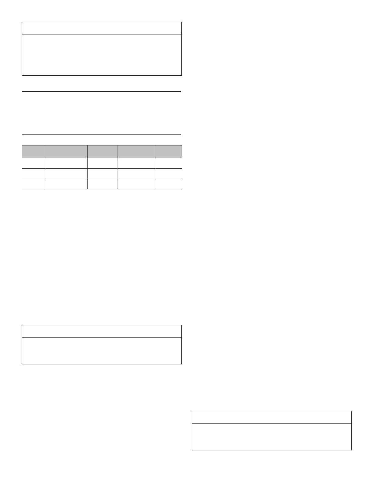
Model Volt Circuit Frequency Phase
30'' 240/208 VAC 40 Amps 60 Hz. Single
36'' 240/208 VAC 40 Amps 60 Hz. Single
48'' 240/208 VAC 50 Amps 60 Hz. Single
Table 2: Electrical Supply Circuit Requirements
WARNING
An improper 240/208 VAC power supply will cause
malfunction, damage to this appliance, and possibly
create a condition of shock hazard.
WARNING
Improper connection of aluminum house wiring can
result in a fire or shock hazard. Use only connectors
designed and certified for connecting to aluminum wire.
Installation Instructions English 17
4-Wire Connection
A unit must be connected to the power supply with a 3-
POLE, 4-CONDUCTOR cord kit rated 125/250 VOLTS, 50
AMPERES DEDICATED CIRCUIT, and marked for use
with ranges.
The cord kit must be attached to the range terminal block
with a strain relief (not provided) which will fit a 1"
(25.4 mm) diameter hole. If not already equipped, the cord
must also have 1/4'' (6 mm) faston closed-loop lugs
attached to the free ends of the individual conductors,
preferably soldered in place.
1. Locate the terminal block on the rear of the unit and
remove cover (see Figure 10).
2. Remove upper nuts only from the terminal block studs.
Do not remove lower nuts which secure range internal
wiring leads.
3. Mount strain relief (not provided with range) into the 1"
(25.4 mm) diameter hole in the back panel located
below the terminal block. Route wires up through strain
relief.
4. Secure the neutral, grounded wire of the supply circuit,
to the center stud of the terminal block with nut (see
Figure 11).
5. Secure the L1 (red) and L2 (black) power leads to the
outside terminal studs (brass colored) with nuts.
6. Remove green ground screw located beneath the
terminal block. Discard white wire.
7. Secure the bare copper ground lead to the range
chassis using the ground screw previously used for the
white wire. Be sure that neutral and ground terminals
do not touch.
8. Tighten all connections securely.
9. Reinstall the terminal block cover.
INSTALLER — show the owner the location of the circuit
breaker. Mark it for easy reference.
3-Wire Lead Connection
Where local codes and ordinances permit grounding
through neutral, and conversion of supply to 4 wire is
impractical, unit may be connected to the power supply
with a 3-POLE, 3-CONDUCTOR cord kit rated 125/250
VOLTS, 50 AMPERES DEDICATED CIRCUIT, and marked
for use with ranges.
The cord kit must be attached to the range back panel with
a strain relief which will fit a 1" (25.4 mm) diameter hole. If
not already equipped, the cord must also have 1/4'' (6 mm)
faston closed-loop lugs attached to the free ends of the
individual conductors, preferably soldered in place.
1. Locate the terminal block on the rear of the unit and
remove cover.
2. Remove upper nuts only from the terminal block studs.
Do not remove nuts which secure range internal wiring
leads.
Figure 10: Strain Relief Location
Strain Relief
Strain Relief
Strain Relief
Terminal Block
Terminal Block
Terminal Block
Figure 11: 4-Wire Connection
Red/L1
Wire
Black/L2
Wire
White/
Neutral Wire
Green/
Ground Wire
Installation Instructions English 18
3. Mount strain relief (not provided with range) into the 1"
(25.4 mm) diameter hole in the back panel located
below the terminal block (see Figure 12). Route wires
up through strain relief.
4. Secure the neutral, grounded wire of the supply circuit,
to the center stud (silver colored) of the terminal block
(see Figure 13).
5. Secure the L1 (red) and L2 (black) power leads to the
outside corresponding terminal block studs (brass
colored).
6. Secure one end of the mounted looped neutral wire,
located beneath terminal block, to the center stud of
the terminal block with nut and keep the other end of
the wire screwed into the back of the range.
7. Tighten nuts securely.
8. Reinstall the Terminal Block Cover.
INSTALLER — show the owner the location of the circuit
breaker. Mark it for easy reference.
STEP 7: Backguard
Installation (optional)
Installation methods will vary upon need. Before you begin
read these instructions carefully. Observe all local codes
and ordinances.
Backsplash Installation
(PA[30, 36, 48]JBS)
The Backsplash must be installed prior to installing an
overhead hood given that the hood shell covers the top
mounting screws of the Backsplash.
To protect against scratches, leave protective film on
Backsplash until after installation is complete.
If range is already installed, refer to the manufacturers
instructions to disconnect gas and power supplies. Move
range forward to gain access to rear of unit.
1. Locate and lightly mark wall studs. Wall studs are
usually installed with a 16'' or 24'' (406 or 610 mm)
space on center.
2. The height of the hood will determine the height of the
top edge of the Backsplash. The Backsplash should be
mounted so that the bottom rear edge of the hood
overlaps the Backsplash 1½'' (38 mm).
Figure 12: Strain Relief Location
Figure 13: 3-Wire Connection
Terminal Block
Terminal Block
Terminal Block
Strain Relief
Strain Relief
Strain Relief
Red/L1
Wire
Black/L2
Wire
White/
Neutral Wire
Ground link
provided on range
Model 30'' 36' 48''
Flush Island Trim Included Included Included
9" Low Back PA30GLBH PA36GLBH PA48GLBH
Table 3: Backguard Kit Model Numbers
PARTS INCLUDED TOOLS NEEDED
10 – 1'' (25.4 mm)
screws
Phillips screwdriver or
drill
1 – Backsplash Tape measure
WARNING
To reduce the risk of fire or injury to persons, check to
make sure all packaging has been removed from
accessory devices before use.
Installation Instructions English 19
3. Per each wall stud, use (2) 1'' (25.4 mm) Phillips head
screws to secure both the top and bottom of the
Backsplash (see Figure 14). Space screws evenly
across top and bottom of Backsplash.
Due to variable wall stud widths and varying
Backsplash widths, in some cases only one wall
stud may be found at the mounting location.
4. Remove protective plastic.
Backsplash with a Keep Hot Shelf
Installation
A hood can be installed first if the Backsplash is to be
installed with a Keep Hot Shelf given that the Keep Hot
Shelf covers the top mounting screws of the Backsplash.
To protect against scratches, leave protective film on the
Backsplash until after installation is complete.
If range is already installed, refer to the manufacturers
instructions to disconnect gas and power supplies. Move
range forward to gain access to rear of unit.
1. Locate wall studs. Wall studs are usually installed with
a 16'' (406 mm) or 24'' (610 mm) space on center.
2. The height of the hood will determine the height of the
top edge of the Backsplash. The Backsplash should be
mounted so that the bottom rear edge of the Keep Hot
Shelf overlaps the Backsplash 1½'' (38 mm).
3. At the locations indicated in Figure 16, mount the lower
shelf brackets included with the Keep Hot Shelf
through the Backsplash and into the wall studs.
Due to variable wall stud widths and varying
Backsplash widths, in some cases, only one wall
stud may be found at the mounting location.
4. Remove Backsplash protective covering.
5. Start with the Keep Hot Shelf Installation.
Figure 14: Backsplash Installation
Figure 15: Backsplash with a Keep Hot Shelf
42” (1067 mm)
30”, 36”, 48”
(762, 914, 1219 mm)
Figure 16: Backsplash with a Keep Hot Shelf
  • Page 1 1
  • Page 2 2
  • Page 3 3
  • Page 4 4
  • Page 5 5
  • Page 6 6
  • Page 7 7
  • Page 8 8
  • Page 9 9
  • Page 10 10
  • Page 11 11
  • Page 12 12
  • Page 13 13
  • Page 14 14
  • Page 15 15
  • Page 16 16
  • Page 17 17
  • Page 18 18
  • Page 19 19
  • Page 20 20
  • Page 21 21
  • Page 22 22
  • Page 23 23
  • Page 24 24
  • Page 25 25
  • Page 26 26
  • Page 27 27
  • Page 28 28
  • Page 29 29
  • Page 30 30
  • Page 31 31
  • Page 32 32
  • Page 33 33
  • Page 34 34
  • Page 35 35
  • Page 36 36
  • Page 37 37
  • Page 38 38
  • Page 39 39
  • Page 40 40
  • Page 41 41
  • Page 42 42
  • Page 43 43
  • Page 44 44
  • Page 45 45
  • Page 46 46
  • Page 47 47
  • Page 48 48
  • Page 49 49
  • Page 50 50
  • Page 51 51
  • Page 52 52
  • Page 53 53
  • Page 54 54
  • Page 55 55
  • Page 56 56
  • Page 57 57
  • Page 58 58
  • Page 59 59
  • Page 60 60
  • Page 61 61
  • Page 62 62
  • Page 63 63
  • Page 64 64
  • Page 65 65
  • Page 66 66
  • Page 67 67
  • Page 68 68
  • Page 69 69
  • Page 70 70
  • Page 71 71
  • Page 72 72
  • Page 73 73
  • Page 74 74
  • Page 75 75
  • Page 76 76
  • Page 77 77
  • Page 78 78
  • Page 79 79
  • Page 80 80
  • Page 81 81
  • Page 82 82

Thermador PRD366GHU Guide d'installation

Catégorie
Cuisinières
Taper
Guide d'installation
Ce manuel convient également à