CAME F500 - F510 Le manuel du propriétaire
- Taper
- Le manuel du propriétaire

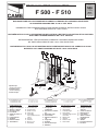
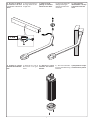
Composition set:
1 - Groupe mo-
toréducteur
2 - Armoire de comman-
de
3 - Récepteur radio
4 - Photocellule
5 - Sélecteur externe a
clé
6 - Clignotant
7 - Antenne
8 - Serrure électrique
9 - Emetteur
Das Montageset enthält:
1 - Antriebsmotor
2 - Steuergerät
3 - Funkempfänger
4 - Photozellen
5 - Außenmontage-Schlüs-
selschalter
6 - Blinkleuchte
7 - Antenne
8 - Elektroschloß
9 - Funksender
Composición set:
1 - Conjunto motorre-
ductores
2 - Cuadro de mando
3 - Radioreceptor
4 - Fotocélules
5 - Selector exterior
mediante llave
6 - Lámpara
7 - Antena
8 - Cerradura eléctrica
9 - Trasmisor
Set composition:
1 - Gear motor unit
2 - Control panel
3 - Radio receiver
4 - Photocells
5 - Protruding
key-operated selector
switch
6 - Flasher
7 - Antenna
8 - Electric lock
9 - Transmitter
Composizione set:
1 - Gruppo motoriduttore
2 - Quadro comando
3 - Ricevitore radio
4 - Fotocellule
5 - Selettore esterno a
chiave
6 - Lampeggiatore
7 - Antenna
8 - Elettroserratura
9 - Trasmettitore
Impianto tipo
Standard installation
Installation type
Standard Montage
Instalación tipo
MOTORIDUTTORE PER L'AUTOMAZIONE DI CANCELLI PEDONALI E/O CARRABILI A BATTENTE
DI LARGHEZZA MASSIMA FINO A 1.60 m. PER ANTA
GEARMOTOR FOR POWERING PEDESTRIAN AND/OR DRIVEWAY GATES HAVING WINGS
WITH MAXIMUM WIDTH OF 1.60 m. EACH
MOTORÉDUCTEUR POUR L'AUTOMATISATION DE PORTAILS A BATTANT POUR PIETONS ET/OU VOITURES
AYANT UNE LARGEUR MAXIMALE DE 1.60 m. CHACUN
GETRIEBEMOTOR FÜR DEN ANTRIEB EINGANGS- UND/ODER EINFAHRTSTOREN
MIT EINER HÖCHSTBREITE VON 1.60 m. PRO TORFLÜGEL
MOTORREDUCTOR PARA LA AUTOMATIZACION DE PUERTAS PEATONALES Y/O CARRILES A HOJAS
BATIENTES DE LONGITUD MAXIMA DE HASTA 1.60 m. CADA HOJA
Câbles d'alimentation moteur:
2 x 1.5 mm
2
jusqu'à 20 m
2 x 2.5 mm
2
jusqu'à 30 m
Antriebsmotor-Verbindungskabel:
2 x 1.5 mm
2
bis 20 m
2 x 2.5 mm
2
bis 30 m
Cables de alimentación motores:
2 x 1.5 mm
2
hasta 20 m
2 x 2.5 " " 30 m
Power wires to motor:
2 x 1.5 mm
2
up to 20 m
2 x 2.5 mm
2
up to 30 m
Cavi di alimentazione motori:
2 x 1.5 mm
2
no a 20 m
2 x 2.5 mm
2
no a 30 m
*2 x 1,5
F 500 - F 510
SERIE FLEX | FLEX SERIES | SÊRIE FLEX | BAUREIHE FLEX | SERIE FLEX
Documentazione
Tecnica
S56
rev. 2.0
del 01/04
©
CAME
CANCELLI
AUTOMATICI
119DS56
6
7
4
1
4
8
9
2 x 1
2 x 1
2 x 1
3 x 1,5 / 230V
4 x 1
2 x 1,5
RG58
3
* 2 x 1,5
TX
RX
2
5
La page charge ...
La page charge ...

4
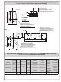
1) Tracciare gli assi e gli
ingombri dell’insieme
tenendo conto degli
schemi alle pag. 2 e
3, quindi fissare la
flangia di ancoraggio
del motoriduttore al
muro o al pilastro e, per
il motoriduttore F 500, il
supporto di ancoraggio
al cancello.
F500
F510
F500
1) Trace the centre lines
and external dimensions
of the entire assembly
in accordance with the
diagrams on pages 2
and 3.
Next, mount the flange
for the gear motor on the
wall or pillar, and mount
the anchor block for gear
motor F500 on the gate.
1) Tracer les axes et
les encombres de
l’ensemble en se
référant aux schémas de
page 2 et 3, puis xer la
bride du motoréducteur
au mur ou au pilier. Pour
le motoréducteur F500,
fixer le support de
xation au portail.
1) Die Achsen und
Außenabmessungen
der Antriebseinheit
unter Berücksichtigung
der schematischen Dar-
stellungen auf Seite 2 und
3 aufreißen und dann den
Getriebe-motor-Flansch
an der Wand oder am
Pfosten befestigen und,
bei Verwedung des
Getrie-bemotor F500, die
entsprechende Befesti-
gungsvorrichtung am Tor
anbringen.
1) Trazar los ejes y
las dimensiones del
conjunto tenendo en
cuenta los esquemas
de pág. 2 y 3,poste-
riormente jar la brida
del motorreductor a la
pared o al pilar y, para
el motorreductor F500,
el soporte de enclje a la
puerta.
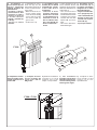
2) Assemblare il braccio
snodato unendo i
due semibracci con
l’apposita bulloneria.
2) Use the hardware
provided with the unit to
join the two halves of the
articulated arm together.
2) Assembler le bras
articulé en reliant les
deux demibras avec la
boulonnerie prèvue à
cet effet.
2) Die beiden GelenKar-
mhälften mit den mit-
gelieferten Schrauben
zusammenfügen
2) Ensamblar el brazo
articulado uniendo
los semibrazos
con los pernos
correspondientes
ISTRUZIONI DI MONTAGGIO | ASSEMBLY INSTRUCTIONS | INSTRUCTIONS POUR LE MONTAGE
MONTAGEANLEITUNG | INSTRUCCIONES DE MONTAJE

5
F 510
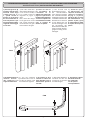
3) Fissare la guida di
scorrimento all'anta
e inserire il braccio
dritto.
4) Togliere la calotta
inferiore dal motoridut-
tore.
4) Enlever les carter
inférieur du motoré-
ductéur.
4) Desplazar el casque-
te inferior de la puerta.
4) Die untere Getriebe-
motor-Schutzabdeckung
entfernen.
4) Remove the cover at
the bottom of the gear
motor.
3) Secure the runner to
the wing and insert the
straight arm.
3) Fixer le rail de
guidage au vantail et
monter le bras droit.
3) Die Laufschiene am
Türügel befestigen
und den geraden Arm
einführen.
3) Fije la guía de
deslizamiento a la hoja
e introduzca el brazo
recto.

6
5) Fissare il motori-
duttore alla flangia
mediante le quattro viti
in dotazione.
- Fissare la calotta su-
periore.
5) Using the four screws
provided with the unit,
install the gear motor on
the ange.
- Fix the upper cap.
5) Fixer le
motoréducteur à la
bride à l’aide des
quatre vis fournies.
- Fixer la calotte
supérieure.
5) Den Getriebemotor
mit den vier zum
Lieferumfang gehörenden
Schrauben am Flansch
befestigen.
- Die obere Gehäuse-
hälfte Befestigen.
5) Fijar el motor-re-
ductor a la brida me-
diante los quatro tornil-
los suministrados.
- Fije la tapa superior.
6) Assemblare il brac-
cio snodato (A) alla
boccola intermedia
solidale all’albero del
motoriduttore;
- Fissare la staffa sul
cancello con l’appo-
sita bulloneria;
- Eseguire il collega-
mento elettrico, dare
tensione al motori-
duttore in chiusura e
ssare il braccio tra-
mite il grano M6 (B);
- Fissare la calotta in-
feriore.
6) Assemble the articu-
lated arm (A) onto the
intermediate bush which
is all in one with the ratio-
motor shaft;
- Using the hardware
provided with the unit,
install the bracket on
the gate;
- Make the electrical con-
nection, supply voltage
to the ratio-motor during
closure and secure the
arm with the M6 (B)
grub screw;
6) Assembler le bras
articulé (A) à la douille
intermédiaire solidai-
re de l’arbre du mo-
toréducteur;
- Fixer l’étrier sur le
portail avec la bou-
lon-nerie prévue à cet
effet ;
- Effectuer le bran-
chement électrique,
donner de la tension
au motoréducteur en
fermeture et fixer le
bras à l’aide du boulon
sans tête M6 (B);
- Fixer la calotte infé-
rieure.
6) Den Gelenkarm (A)
an der mittleren Buchse
anbringen, die fest mit der
Welle vom Getriebemotor
verbun-den ist.
- Den Bügel mit den ents-
prechenden Schrauben
am Tor befestigen.
- Den Stromanschluß
durchführen, den Strom
am Getriebemotor beim
Schließen einschalten
und den Arm mit dem
Zapfen M6 (B) befes-
tigen.
- Die untere Gehäuse-
hälfte Befestigen.
6) Ensamble el bra-
zo articulado (A) al
casquillo intermedio
integrado con el árbol
del motorreductor;
- Fijar el estribo a la
puerta con los tornil-
los correspondien-
tes;
- Haga la conexión eléc-
trica, ponga bajo ten-
sión el motorreductor
durante el cierre y
fije el brazo con el
pasador M6 (B);
- Fije la tapa inferior.
B
F 500
ø 3,5 x 9,5
A
ø 3,9 x 13

7
8) completare l’installa-
zione ssando il coper-
chietto superiore con il
relativo OR.
8) Complete instal-la-
tion by mounting the
upper cover with its
OR gasket.
8) Terminer l’instal-lation
en fixant le cou-vercle
supérieur avec le joint
torique correspon-dant.
8) Completar la insta-
lación fijando la tapa
superior con el corre-
spondiente OR.
7) Assemblare il
braccio diritto (D) alla
boccola intermedia
solidale all’albero del
motoriduttore;
- Eseguire il collega-
mento elettrico, dare
tensione al motori-
duttore in chiusura
e fissare il braccio
tramite i grani M8 (C)
e M4 (E);
- Fissare la calotta
inferiore.
8) Die Installation
beenden und die obere
Abdeckung mit entspre-
chender Rund-gummi-
dichtung befe-stigen.
7) Assemble the articu-
lated arm (D) onto the
intermediate bush which
is all in one with the ratio-
motor shaft;
- Make the electrical con-
nection, supply voltage
to the ratio-motor during
closure and secure the
arm with the M6 (C)
grub screws;
- Fix the lower cap.
7) Assembler le bras
articulé (D) à la douille
intermédiaire solidai-
re de l’arbre du mo-
toréducteur;
- Effectuer le bran-
chement électrique,
donner de la tension
au motoréducteur en
fermeture et fixer le
bras à l’aide des bou-
lons sans tête M6 (C);
- Fixer la calotte infé-
rieure.
7) Den Gelenkarm (D)
an der mittleren Buchse
anbringen, die fest mit der
Welle vom Getriebemotor
verbun-den ist.
- Den Stromanschluß
durchführen, den Strom
am Getriebemotor beim
Schließen einschalten
und den Arm mit dem
Zapfen M6 (C) befes-
tigen.
- Die untere Gehäuse-
hälfte Befestigen.
7) Ensamble el bra-
zo articulado (D) al
casquillo intermedio
integrado con el árbol
del motorreductor;
- Haga la conexión eléc-
trica, ponga bajo ten-
sión el motorreductor
durante el cierre y je
el brazo con las pasa-
dores M6 (C);
- Fije la tapa inferior.
F 500 - F 510
OR
F 510
D
C
C
E
E
La page charge ...
-
 1
1
-
 2
2
-
 3
3
-
 4
4
-
 5
5
-
 6
6
-
 7
7
-
 8
8


CAME F500 - F510 Le manuel du propriétaire
- Taper
- Le manuel du propriétaire
dans d''autres langues
- italiano: CAME F500 - F510 Manuale del proprietario
- English: CAME F500 - F510 Owner's manual
- español: CAME F500 - F510 El manual del propietario
- Deutsch: CAME F500 - F510 Bedienungsanleitung
Documents connexes
-
CAME FLEX 119RID158 Le manuel du propriétaire
-
-
-
-
-
-
-
-
CAME EMEGA Standard Installation
-