ASA Electronics 7396051 Le manuel du propriétaire
- Catégorie
- Radios
- Taper
- Le manuel du propriétaire
Ce manuel convient également à

7159873/7396051
Owner’s Manual*
Guide du propriétaire**
* These instructions apply to Bobcat model 7159873 and 7396051 mobile audio systems.
** Ces instructions s'appliquent aux systèmes audio mobiles du model 7159873 et 7396051de Bobcat.
P/N: 37200046


7159873/7396051
2
Thank You!
Thank you for choosing a Bobcat product. We hope you will find the instructions in this owner’s manual
clear and easy to follow. If you take a few minutes to look through it, you’ll learn how to use all the
features of your new Bobcat receiver for maximum enjoyment.
System Features . . . . . . . . . . . . . . . . . . . . . . . . . . . . . . . . . . . . . . . . . . . . . . . . . . . . . . . . . . . . . . . . 3
Installation . . . . . . . . . . . . . . . . . . . . . . . . . . . . . . . . . . . . . . . . . . . . . . . . . . . . . . . . . . . . . . . . . . . . . 5
Wiring. . . . . . . . . . . . . . . . . . . . . . . . . . . . . . . . . . . . . . . . . . . . . . . . . . . . . . . . . . . . . . . . . . . . . . . . . 7
Basic Operation. . . . . . . . . . . . . . . . . . . . . . . . . . . . . . . . . . . . . . . . . . . . . . . . . . . . . . . . . . . . . . . . . 8
Tuner Operation . . . . . . . . . . . . . . . . . . . . . . . . . . . . . . . . . . . . . . . . . . . . . . . . . . . . . . . . . . . . . . . 10
Weather Band Operation . . . . . . . . . . . . . . . . . . . . . . . . . . . . . . . . . . . . . . . . . . . . . . . . . . . . . . . . .11
Troubleshooting . . . . . . . . . . . . . . . . . . . . . . . . . . . . . . . . . . . . . . . . . . . . . . . . . . . . . . . . . . . . . . . .12
Specifications . . . . . . . . . . . . . . . . . . . . . . . . . . . . . . . . . . . . . . . . . . . . . . . . . . . . . . . . . . . . . . . . . .13
Merci!
Merci d'avoir choisi un produit par Bobcat. Nous espérons que vous trouverez les instructions
dans ce guide du propriétaire facile à suivre. On vous encourage à le lire pour que vous appre-
niez comment utiliser toutes les fonctions de votre nouveau récepteur Bobcat pour vous amus-
er au maximum.
Fonctions du système . . . . . . . . . . . . . . . . . . . . . . . . . . . . . . . . . . . . . . . . . . . . . . . . . . . . . . . . . . 15
Installation . . . . . . . . . . . . . . . . . . . . . . . . . . . . . . . . . . . . . . . . . . . . . . . . . . . . . . . . . . . . . . . . . . . . 17
Câblage . . . . . . . . . . . . . . . . . . . . . . . . . . . . . . . . . . . . . . . . . . . . . . . . . . . . . . . . . . . . . . . . . . . . . . 19
Opération de base. . . . . . . . . . . . . . . . . . . . . . . . . . . . . . . . . . . . . . . . . . . . . . . . . . . . . . . . . . . . . . 20
Opération Tuner . . . . . . . . . . . . . . . . . . . . . . . . . . . . . . . . . . . . . . . . . . . . . . . . . . . . . . . . . . . . . . . 22
Opération Weather Band . . . . . . . . . . . . . . . . . . . . . . . . . . . . . . . . . . . . . . . . . . . . . . . . . . . . . . . . .23
Dépannage. . . . . . . . . . . . . . . . . . . . . . . . . . . . . . . . . . . . . . . . . . . . . . . . . . . . . . . . . . . . . . . . . . . . .24
Spécifications . . . . . . . . . . . . . . . . . . . . . . . . . . . . . . . . . . . . . . . . . . . . . . . . . . . . . . . . . . . . . . . . . .25

7159873/7396051
3
Features
Features of the Bobcat 7159873/7396051 mobile audio system include:
• Waterproof
• uV and Corrosion Resistant
• Electronic US/Euro AM/FM Tuner
• 30 Programmable Presets (12 AM, 18 FM)
• Non-Volatile Memory for User Settings and Preset Memories
• 7-Channel NOAA Weather Band
• Weather Alert
• Auxiliary Audio Input
• Headphone Output
• 2-Channel Amplified Audio Output
• Backlit Controls with Selectable Illumination Color
• Daylight Readable Display
• Clock with 30-day Backup Power
•Work Timer
• Audible Beep ConfirmationTone

7159873/7396051
4
Machine Screws
wit
h Nuts (3)
M4 Machine
Screws (4)
Self-Tapping
Screws (3)
Washers (5)
Bobcat 7159873 Radio
Wiring Harness
Radio
Mounting Bracket
Headphone
Mounting Bracket
Self-Tapping
Screws (2)
Machine Screws
with Nuts (2)
Auxiliary Input
Patch Cord
Owner’s Manual
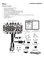
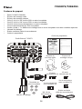
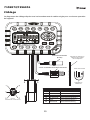
Package Contents
• Bobcat 7159873/7396051 Radio
• Radio Mounting Bracket
• Headphone Mounting Bracket
• Five (5) 10-16 x 3/4” Stainless Steel PPH Screws
• Five (5) 10-32 x 5/8” Stainless Steel PPH Screws
• Five (5) 10-32 Stainless Steel Hex Nuts
• Five (5) #10 Stainless Steel Washers
• Four (4) M4 x .7 x 8MM Stainless Steel Hex Screws with Captivated Washers
• Wiring Harness
• Auxiliary Input Patch Cord
• Owner’s Manual

7159873/7396051
5
Regular
Mounting
Overhead
Mounting
Machine Screws
with Nuts
Self-Tapping
Screws
(Hole size 7/32")
(Hole size 7/32")
Mounting machine screw
Bracket metal
Vehicle mounting surface
Washer
Nut
Mounting Stack
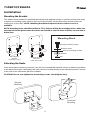
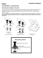
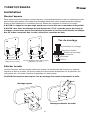
Installation
Mounting the Bracket
Two options are provided for mounting the bracket (self-tapping screws or machine screws with nuts)
to ensure a mounting option ideal for your mounting location. Avoid obstructing airflow to the rear
cooling fins on the radio. NOTE: Mounting bracket not required when custom console is
available.
NOTE: Mounting holes should be drilled to 7/32”. Before drilling the mounting holes, make sure
the area behind the panel where the holes are desired is clear of wires and fuel, vacuum and or
brake lines.
Attaching the Radio
Once the bracket is securely mounted, use the four included M4 machine screws to fasten the bracket
to the back of the radio. Alternately, the radio can be mounted directly to the instrument panel if access
to the rear of the instrument panel is available.
CAUTION! Do not over tighten the 4 mounting screws. Hand tighten only.

7159873/7396051
6
Machine Screws
with Nuts
Double-Sided
Tape
(Hole size 7/32")
(Hole size 7/32")
Self-Tapping
Screws
Mounting machine screw
Bracket metal
Vehicle mounting surface
Washer
Nut
Mounting Stack
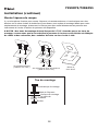
Installation (continued)
Mounting the Headphone Bracket
Three options are provided for mounting the bracket (self-tapping screws, machine screws with nuts or
double-sided tape) to ensure a mounting option ideal for your mounting location. Alternately, the
headphone can be mounted directly to the instrument panel if access to the rear of the instrument
panel is available.
NOTE: Mounting holes should be drilled to 7/32”. Before drilling the mounting holes, make sure
the area behind the panel where the holes are desired is clear of wires and fuel, vacuum and or
brake lines.

7159873/7396051
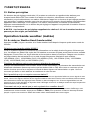
7
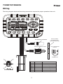
EXTERNAL ANTENNA
3.5mm STEREO JACK
RED
BLACK
WHITE
WHITE/BLACK
GRAY
GRAY/BLACK
SWITCHED POWER 12V (+)
GROUND 12V (-)
LEFT SPEAKER (+)
LEFT SPEAKER (-)
RIGHT SPEAKER (+)
RIGHT SPEAKER (-)
PIN NO. WIRE COLOR DESCRIPTION
3.5mm HEADPHONE
OUTPUT
RUBBER CAP
NUT
WASHER
VEHICLE PANEL
OR HEADPHONE
MOUNTING BRACKET
Wiring
The wiring diagram depicts all the wiring connections required for proper operation of the unit.

7159873/7396051
8
10
36214
5a
7a
7a
9
5b
11a
11b
12a
12b
13
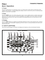
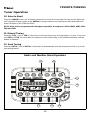
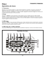
Basic Operation
1. Power
Press the power button (1) to turn the unit on or off. This button is also used to access the version
number of the software. To briefly display the software version on the LCD, press and hold the power
button for more than five seconds.
2. Mute
Press the MUTE button (2) to silence the audio output in tuner, weather band or auxiliary input mode.
When the audio output is silenced, “MUTE” will appear in the display. If the mute feature is activated
when the unit is turned off, the volume will default to the programmed turn-on level when the unit is
turned back on.
3. Display
Press the DISP button (3) to toggle the LCD display between function mode (showing tuner, auxiliary
input or weather band information, depending on which mode is currently activated) and clock mode
(showing the time).
4. Liquid Crystal Display
The Liquid Crystal Display (LCD) panel (4) displays the frequency, time and activated functions.
Basic Operation

7159873/7396051
9
5. Auxiliary Input Function
To connect a portable audio device (MP3 player, iPOD, etc.) to the 7159873/7396051, connect the headphone or
line level output of the device to the 1/8" auxiliary input jack (5b) on the 7159873/
7396051 using the audio patch
cord (included). Press the
AUX
button (5a) to select auxiliary input mode.
NOTE: The 7159873/7396051 also comes equipped with a 3.5mm headphone jack (see “Wiring” on page 7)
that when connected to headphones, will mute the external speakers and play audio through the headset.
6. Timer
Press the
TIMER
button (6) to access timer mode and start the timer function. The “TIMER” icon will flash in the
display. Press
TIMER
again to stop the timer. The “TIMER” icon will remain in the display but will no longer flash.
Press the button again to resume the timer, or press and hold for three seconds to reset the timer to zero and
remove the “Timer” icon from the display.
7. Volume
Press the
VOL+
(7a) or
VOL-
(7b) button to adjust the volume up or down one step. Press and hold
VOL+
or
VOL-
for more than one second to continuously adjust the volume level until the button is released. The current
volume level (0 to 40) appears in the display when the volume is adjusted, returning to the default display three
seconds after the adjustment is complete.
8. Setting the Clock
To set the clock to display the current time, press the
DISP
button (3) for more than three seconds to enter clock
setting mode, and the time will flash in the display. Press
TUN-
(11a) to adjust the hours or
TUN+
(11b) to adjust
the minutes. When no adjustment is made for ten seconds, the time sets and normal operation resumes.
9. Audio and Menu Adjustment
Audio Adjustment
Press the AUDIO/MENU button (9) to step through the following audio adjustment options: Bass,
Treble and Balance (left to right). When the desired option appears in the display, press VOL+ (7a) or
VOL- (7b) to adjust that audio feature. When no adjustments have been made for three seconds, the
unit will resume normal operation.
Menu Adjustment
Press AUDIO/MENU for more than three seconds to enter menu adjustment mode and adjust any of
the menu options: When the desired option appears in the display, press VOL+ or VOL- to adjust that
menu option. When no adjustments have been made for three seconds, the unit will resume normal
operation. The following menu options may be adjusted using this feature:
• Beep Confirm (On or Off
) - Determines if a beep will be heard each time a button is pressed.
• Operation Region (USA
or Euro) - Selects the appropriate operating region.
• Clock Display (12
or 24) - Selects a 12-hour or 24-hour clock display.
• Display Brightness (Low, Mid or High
) - Determines brightness level of the display.
• Backlight Color (Amber
or Green) - Determines the backlight color of the unit.
• P-VOL [Power on Volume] (On or Off
) - Determines if preset Turn On Volume will be set.
• Turn On Volume (0-40) - Selects desired volume level for the unit to assume when turned on.
• WB Alert (On or Off
) - Determines if the weather band alert feature is activated.
• Default - Select to return to factory default settings.
NOTE: Underlined option denotes the default setting.

7159873/7396051
10
10
11a
11b
12a
12b
13
14
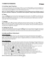
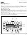
Tuner Operation
10. Select a Band
Press the AM/FM button (10) to directly access tuner mode from any other function mode. When the
unit is already in tuner mode, press AM/FM to change between two AM bands (AM1 and AM2) and
three FM bands (FM1, FM2 and FM3).
NOTE: If the unit is programmed for European operation, the sequence will be MW1, MW2, FM1,
FM2 and FM3.
11. Manual Tuning
Press the TUN- (11a) or TUN+ (11b) button to tune the frequency one step higher or lower. Press and
hold TUN+ or TUN- for more than one second to tune continuously in the selected direction until the
button is released.
12. Seek Tuning
Press the SEEK- (12a) or SEEK+ (12b) button to automatically tune the frequency down or up to the
next strong station.
Radio and Weather Band Operation

7159873/7396051
11
13. Preset Stations
Six numbered preset buttons (13) store and recall stations for each AM and FM band. To store a
station, select a band (if needed), then select a station. Press and hold a preset button for three
seconds. The current station is stored and the corresponding preset number appears in the display. To
recall a station, select a band (if needed) and then press a preset button to tune to the corresponding
stored station.
NOTE: Preset buttons recall channels 1-6 on weather band and cannot be set by the user.
Weather Band Operation
14. Accessing the Weather Band
Press the WB button (14) to directly access the weather band mode from any other function mode.
What is the NOAA Weather Radio?
This is a nationwide system that broadcasts local weather emergency information 24 hours a day. The U.S.
network has more than 530 stations covering the 50 states as well as the adjacent costal waters, Puerto Rico,
the U.S. Virgin Islands and the U.S. Pacific Territories. Each local area has its own transmitting station and
there are a total of seven broadcasting frequencies used: 162.400MHz (CH1), 162.425MHz (CH2),
162.450MHz (CH3), 162.475MHz (CH4), 162.500MHz (CH5), 162.525MHz (CH6) and 162.550MHz (CH7).
How many stations can I expect to receive?
Since the broadcasts are local weather and information, the transmission power is usually very low (much
less than AM or FM stations) so you will usually receive only one station unless you are on the edge of two or
more broadcast signals. The most you will receive will be two or three, and that is rare.
Is it possible I won't receive any stations?
Depending on location, it’s possible you will receive a very weak signal or none at all. Also, similar to AM and
FM signals, weather band signals are subject to surrounding conditions, weather, obstructions of the signal
by hills or mountains, etc. If no NOAA signals are found/received, the “NO SIG” icon will flash in the display
and the tuner will scan all seven NOAA frequencies every 30 seconds.
How will I know I am tuned to the weather band?
When you select the weather band, the “WB” icon will appear on the display panel, along with the current
channel indication. Press TUN+ or TUN- to tune to each of the seven channels until you find the weather
band station broadcasting in your area.
NOAA Weather Alert
The Weather Alert function adds an additional level of user safety by automatically switching from the current
function mode to weather band mode for a minimum of 60 seconds if a NOAA warning tone (1050 Hz) is
received/detected. If no additional warning tone is received for 60 seconds, the unit will switch back to the last
known function mode.
The Weather Alert function can be turned “on” or “off” by the Audio/Menu key, as described on page three.
When “ON” (default), the Weather Alert icon appears in the display and the weather tuner remains active,
even when the radio is turned off (as long as the power is still applied to the radio). If a weather alert is issued,
the radio will turn on and play the announcement. for 60 seconds, then turn back off and revert to weather
alert monitor mode.
If the Weather Alert function is set to “OFF”, no Weather Alert icon appears in the display. The radio will not
respond to any weather alerts when it is off and will not automatically switch to the weather band if an alert is
issued.
NOTE: If the unit is programmed for European operation, the WB function is disabled.

7159873/7396051
12
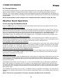
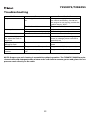
Troubleshooting
NOTE: Proper care and cleaning is essential to optimal operation. The 7159873/7396051 may be
cleaned with mild detergent/water mixture and a soft cloth to remove grease and grime. Do not
pressure wash directly on the radio.
Problem Cause Corrective Action
No power. Vehicle ignition switch is not
on.
If the power supply is connected to
the vehicle accessory circuits but
the engine is not moving, switch the
ignition key to “ACC”.
The 3A fuse is blown. Replace the 3A fuse.
No reception Volume turned down too low. Adjust volume until sound is heard.
Wiring not connected properly. Check wiring connections.
Radio does not work Antenna cable not connected. Insert antenna cable firmly.
Volume too high or too
low when the radio is
turned on
Preset volume is set incorrectly Use the Menu adjustment (page
three) to change preset volume to
desired level
LCD display is dark and
difficult to read
Radio too hot Turn radio off and allow to cool
down
No WB function Programmed to “European” Program to “USA” (setup menu)
Weather alert does not
function
Weather alert programmed to
“off”
Program to “on” (setup menu)

7159873/7396051
13
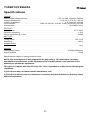
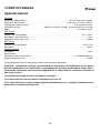
Specifications
General
Power Supply Requirements . . . . . . . . . . . . . . . . . . . . . . . . . . . . . . . DC 12 Volts, Negative Ground
Chassis Dimensions . . . . . . . . . . . . . . . . . . . . . . . . . . . . . . . . . . . . . . 131.6 (W) x 47.5 (D) x 86 (H)
Loading Impedance . . . . . . . . . . . . . . . . . . . . . . . . . . . . . . . . . . . . . . . . . . . . 4 -8 ohms per channel
Tone Controls . . . . . . . . . . . . . . . . . . . . . . . . Bass (at 100 Hz), ±10 dB; Treble (at 10 kHz), ±10 dB
Current Drain . . . . . . . . . . . . . . . . . . . . . . . . . . . . . . . . . . . . . . . . . . . . . . . . . . . . . 1.5 Ampere (max)
FM Tuner
Tuning range . . . . . . . . . . . . . . . . . . . . . . . . . . . . . . . . . . . . . . . . . . . . . . . . . . . . . . . . . . .87.5-108.0
FM mono sensitivity. . . . . . . . . . . . . . . . . . . . . . . . . . . . . . . . . . . . . . . . . . . . . . . . . . . . . . . . . .1.5uV
Stereo separation @ 1 kHz . . . . . . . . . . . . . . . . . . . . . . . . . . . . . . . . . . . . . . . . . . . . . . . . . . . >25dB
AM Tuner
Tuning range . . . . . . . . . . . . . . . . . . . . . . . . . . . . . . . . . . . . . . . . . . . . . . . . . . . . . . . . . . . .522-1710
Sensitivity . . . . . . . . . . . . . . . . . . . . . . . . . . . . . . . . . . . . . . . . . . . . . . . . . . . . . . . . . . . . . . . . <30uV
Weather Band
Sensitivity . . . . . . . . . . . . . . . . . . . . . . . . . . . . . . . . . . . . . . . . . . . . . . . . . . . . . . . . . . . . . . . . . <1uV
Amplifier
Total system power . . . . . . . . . . . . . . . . . . . . . . . . . . . . . . . . . . . . . . . . . . . . . . 15 Watts Maximum
Signal to Noise . . . . . . . . . . . . . . . . . . . . . . . . . . . . . . . . . . . . . . . . . . . . . . . . . . . . . . . . . . . . >70dB
Specifications subject to change without notice.
NOTE: The manufacturer is not responsible for any radio or TV interference caused by
unauthorized modifications to this equipment. Such modifications could void the User’s
authority to operate the equipment.
This device complies with Part 15 of the FCC rules. Operation is subject to the following two
conditions:
1) This device may not cause harmful interference, and
2) This device must accept any interference received, including interference that may cause
undesired operation.

7159873/7396051
14

7159873/7396051
15
Fonctions
Les fonctions du système audio portatif Bobcat 7159873/7396051 comprennent :
• Etanchéité
• Résistant aux rayons ultra-violet et la corrosion
• Electronique US/Euro Tuner AM/FM
• 30 pré-réglés programmables (12 AM, 18 FM)
• Mémoire non-volatile pour des réglages d'utilisateur et des mémoires des pré-réglés
• NOAA Weather Band à 7-Chaînes
•Alerte météo
• Entrée audio auxiliaire
• Sortie casque
• Sortie audio amplifié à 2-Chaînes
• Des contrôles rétroéclairés avec une illumination en couleur sélectionnable
• Affichage lisible pendant la journée
• Horloge avec puissance en réserve pour 30 jours
• Minuterie travail
• Tonalité de confirmation bip audible

7159873/7396051
16
M4 Vis de
mécanique (4)
Vis auto-
taraudeuses (3)
Vis de mécanique
avec rondelles (3)
Radio Bobcat 7159873
Harnais de câblage
Equerre de
montage radio
Equerre de
montage casque
Vis auto-
taraudeuses (2)
Vis de mécanique
(2)avec rondelles
Entrée auxiliaire
câble de raccordement
Guide du propriétaire
Rondelles en
acier inoxydable
Contenu du paquet
• Radio 7159873/7396051
• Equerre de montage radio
• Equerre de montage casque
• Cinq (5) 10-16 x 3/4" écrous PPH en acier inoxydable
• Cinq (5) 10-32 x 5/8" écrous PPH en acier inoxydable
• Cinq (5) 10-32 écrous hexagonaux en acier inoxydable
• Cinq (5) #10 Rondelles en acier inoxydable
• Quatre (4) M4 x .7 x 8MM ecrous hexagonaux en acier inoxydable avec des rondelles captivées
• Harnais de câblage
• Entrée auxiliaire câble de raccordement
• Guide du propriétaire

7159873/7396051
17
Installation
Montez l'équerre
Deux options sont fournies pour monter l'équerre (vis autotaraudeuses ou des vis mécaniques avec
des boulons) pour assure rune options de montage idéale pour votre emplacement de montage.
Evitez de faire obstacle à la circulation d'air aux ailettes de ventilation à l'arrière sur la radio.
A NOTER: Le support n'est pas exigé quand une console faite sur commande est disponible.
A NOTER : Des trous de montage doivent être percés à 7/32". Avant de percer des trous de
montage, assurez-vous que la zone derrière le panneau où les trous sont désirés est déblayé
des fils et des carburants, des circuits à vide et des conduites de frein.
Attacher la radio
Lorsque l'équerre est bien montée utilisez les quatre vis mécaniques M4 fournis pour attacher
l'équerre au dos de la radio. OU bien la radio peut être montée directement sur le panneau aux
instruments s'il y a l'accès à l'arrière du panneau aux instruments.
CAUTION! Ne resserrez pas trop les 4 vis de montage. Resserrez uniquement à la main.
Regular
Mounting
Overhead
Mounting
Vis mécaniques avec des boulons
(Taille du trou 7/32”)
Vis autotaraudeuses
(Taille du trou 7/32”)
Vis mécanique à montage
Métal de l'équerre
Surface de montage
du véhicule
Rondelle
Boulon
Tas de montage
Montage régulier
Montage au-dessus de la tête

7159873/7396051
18
Vis mécanique à montage
Métal de l'équerre
Surface de montage
du véhicule
Rondelle
Boulon
Tas de montage
Ruban à
deux faces
Vis mécaniques avec des boulons
(Taille du trou 7/32”)
Vis autotaraudeuses
(Taille du trou 7/32”)
Installation (continué)
Monter l'équerre de casque
Il y a trois options fournies pour monter l'équerre (vis autotaraudeuses, vis mécanique avec des
boulons ou du ruban isolant à double face) pour assure rune option de montage idéale pour votre
emplacement de montage. Autrement, le casque peut être monté directement au panneau aux
instruments si l'accès à l'arrière du panneau est disponible.
A NOTER : Des trous de montage doivent être percés à 7/32". Avant de percer les trous de
montage, assurez-vous que la zone derrière le panneau où les trous sont désirés est déblayée
de câbles et des carburants, des conduites de freins ou des circuits à vide.

7159873/7396051
19
Connecteur d'antenne
(fil noir)
VUE A-A
MONTRÉ DE LA VUE DE PIN
Sortie case 3.5mm
Casquette en
caoutchouc
Panneau du véhicule ou
l'équerre de montage
de la casquette
3.5mm CONNECTEUR D'ÉCOUTEUR
ROUGE
NOIR
BLANC
BLANC/NOIR
GRIS
GRIS/NOIR
PUISSANCE COMMUTÉE 12V (+)
FIL DE MASSE 12V (-)
HAUT-PARLEUR GAUCHE (+)
HAUT-PARLEUR GAUCHE (-)
HAUT-PARLEUR DROIT (+)
HAUT-PARLEUR DROIT (-)
NOMBRE COULEUR DE FIL DESCRIPTION
BOULON
RONDELLE
Câblage
Le diagramme de câblage dépeint tous les branchements de cables exigés pour une bonne operation
de l'appareil.
La page est en cours de chargement...
La page est en cours de chargement...
La page est en cours de chargement...
La page est en cours de chargement...
La page est en cours de chargement...
La page est en cours de chargement...
La page est en cours de chargement...
La page est en cours de chargement...
-
 1
1
-
 2
2
-
 3
3
-
 4
4
-
 5
5
-
 6
6
-
 7
7
-
 8
8
-
 9
9
-
 10
10
-
 11
11
-
 12
12
-
 13
13
-
 14
14
-
 15
15
-
 16
16
-
 17
17
-
 18
18
-
 19
19
-
 20
20
-
 21
21
-
 22
22
-
 23
23
-
 24
24
-
 25
25
-
 26
26
-
 27
27
-
 28
28


ASA Electronics 7396051 Le manuel du propriétaire
- Catégorie
- Radios
- Taper
- Le manuel du propriétaire
- Ce manuel convient également à
dans d''autres langues
Documents connexes
-
Voyager JHD910 Manuel utilisateur
-
-
 Jensen Heavy Duty SWJHD905 Manuel utilisateur
-
Jensen VOYAGER MCD6115 Le manuel du propriétaire
-
-
 ASA Electronics VR185 Manuel utilisateur
-
-
Voyager VOSHD4MNT Manuel utilisateur

