
Wattstopper
®
DLM - Isolated Relay Interface
Installation Instructions • Instructions d’Installation • Instrucciones de Instalación
No: 24619 – 09/16 rev. 1
Catalog Number • Numéro de Catalogue • Número de Catálogo: LMRL-100
Country of Origin: Made in China • Pays d’origine: Fabriqué en Chine • País de origen: Hecho en China
SPECIFICATIONS
Voltage ...................................................................................... 24VDC
Current Consumption .....................................................................7mA
Power Supply ......................................... Wattstopper Room Controller
Connection to the DLM Local Network ............................ 2 RJ-45 ports
Isolated relay ratings ...... 1A 24VDC/VAC, SPDT normally open (N/O),
.................................normally closed (N/C) and common outputs
Environment ..................................................For Indoor Use Only
Operating Temperature ......................... 32° to 104°F (0° to 40°C)
Storage Temperature ...........................23° to 176°F (-5° to 80°C)
Relative Humidity ...............................5 to 95% (non condensing)
Other:
RoHS compliant
UL2043 Plenum rated
This unit is pre-set for Plug n’ Go™ operation, adjustment is
optional.
For full operational details, adjustment and more features of the product,
see the DLM System Installation Guide provided with Wattstopper room
controllers, and also available at www.legrand.us/wattstopper.
Installation shall be in accordance with all applicable regulations, local
and NEC codes. Wire connections shall be rated suitable for the wire size
(lead and building wiring) employed.
For Class 2 DLM devices and device wiring: To be connected to a Class 2
power source only. Do not reclassify and install as Class 1, or Power and
Lighting Wiring.
DESCRIPTION
The LMRL-100 Isolated Relay Interface is an optional module for the Wattstopper Digital Lighting Management system (DLM) that allows
integration of third-party devices. The LMRL-100 connects to the DLM local network and activates its isolated relay upon any occpancy
signal. Connecting a third-party’s device to the LMRL-100 relay output allows the third-party device to observe when occupancy is
detected.
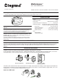
MOUNTING AND WIRING
Installation shall be in accordance with all applicable regulations, wiring practices, and codes.
To be connected to a Class 2 power source only. • Class 2 Device Wiring Only – Do Not Reclassify and Install as Class 1, 3 or Power
and Lighting Wiring. • Wire connections shall be rated suitable for the wire size (lead and building wiring) employed.
The LMRL-100 is UL2043 Plenum rated. All connections to the LMRL-100 are Class 2 low voltage. If code requires that the LMRL-100
be mounted in an enclosure, it can be mounted inside a 4” x 4” junction box, inside a 2
1
/
8
” deep (or deeper) 1-gang wall box, in a 3” or 4”
octagonal box, or on a din rail inside a building automation panel.
Attach the LMRJ Cable
Din rail clip attached Removing din rail clip Inside a 2
1
/
8
” deep
single gang wall box

800.879.8585
www.legrand.us/wattstopper
No. 24619 – 09/16 rev. 1
© Copyright 2016 Legrand All Rights Reserved.
© Copyright 2016 Tous droits réservés Legrand.
© Copyright 2016 Legrand Todos los derechos reservados.
Wattstopper warranties its products to be free
of defects in materials and workmanship for a
period of five (5) years. There are no obligations
or liabilities on the part of Wattstopper for
consequential damages arising out of, or in
connection with, the use or performance of this
product or other indirect damages with respect
to loss of property, revenue or profit, or cost of
removal, installation or reinstallation.
Wattstopper garantit que ses produits sont
exempts de défauts de matériaux et de fabrication
pour une période de cinq (5) ans. Wattstopper
ne peut être tenu responsable de tout dommage
consécutif causé par ou lié à l’utilisation ou
à la performance de ce produit ou tout autre
dommage indirect lié à la perte de propriété, de
revenus, ou de profits, ou aux coûts d’enlèvement,
d’installation ou de réinstallation.
Wattstopper garantiza que sus productos
están libres de defectos en materiales y mano
de obra por un período de cinco (5) años. No
existen obligaciones ni responsabilidades por
parte de Wattstopper por daños consecuentes
que se deriven o estén relacionados con el
uso o el rendimiento de este producto u otros
daños indirectos con respecto a la pérdida
de propiedad, renta o ganancias, o al costo
de extracción, instalación o reinstalación.
WARRANTY INFORMATION INFORMATIONS RELATIVES À LA GARANTIE INFORMACIÓN DE LA GARANTÍA
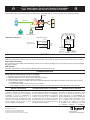
The DLM local network uses free topology low voltage wiring. The LMRL-100 can connect anywhere on the DLM local network.
Terminal Connections
LMRJ Cables
Loads
1
2
Line Voltage
Room
Controller
Occupancy Sensor
Switch
LMRL-100
Isolated Relay Interface
Relay output to
third party device
RLY NC
(normally closed)
RLY COM
To 3rd
party
device
Isolated Relay Terminals
Contacts rated at
1 amp @ 24V AC/DC
RLY NO
(normally open)
Isolated Relay
Terminals
11444r1
N.C.
Common
N.O.
Relay
Terminals
Connect to
Wattstopper
Digital Lighting
Management
Class 2 power source. Pat. Pending
LED lit when
relay active.
www.legrand.us/wattstopper
.
Connect to DLM local network only
NOT Ethernet
Normally Open
Normally Closed
Common
OPERATION
The LMRL-100 connects to the DLM local network. When occupancy is detected by any sensor on the DLM local network the
LMRL-100 automatically closes its relay. The output from the LMRL-100 terminal can signal a third party device that there is occupancy.
Power Up Functionality
Upon initial power up the LMRL-100 automatically “listens” for an occupancy message from any occupancy sensor on the local network.
No setup is needed.
LED Indicator
The LMRL-100 contains one blue LED that illuminates when the isolated relay closes.
TROUBLESHOOTING
Relay does not close when the room is occupied:
1. Check that the circuit breaker has been turned back on.
2. Make sure that there is an occupancy sensor detecting occupancy.
3. Check all sensor and room controller wiring connections.
4. Check for 24VDC input to the LMRL-100: Plug in a different DLM device at the LMRL-100 location. If the device does not power
up, 24VDC is not present.
• Check the high voltage connections to the room controller.
• If high voltage connections are good, recheck local network connections between the LMRL-100 and the room controller.
CAUTION: TO CONNECT A COMPUTER TO THE DLM LOCAL NETWORK USE THE
LMCI-100. NEVER CONNECT THE DLM LOCAL NETWORK TO AN ETHERNET
PORT – IT MAY DAMAGE COMPUTERS AND OTHER CONNECTED EQUIPMENT.
-
 1
1
-
 2
2


wattstopper LMRL-100 DLM - Isolated Relay Interface Guide d'installation
- Taper
- Guide d'installation
- Ce manuel convient également à
dans d''autres langues
Documents connexes
-
wattstopper LMIO-101 Digital Input/Output Interface Mode d'emploi
-
-
-
-
wattstopper LMIN 104 Guide d'installation
-
-
-