
SRC-RCAN transceiver module
User & Installation Manual
1
SRC-RCAN transceiver module
User & Installation Manual

SRC-RCAN transceiver module
User & Installation Manual
2
Table of Contents
1. Introduction ..................................................................................................................................... 3
2. SRC-RCAN transceiver module ........................................................................................................ 3
3. Terminal connection ........................................................................................................................ 4
4. Radio specification .......................................................................................................................... 5
5. Antenna specification ...................................................................................................................... 5
6. Installation ....................................................................................................................................... 5
7. Regulatory information ................................................................................................................... 7
7.1 FCC Information ....................................................................................................................... 7
7.2 Industry Canada Information .................................................................................................. 7
7.3 Radiation Exposure Statement ................................................................................................ 7
Revision history ................................................................................................................................... 8

SRC-RCAN transceiver module
User & Installation Manual
3
1. Introduction
This module is intended to be installed in a Control unit system as a transceiver by Scanreco AB
and it is designed preferably for wireless control of crane installations, travelling hoist units,
chain and rope hoists, transfer carriages and similar applications.
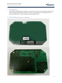
2. SRC-RCAN transceiver module

SRC-RCAN transceiver module
User & Installation Manual
4
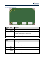
3. Terminal connection
Connector
(CAN)
Signal
Description
G
CAN
Ground
L
CAN LOW
CAN-bus signal CAN low
No function (Resting position for optional shield)
H
CAN HIGH
CAN-bus signal CAN high
No function (Resting position for optional CAN V+)
Connector
(Relays)
Signal
Description
C
Function
relay
common
Common signal for Function relays
F1
Function
relay 1
Function relay 1 output (Horn)
F2
Function
relay 2
Function relay 2 output (Light)
SC
STOP
Common
Common signal for STOP relays
S
STOP
STOP relays output (2 in series)

SRC-RCAN transceiver module
User & Installation Manual
5
Connector
(Mains)
Signal
Description
N
Neural
Power neural supply 48VAC – 230VAC (50/60Hz)
GND
Protective Earth
L
Line
Power line supply 48VAC – 230VAC (50/60Hz)
4. Radio specification
Attribute
Information
Frequency
2405-2480 MHz
Channels
16
Channels
management
FHSS
Channel BW
2.8 MHz
Channel separation
5 MHz
RF Power
0.098 W Max
Modulation
0-QPSK
Range
100 meters
5. Antenna specification
This radio transmitter, 6476A-SRCRCAN, has been approved by Innovation, Science and Economic
Development Canada to operate with the antenna types listed below, with the maximum permissible
gain indicated. Antenna types not included in this list that have a gain greater than the maximum
gain indicated for any type listed are strictly prohibited for use with this device.
N
Antenna
type
Details
Manufacturer
Part number
Connector
Gain,
dBi
1
Omni-
directional
Dipole(whip),
L=82mm, Ø17mm
Scanreco
50250
TNC
2 dBi
2
Omni-
directional
Monopole, F shape,
H=23mm, Ø 76 mm
Reel
M70XCR/
M71XCR
TNC
4 dBi
3
Omni-
directional
Monopole, F shape
22mmx7mm
Scanreco
50127
Soldered
2 dBi
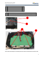
6. Installation

SRC-RCAN transceiver module
User & Installation Manual
6
Pos.
Article
Nr.
1
Host Bottom Section
1
2
Ventilation Membrane PTFE
1
3
SRC-RCAN module
1
4
Screw Torx 3,0x8mm Zinc Plated
6
N
Instruction
1
Place the membrane (Pos 2) in the Host bottom part (Pos 1) acc. to figure 1.
2
Mount the SRC-RCAN module (Pos 2) with 6 screws (Pos 4). Torque = 0.7 Nm.
Figure 1
Figure 2
Note: Cables should always be routed away from the module to avoid interference with the radio.
4
2
3
1

SRC-RCAN transceiver module
User & Installation Manual
7
7. Regulatory information
7.1 FCC Information
This equipment has been tested and found to comply with the limits for a Class A digital device,
pursuant to part 15 of the FCC Rules. These limits are designed to provide reasonable protection
against harmful interference when the equipment is operated in a commercial environment. This
equipment generates, uses, and can radiate radio frequency energy and, if not installed and used in
accordance with the instruction manual, may cause harmful interference to radio communications.
Operation of this equipment in a residential area is likely to cause harmful interference in which case
the user will be required to correct the interference at his own expense.
This device compiles with Part 15 of FCC Rules. Operation is subject to the following two conditions:
1. This device may not cause harmful interference, and
2. This device must accept any interference received, including interference that may cause
undesirable operation.
Warning
Changes or modifications not expressly approved by the party responsible for compliance could void
the user’s authority to operate the equipment.
7.2 Industry Canada Information
This device contains licence-exempt transmitter(s)/receiver(s) that comply with Innovation, Science
and Economic Development Canada’s licence-exempt RSS(s). Operation is subject to the following
two conditions:
(1) This device may not cause interference.
(2) This device must accept any interference, including interference that may cause undesired
operation of the device.
L’émetteur/récepteur exempt de licence contenu dans le présent appareil est conforme aux CNR
d’Innovation, Sciences et Développement économique Canada applicables aux appareils radio
exempts de licence. L’exploitation est autorisée aux deux conditions suivantes :
(1) L’appareil ne doit pas produire de brouillage;
(2) L’appareil doit accepter tout brouillage radioélectrique subi, même si le brouillage est susceptible
d’en compromettre le fonctionnement.
CAN ICES-3 (A)/NMB-3(A)
7.3 Radiation Exposure Statement
To comply with FCC/IC RF exposure limits for general population / uncontrolled exposure, the
antenna used for this transmitter must be installed to provide a separation distance of at least 20 cm
from all persons and must not be co-located or operating in conjunction with any other antenna or
transmitter.
Déclaration d’exposition à la radiation
Pour se conformer aux limites d'exposition RF FCC / IC pour la population générale / exposition
incontrôlée, la ou les antenne utilisées pour cet émetteur doivent être installées de manière à fournir

SRC-RCAN transceiver module
User & Installation Manual
8
une distance de séparation d'au moins 20 cm de toutes les personnes et ne doivent pas être
colocalisées ou en fonctionnement en conjonction avec toute autre antenne ou émetteur.
Revision history
Release
Date: YYYY-MM-DD
Edited By
Changes
A
2021-06-17
Fredrik Markström
Rev A
B
2021-11-16
Fredrik Markström
Rev B
-
 1
1
-
 2
2
-
 3
3
-
 4
4
-
 5
5
-
 6
6
-
 7
7
-
 8
8


dans d''autres langues
- English: Scanreco SRC-RCAN User manual
Autres documents
-
Beeper RW037-P User& Installer's Manual
-
-
-
Samsung SV-DVD1EA Mode d'emploi
-
TRIMBLE R780 Mode d'emploi
-
Intermec IM11 Integration Manual
-
Datalogic 0022 Mode d'emploi
-
Johnson Controls TE-7800 Series Installation Instructions Manual
-
Xylem M420 Transceiver Mode d'emploi