Johnson Controls TE-7800 Series Installation Instructions Manual
- Taper
- Installation Instructions Manual

Refer to the QuickLIT website for the most up-to-date version of this document.
TE-7800 Series Receivers for One-to-One Wireless Room Temperature
Sensing Systems Installation Instructions
1
Application
The TE-7800 Series Receivers for One-to-One
wireless room temperature sensing systems receive
wireless Radio Frequency (RF) temperature data from
WRS Series Wireless Room Temperature Sensors,
and provide single zone temperature control data to
specified digital controllers in building Heating,
Ventilating, and Air Conditioning (HVAC) systems.
In a typical application, one WRS Series Sensor
reports to one TE-7800 Series Receiver; however, up
to four WRS Series Sensors can associate to a single
TE-7800 Series Receiver. In multi-sensor applications,
the receiver either averages the sensors’ temperature
input or selects the highest or lowest sensed
temperature for control of the target zone.
The TE-7820-x Series Receivers communicate over
a zone bus interface with Johnson Controls®
VMA14 Series Controllers. The receiver supplies the
sensed zone temperature, temperature setpoint, field
strength measurements, and low battery conditions.
The TE-7830-x Series Receivers communicate over
an analog interface with Johnson Controls AS-AHU,
AS-UNT, AS-VAV, DX-9100, and FXxx Series Field
Controllers. The TE-7830-x Series Receivers
communicate 0 to 5 VDC analog signals for zone
temperature and setpoint, binary inputs for low battery
indication, and occupancy status to the supported field
controllers.
Note: TE-78x0-1 Series Receivers (CE Mark
compliant models) have a reduced transmission power
(10 dBm) and transmission range to comply with the
requirements of select countries.
Refer to the TE-7800 Series One-to-One Wireless
Room Temperature Sensing System Technical Bulletin
(LIT-12011097) for information on commissioning TE-
7800 Series Receivers and configuring One-to-One
wireless temperature sensing systems.
The TE-7800 Series Receivers use direct-sequence,
spread-spectrum RF technology and operate on the
2.4 GHz Industrial, Scientific, Medical (ISM) band. The
receiver meets the IEEE 802.15.4 standard for low
power, low duty cycle RF transmitting systems.
A TE-7800 Series Receiver operates as a transceiver
to create a bidirectional association with a WRS Series
Sensor that allows the temperature sensing system to
confirm and synchronize data transmissions between
the sensor and the receiver.
IMPORTANT: The TE-7800 Series Receiver is
intended to provide an input to equipment under
normal operating conditions. Where failure or
malfunction of the receiver could lead to personal
injury or property damage to the controlled
equipment or other property, additional precautions
must be designed into the control system.
Incorporate and maintain other devices, such as
supervisory or alarm systems or safety or limit
controls, intended to warn of or protect against
failure or malfunction of the receiver.
IMPORTANT: Le TE-7800 Series Receiver est
destiné à transmettre des données entrantes à un
équipement dans des conditions normales de
fonctionnement. Lorsqu'une défaillance ou un
dysfonctionnement du receiver risque de provoquer
des blessures ou d'endommager l'équipement
contrôlé ou un autre équipement, la conception du
système de contrôle doit intégrer des dispositifs de
protection supplémentaires. Veiller dans ce cas à
intégrer de façon permanente d'autres dispositifs,
tels que des systèmes de supervision ou d'alarme,
ou des dispositifs de sécurité ou de limitation, ayant
une fonction d'avertissement ou de protection en
cas de défaillance ou de dysfonctionnement du
receiver.
IMPORTANT: The TE-7800 Series Receivers are
not designed or intended for use in mission-critical
or life/safety applications.
TE-7800 Series Receivers for One-to-One Wireless Room
Temperature Sensing Systems
Installation Instructions
TE-7820-0, TE-7830-0,
TE-7820-1, TE-7830-1
Part No. 24-10139-8, Rev. G
Issued February 2016

TE-7800 Series Receivers for One-to-One Wireless Room Temperature Sensing Systems Installation Instructions
2
North American Emissions Compliance
United States
Canada
Installation
Follow these guidelines:
• Transport the TE-7800 Series Receivers in the
original container to minimize vibration and shock
damage to the receiver.
• Verify that all the parts shipped with the receiver.
• Do not drop the receiver or subject it to physical
shock.
Parts Included
• one TE-7800 Series Receiver
• one omnidirectional indoor antenna
• one control interface and power cable
• four No. 6 pan-head, sheet-metal screws
• one installation instructions sheet
Dimensions
Mounting
Location Considerations
Receivers Using the Omnidirectional Indoor
Antenna
Follow these guidelines when locating a TE-
7800 Series Receiver using the omnidirectional
antenna.
• Locate the receiver so that it is easily accessible
(typically just above the ceiling tiles) and within
close proximity to the field controller when using
the 6 ft (1.8 m) power and zone bus interface cable
included with the receiver.
Note: Additional communication cables of
various lengths are available to connect the
(TE-7820-x Series) zone bus only (no power
cable). See Table 1 for details.
• The TE-7820-x Series Receivers may be
located up to 300 ft (91 m) from the
VMA14 Series Controller.
•The TE-7830-x Series Receivers may be
located up to 100 ft (30 m) from the supported
field controller.
This equipment has been tested and found to
comply with the limits for a Class A digital device
pursuant to Part 15 of the FCC Rules. These limits
are designed to provide reasonable protection
against harmful interference when this equipment is
operated in a commercial environment. This
equipment generates, uses, and can radiate radio
frequency energy and, if not installed and used in
accordance with the instruction manual, may cause
harmful interference to radio communications.
Operation of this equipment in a residential area is
likely to cause harmful interference, in which case
the user will be required to correct the interference
at his/her own expense.
This Class (A) digital apparatus meets all the
requirements of the Canadian Interference-Causing
Equipment Regulations.
Cet appareil numérique de la Classe (A) respecte
toutes les exigences du Règlement sur le matériel
brouilleur du Canada.
IMPORTANT: Before installing the TE-7800 Series
Receivers in plenum applications, verify acceptance
of exposed plastic materials in plenum areas with
the local building authority. Building codes for
plenum requirements vary by location. Some local
building authorities accept compliance to UL 1995,
Heating and Cooling Equipment, while others use
different acceptance criteria.
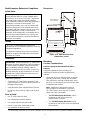
Figure 1: TE-7800 Series Receiver
Dimensions, in./mm
2-1/16
52
4-13/16
122
5-3/4
146
FIG:dmnsns
Omnidirectional
Indoor Antenna
5-1/2
140

TE-7800 Series Receivers for One-to-One Wireless Room Temperature Sensing Systems Installation Instructions
3
• Locate the receiver near the center of the
associated sensor layout in multi-sensor
applications.
• Locate the receiver on the same floor or building
level as the associated sensors. (Transmissions
may pass through floors. Test the transmission
strength before installing associated sensors and
receivers on different floors or building levels.)
• Locate the receiver in line-of-sight with the sensors
whenever possible.
• Mount the receiver in any orientation. For best
signal transmission, the antenna should be
oriented vertically, and at least 2 in. (50 mm) of the
tip of the antenna should be exposed below or
beyond any pipes, duct work, or other metal
obstructions in direct line-of-sight to the sensors.
• Avoid metal obstructions (including equipment
rooms and elevator shafts) and concrete/brick
walls between the receiver and sensors.
• Mount the receiver in metal enclosures, only if you
take special measures for the omnidirectional
antenna to protrude from the metal enclosure.
• Do not mount the receiver in recessed areas or
shelving units.
Wireless RF Signal Transmission Considerations
The maximum transmission range for indoor
line-of-sight transmissions between a WRS-TTx-0000-
0 Series Sensor and a TE-78x0-0 Series Receiver is
500 ft (152 m). Taking into consideration RF signal
absorption and reflection due to metal objects, walls,
and furniture found in typical building interiors, the
practical average indoor (line-of-sight) transmission
range between a sensor and receiver is 200 ft (61 m).
The maximum transmission range for indoor
line-of-sight transmissions between a WRS-TTx-0000-
1 Series Sensor and a TE-78x0-1 Series Receiver is
375 ft (114 m). Taking into consideration RF signal
absorption and reflection due to metal objects, walls,
and furniture found in typical building interiors, the
practical average indoor (line-of-sight) transmission
range between a sensor and receiver is 165 ft (50 m).
The RF signal strength between an installed sensor
and receiver can be tested by pressing and releasing
the occupancy button on the WRS Series Sensor.
Refer to the TE-7800 Series One-to-One Wireless
Room Temperature Sensing System Technical Bulletin
(LIT-12011097) for more information on determining
the signal strength between a WRS Series Sensor and
a TE-7800 Series Receiver.
You can also use the WRS-SST Series Wireless
Sensing System Tool to determine the RF signal
strength between the sensor and receiver locations.
Refer to the WRS-SST Series Wireless Sensing
System Tools Technical Bulletin
(Part No. 24-10139-16) for more information on testing
RF signal strength in your One-to-One application.
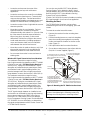
Mounting the Base
The TE-7800 Series Receivers can be surface
mounted using the four No. 6 self-tapping, pan-head
screws.
To mount the receiver base with screws:
1. Remove the receiver from the mounting base
(Figure 2).
2. Use the mounting base as a screw hole template;
place the mounting base against the mounting
surface and mark the location for the four screw
holes (Figure 2).
3. Drill a pilot hole at the four marked locations.
4. Secure the mounting base to the surface with the
(four) No. 6 screws supplied (Figure 2).
5. Reinstall receiver housing to the mounted base
(Figure 2).
IMPORTANT: Do not overtighten the mounting
screws. Overtightening the mounting screws may
damage the mounting base or mounting surface.
Figure 2: Mounting the TE-7800 Series Receivers
1. Remove the receiver housing
by pressing the locking tabs in at
the slots on the mounting base to
release the receiver from its base.
2. Use the mounting base
as a screw hole template.
3. Insert the four No. 6 screws into
the mounting holes on the mounting
base, and tighten them evenly to
the surface.
4. Reinstall the receiver
housing by aligning the
locking tabs with the slots
on the mounting base, and
pressing the housing until it
locks onto the base.
FIG:mntng
Slots
Locking
Tabs (4)

TE-7800 Series Receivers for One-to-One Wireless Room Temperature Sensing Systems Installation Instructions
4
Wiring
Wiring Considerations and Guidelines
Follow these guidelines when wiring a receiver:
• Route the power supply wires and Ethernet cables
at least 2 in. (50 mm) away from the vent slots on
the sides of the receiver housing.
• Provide slack in the wires and cables. Keep cables
routed neatly around the receiver to promote good
ventilation, Light-Emitting Diode (LED) visibility,
and ease of service.
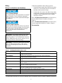
Wire a TE-7820-x Series Receiver up to 300 ft (91 m)
from the VMA14 Series Controller, as shown in
Figure 3.
Wire a TE-7830-x Series Receiver up to 100 ft (30 m)
from the supported controller, as shown in Figure 4.
Accessories
Risk of Property Damage.
Do not apply power to the system before checking all
wiring connections. Short circuited or improperly
connected wires may result in permanent damage to
the equipment.
Risque de dégâts matériels.
Ne pas mettre le système sous tension avant d'avoir
vérifié tous les raccords de câblage. Des fils formant
un court-circuit ou connectés de façon incorrecte
risquent d'endommager irrémédiablement
l'équipement.
IMPORTANT: Use copper conductors only. Make
all wiring in accordance with local, national, and
regional regulations. The TE-7800 Series Receivers
are low-voltage (less than 30 VAC) devices. Do not
exceed the receiver’s electrical ratings.
IMPORTANT: Prevent any static electric discharge
to the TE-7800 Series Receivers. Static electric
discharge can damage the receiver and void any
warranties.
Table 1: Ordering Information (Part 1 of 2)
Product Code Number Product Description
WRS-TTP0000-0
Wireless Room Temperature Sensor, Warmer/Cooler Setpoint Adjustment,
15 dBm Transmission Power
WRS-TTP0000-1 Wireless Room Temperature Sensor, Warmer/Cooler Setpoint Adjustment,
10 dBm Transmission Power (CE Mark)
WRS
-TTR0000-0
Wireless Room Temperature Sensor, No Setpoint Adjustment, 15 dBm Transmission
Power
WRS-TTR0000-1 Wireless Room Temperature Sensor, No Setpoint Adjustment, 10 dBm Transmission
Power (CE Mark)
WRS
-TTS0000-0
Wireless Room Temperature Sensor, Setpoint Adjustment Scale: 55 to 80°F and
12 to 28°C, 15 dBm Transmission Power
WRS-TTS0000-1 Wireless Room Temperature Sensor, Setpoint Adjustment Scale: 55 to 80°F and
12 to 28°C, 10 dBm Transmission Power (CE Mark)
WRS-SST-100 Wireless Sensing System Tool, 15 dBm Transmission Power
WRS-SST-101 Wireless Sensing System Tool, 10 dBm Transmission Power (CE Mark)
TP
-2420
Wall Plug Mount Transformer, 120 VAC to 24 VAC, 20 VA, Class 2

TE-7800 Series Receivers for One-to-One Wireless Room Temperature Sensing Systems Installation Instructions
5
Technical Specifications
Y65T31-0
1
Transformer, 102/208/240 VAC to 24 VAC, 40 VA, Class 2, Foot Mount, 8 in. (20 cm)
Primary Leads and Secondary Screw Terminals
CBL-STAT25 25 ft (7.6 m) Zone Bus Interface Cable to Connect TE-7820-x Series Receivers to
VMA14 Series Controllers; Does Not Include Power Cable
CBL-STAT50 50 ft (15.2 m) Zone Bus Interface Cable to Connect TE-7820-x Series Receivers to
VMA14 Series Controllers; Does Not Include Power Cable
CBL-STAT75 75 ft (22.9 m) Zone Bus Interface Cable to Connect TE-7820-x Series Receivers to
VMA14 Series Controllers; Does Not Include Power Cable
CBL-STAT100 100 ft (30.5 m) Zone Bus Interface Cable to Connect TE-7820-x Series Receivers to
VMA14 Series Controllers; Does Not Include Power Cable
1. Additional Y60 Series Transformers are available from Johnson Controls.
Table 1: Ordering Information (Part 2 of 2)
Product Code Number Product Description
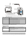
Figure 3: Wiring a TE-7820-x Series Receiver to a VMA14 Series Controller
AV G
HI G H
LOW
ZONE BUS
24 VAC
24 VAC COM
ZONE BUS
to VMA1400
(Tstat)
RF ADDRESS
MULT
XMTRS
TE-7820-0
RECEIVER
24 VAC COM
Power and Zone Bus Interface with
Johnson Controls VMA14 Series Digital Controller,
6 ft (1.8 m) Interface Cable included with TE-7820-x Series RF Receiver
To Supply
Transformer
T
s
t
a
t
2
4
V
A
C
:
2
24 VAC
2
4
V
A
C
:
1
TE-7820-x Series RF Receiver
with Zone Bus Interface
Johnson Controls
VMA14 Series
Digital Controller
RF SIGNAL
OFF ON
OFF ON
25 6
12 8
64
32
16
8
4
2
1
FIG:te7820_wrng
TE-7800 Series (Part 1 of 3)
Product Codes TE-7820-x Series Receivers for One-to-One Zone Bus Interface Applications
TE-7830-x Series Receivers for One-to-One 0 to 5 VDC Analog Interface Applications
Field Controller Interface TE-7820-x Series Receivers: Power and Zone Bus Interface between TE-7820-
x Series Receiver and VMA14 Series Controller
TE-7830-x Series Receivers: Power and 0 to 5 VDC Analog Interface between TE-
7830-x Series Receiver and AS-AHU, AS-UNT, AS-VAV, DX-9100, and FXxx Series
Controller
Power Requirements
24 VAC (+10%/
-15%), 50/60 Hz, 4.5 VA (Minimum) Class 2 Power Supply

TE-7800 Series Receivers for One-to-One Wireless Room Temperature Sensing Systems Installation Instructions
6
Addressing TE-7820-x Series Receivers: DIP Switches, Field Adjustable for up to 510 Unique
Addresses; for Addresses 0 and 511, the TE-7820-x Series Receiver Matches the
N2 Address of the Associated VMA14 Series Controller for Its Actual Address
TE-7830-x Series Receivers: DIP Switches, Field Adjustable for up to 510 Unique
Addresses; Addresses 0 and 511 are Invalid
Ambient Operating
Temperature Limits
32 to 122°F (0 to 50°C)
Ambient Operating Humidity
Limits
5 to 95% RH, Noncondensing
Ambient Storage Temperature
Limits
-40 to 160°F (-40 to 71°C)
Ambient Storage Humidity
Limits
5 to 90% RH, Noncondensing
RF Band Direct-Sequence, Spread-Spectrum, 2.4 GHz ISM Bands
Transmission Power TE-78x0-0 Series Receivers: 15 dBm Maximum
TE-78x0-1 Series Receivers: 10 dBm Maximum
Transmission Range
TE-78x0-0 Series Receivers: 500 ft (152 m) Maximum Indoor Line
-of-Sight;
200 ft (61 m) Practical Average Indoor
TE-78x0-1 Series Receivers: 375 ft (114 m) Maximum Indoor Line-of-Sight;
165 ft (50 m) Practical Average Indoor
Transmissions Every 60 Seconds (±20 Seconds)
TE-7800 Series (Part 2 of 3)
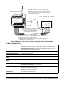
Figure 4: Wiring a TE-7830-x Series Receiver to an Analog Interface Field Controller
*
Relay Common (green wire) should be connected to either Binary In COM or
Binary In SRC, depending on the field controller.
24 VAC
Johnson Controls
AS-AHU, AS-UNT, AS-VAV, DX-9100, or
FXxx Series Controller
RF ADDRESS
TE-7830-0
RECEIVER
ANALOG INTERFACE
OUT COMMON
SET POINT OUT
ZONE TEMPERATURE OUT
RELAY COMMON
LOW BATTERY RELAY
OCCUPANCY RELAY
24 VAC COMMON
OFF ON
Tstat LOW BATTERY
REMOVE FOR AS-AHU, DX-9100
24 VAC COM
24 VAC COM
OCC BI
BI COM
*
TEMP AI-1
**
SET PT AI
AI COM
24 VAC
RED
BLK
BLU
YEL
GRN
WHT
ORN
BRN
RED
BLK
BLU
YEL
GRN
WHT
ORN
BRN
Note: Remove Jumper J1 for Johnson Controls AS-AHU,
DX-9100, and FXxx Series Controller applications that require
disabling the manual override status via the zone temperature.
Do not remove Jumper J1 for Johnson Controls AS-UNT or
AS-VAV Controller applications.
Jumper J1
RF SIGNAL
TE-7830-x Series RF Receiver
with Analog Interface
LOW BAT BI
To Supply
Transformer
Power and Analog Interface with
Johnson Controls AS-AHU, AS-UNT, AS-VAV,
DX-9100, or FXxx Series Controller,
6 ft (1.8 m) Interface Cable Included with
TE-7830-x Series RF Receiver
24 VAC
OFF ON
AVG
HIGH
LOW
OFF ON
256
128
64
32
16
8
4
2
1
**
Zone Temperature Out (white wire) should be connected to analog input AI-1
of the field controller (zone temperature).
FIG:te7830_wrng

Published in U.S.A. www.johnsoncontrols.com
TE-7800 Series Receivers for One-to-One Wireless Room Temperature Sensing Systems Installation Instructions
7
Metasys® and Johnson Controls® are registered trademarks of Johnson Controls, Inc.
All other marks herein are the marks of their respective owners. © 2016 Johnson Controls, Inc.
Building Efficiency
507 E. Michigan Street, Milwaukee, WI 53202
Receiver Outputs TE-7820-x Series Receivers: One Zone Bus Output for Temperature, Setpoint,
Field Strength Measurements, and Low Battery Indication
TE-7830-x Series Receivers: Two Analog Outputs for Zone Temperature and Setpoint:
0 to 5 VDC, 2 mA Maximum; Two Binary Outputs for Occupancy and Low Battery: Dry
Contacts Rated for 24 VAC, 50 mA Maximum
Temperature System Accuracy 1F° (0.6C°) Over the Range of 55 to 85°F (13 to 29°C);
1.5F° (0.9C°) Over a Range of 32 to 55°F (0 to 13°C) and 85 to 110°F (29 to 43°C)
Sensor Type Internal 10k ohm Negative Temperature Coefficient (NTC) Thermistor
Wiring Terminations and
Network Interfaces
TE-7820-x Series Receivers: One Two
-Position Terminal Block for 24 VAC Class 2
Supply Power and One Zone Bus Port
TE-7830-x Series Receivers: One Two
-Position Terminal Block for 24 VAC Class 2
Supply Power, One Three-Position Terminal Block for Occupancy and Low Battery
Binary Output Relays, and One Three-Position Terminal Block for Zone Temperature
and Setpoint Temperature Outputs
Materials
Gray Plastic Housing with UL94
-5VB Flammability Rating
Mounting
Screw Mount; Four No. 6 Pan
-Head, Sheet-Metal Screws Included
Compliance (TE-78x0-0 Series
Receivers)
United States: Intended for NEC Class 2 Connection
UL Listed, File E107041, CCN PAZX
UL 94
-5VB Flammability Rating
FCC Compliant to CFR 47, Part 15, Subpart B, Class A
Transmission Complies with FCC Part 15.247 Regulations for Low Power Unlicensed
Transmitters
Receiver Radio Module FCC Identification: CB2
-RFMOD2400A
Canada: Intended for CEC Class 2 Connection
UL Listed, File E107041, CCN PAZX7
UL 94
-5VB Flammability Rating
Industry Canada IC: 279A-RFMOD24A
Australia and New Zealand: RCM Mark, Australia/NZ Emissions Compliant
Compliance (TE-78x0-1 Series
Receivers)
Europe: CE Mark – Johnson Controls, Inc., declares that this product is in
compliance with the essential requirements and other relevant provisions of the
R&TTE Directive.
South Africa: Accepts Directives for Europe
Shipping Weight 1.0 lb (0.45 kg)
The performance specifications are nominal and conform to acceptable industry standards. For application at conditions beyond these
specifications, consult the local Johnson Controls office. Johnson Controls, Inc. shall not be liable for damages resulting from misapplication or
misuse of its products.
European Single Point of Contact: NA/SA Single Point of Contact: APAC Single Point of Contact:
JOHNSON CONTROLS
WESTENDHOF 3
45143 ESSEN
GERMANY
JOHNSON CONTROLS
507 E MICHIGAN ST
MILWAUKEE WI 53202
USA
JOHNSON CONTROLS
C/O CONTROLS PRODUCT
MANAGEMENT
NO. 22 BLOCK D NEW DISTRICT
WUXI JIANGSU PROVINCE 214142
CHINA
TE-7800 Series (Part 3 of 3)
-
 1
1
-
 2
2
-
 3
3
-
 4
4
-
 5
5
-
 6
6
-
 7
7


Johnson Controls TE-7800 Series Installation Instructions Manual
- Taper
- Installation Instructions Manual
dans d''autres langues
- English: Johnson Controls TE-7800 Series
Documents connexes
-
Johnson Controls NS-DTN7043-2 Guide d'installation
-
-
-
-
-
-
-
-
-
