La page est en cours de chargement...

WRS-RTN Series Receivers for Many-to-One Wireless Room
Temperature Sensing Systems Installation Instructions
1
Application
The WRS-RTN Series Receivers for the Many-to-One
Wireless Room Temperature Sensing Systems are
designed to receive wireless Radio Frequency (RF)
temperature data from multiple WRS-TTx Series
Wireless Room Temperature Sensors for multiple
temperature zones. Up to 60 WRS-TTx Series Sensors
can be associated with a single WRS-RTN Series
Receiver. The practical average due to typical
application environments is 10 to 20 sensors per
receiver.
Note: The WRS-RTN0000-1 Receiver (CE Mark
compliant model) has a reduced transmission power
(10 dBm) and transmission range to comply with the
requirements of select countries.
The WRS-RTN Series Receiver works in conjunction
with a Metasys® system Network Automation Engine
(NAE) or Network Control Engine (NCE) and provides
temperature data over Ethernet to the NAE or NCE.
The NAE or NCE processes the temperature data and
distributes the data to various field controllers on the
Metasys network.
The receiver uses direct-sequence, spread-spectrum
RF technology and operates on the 2.4 GHz ISM band.
The receiver meets the IEEE 802.15.4 standard for low
power, low duty cycle RF transmitting systems.
The WRS-RTN Series Receiver operates as a
transceiver to create a bidirectional association with
the sensors, which allows the temperature sensing
system to confirm and synchronize data transmissions
between the sensors and the receiver.
Refer to the WRS Series Many-to-One Wireless Room
Temperature Sensing System Technical Bulletin
(LIT-12011095) for information on commissioning and
configuring a WRS-RTN Series Receiver for operation
in a Many-to-One sensing system.
IMPORTANT: The WRS-RTN Series Receiver is
intended to provide an input to equipment under
normal operating conditions. Where failure or
malfunction of the receiver could lead to personal
injury or property damage to the controlled
equipment or other property, additional precautions
must be designed into the control system.
Incorporate and maintain other devices, such as
supervisory or alarm systems or safety or limit
controls, intended to warn of or protect against
failure or malfunction of the receiver.
IMPORTANT: Le WRS-RTN Series Receiver est
destiné à transmettre des données entrantes à un
équipement dans des conditions normales de
fonctionnement. Lorsqu'une défaillance ou un
dysfonctionnement du receiver risque de provoquer
des blessures ou d'endommager l'équipement
contrôlé ou un autre équipement, la conception du
système de contrôle doit intégrer des dispositifs de
protection supplémentaires. Veiller dans ce cas à
intégrer de façon permanente d'autres dispositifs,
tels que des systèmes de supervision ou d'alarme,
ou des dispositifs de sécurité ou de limitation, ayant
une fonction d'avertissement ou de protection en
cas de défaillance ou de dysfonctionnement du
receiver.
IMPORTANT: The WRS-RTN Series Receiver is
not designed or intended for use in mission-critical
or life/safety applications.
WRS-RTN Series Receivers for Many-to-One Wireless
Room Temperature Sensing Systems
Installation Instructions
WRS-RTN0000-0, WRS-RTN0000-1
Part No. 24-10126-0, Rev. G
Issued February 2016

WRS-RTN Series Receivers for Many-to-One Wireless Room Temperature Sensing Systems
Installation Instructions
2
North American Compliance Statement
United States
Canada
This equipment has been tested and found to
comply with the limits for a Class A digital device
pursuant to Part 15 of the FCC Rules. These limits
are designed to provide reasonable protection
against harmful interference when this equipment is
operated in a commercial environment. This
equipment generates, uses, and can radiate radio
frequency energy and, if not installed and used in
accordance with the instruction manual, may cause
harmful interference to radio communications.
Operation of this equipment in a residential area is
likely to cause harmful interference, in which case
the user will be required to correct the interference
at his/her own expense.
RF Transmitters: Compliance Statement
(Part 15.19)
This device complies with Part 15 of the FCC Rules.
Operation is subject to the following two conditions:
1. This device may not cause harmful interference,
and
2. This device must accept any interference
received, including interference that may cause
undesired operation.
Warning (Part 15.21)
Changes or modifications not expressly approved by
the party responsible for compliance could void the
user’s authority to operate the equipment.
RF Exposure (OET Bulletin 65)
To comply with FCC RF exposure requirements for
mobile transmitting devices, this transmitter should
only be used or installed at locations where there is
at least 20 cm separation distance between the
antenna and all persons.
This Class (A) digital apparatus meets all the
requirements of the Canadian Interference-Causing
Equipment Regulations.
Cet appareil numérique de la Classe (A) respecte
toutes les exigences du Règlement sur le matériel
brouilleur du Canada.
RF Transmitters: Industry Canada Statements
The term IC before the certification/registration
number only signifies that the Industry Canada
technical specifications were met.
This device has been designed to operate with an
antenna having a maximum gain of 2 dB. Antenna
having a higher gain is strictly prohibited per
regulations of Industry Canada. The required
antenna impedance is 50 ohms.
To reduce potential radio interference to other users,
the antenna type and its gain should be so chosen
that the Equivalent Isotropically Radiated Power
(EIRP) is not more than that required for successful
communication.
Le terme « IC » précédant le numéro d'accréditation/
inscription signifie simplement que le produit est
conforme aux spécifications techniques d'Industry
Canada.
Cet appareil a été conçu pour fonctionner avec une
antenne d'un gain maximum de 2 dBi. En application
des réglementations d'Industry Canada, l'utilisation
d'une antenne de gain supérieur est strictement
interdite. L'impédance d'antenne requise est de
50 ohms.
Pour réduire les interférences radio potentielles
avec les dispositifs d'autres utilisateurs, le type
d'antenne et son gain doivent être choisis de façon à
ce que la Puissance Isotrope Rayonnée Équivalente
(PIRE) ne soit pas supérieure à la puissance
nécessaire pour une bonne communication.

WRS-RTN Series Receivers for Many-to-One Wireless Room Temperature Sensing Systems
Installation Instructions
3
Installation
Follow these guidelines:
• Transport the WRS-RTN Series Receiver in the
original container to minimize vibration and shock
damage to the receiver.
• Verify that all the parts shipped with the receiver.
• Do not drop the receiver or subject it to physical
shock.
Parts Included
• one WRS-RTN Series Receiver
• one omnidirectional indoor antenna
• four No. 6 pan-head, sheet-metal screws
• one installation instructions sheet
Dimensions
Mounting
Location Considerations
Receivers Using the Omnidirectional Indoor
Antenna
Follow these guidelines when locating a
WRS-RTN Series Receiver using the omnidirectional
antenna.
• Locate the receiver so that it is easily accessible
(typically just above the ceiling tiles).
• Locate the receiver near the center of the sensor
array associated with the receiver.
• Locate the receiver on the same floor or building
level as the associated sensors. (Transmissions
may pass through floors. Test the transmission
strength before installing associated sensors and
receivers on different floors or building levels.)
• Locate the receiver in line-of-sight with as many
sensors as possible.
• Mount the receiver in any orientation; but for best
signal transmission, the antenna should be
oriented vertically with at least 2 in. (50 mm) of the
antenna tip exposed below and clear of any pipes,
duct work, or other metal obstructions, in direct
line-of-sight to the sensors.
• Avoid metal obstructions (including equipment
rooms and elevator shafts) and concrete or brick
walls between the receiver and sensors.
• Do not mount the receiver in recessed areas, metal
enclosures, or shelving units (unless the receiver
antenna is positioned as described in Installing the
Omnidirectional Indoor Antenna on page 5).
• Do not point the tip of the omnidirectional antenna
at any of the associated WRS-TTx Series Sensors.
Note: For detailed information on estimating the
number of WRS-RTN Series Receivers needed for a
Many-to-One application and locating the
WRS-RTN Series Receivers for optimum signal
coverage, refer to the WRS Series Many-to-One
Wireless Room Temperature Sensing System
Technical Bulletin (LIT-12011095).
IMPORTANT: Before installing the WRS-RTN
Series Receiver in plenum applications, verify
acceptance of exposed plastic materials in plenum
areas with the local building authority. Building
codes for plenum requirements vary by location.
Some local building authorities accept compliance to
UL 1995, Heating and Cooling Equipment, while
others use different acceptance criteria.
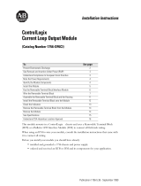
Figure 1: WRS-RTN Series Receiver,
Physical Features and Dimensions (in./mm)
24 VAC
Class 2
Power Supply
Port
Ethernet
Port
LED Receiver
Status Indicators
Omnidirectional
Antenna
5-3/4
146
4-31/32
126
2-1/16
52
5-1/2
140
Link
LED
Activity
LED
FIG:frnt_vw
Parameter
Reset
Button

WRS-RTN Series Receivers for Many-to-One Wireless Room Temperature Sensing Systems
Installation Instructions
4
Wireless RF Signal Transmission Considerations
The maximum transmission range for indoor
line-of-sight transmissions between a WRS-TTx Series
Sensor and a WRS-RTN0000-0 Receiver is
500 ft (152 m). Taking into consideration RF signal
absorption and reflection due to metal objects, walls,
and furniture found in typical building interiors, the
practical average indoor (line-of-sight) transmission
range between a sensor and receiver is 200 ft (61 m).
The maximum transmission range for indoor
line-of-sight transmissions between a WRS-TTx Series
Sensor and a WRS-RTN0000-1 Receiver is
375 ft (114 m). Taking into consideration RF signal
absorption and reflection due to metal objects, walls,
and furniture found in typical building interiors, the
practical average indoor (line-of-sight) transmission
range between a sensor and receiver is 165 ft (50 m).
The signal strength between an installed sensor and
receiver can be tested by pressing and releasing the
occupancy button on the WRS-TTx Series Sensor.
Refer to the WRS Series Many-to-One Wireless Room
Temperature Sensing System Technical Bulletin
(LIT-12011095) for more information on determining
the signal strength between a WRS-TTx Series Sensor
and a WRS-RTN Series Receiver.
Use a WRS-SST Series Wireless Sensing System Tool
to determine the radio frequency signal strength
between the sensor and receiver locations. Refer to the
WRS-SST Series Wireless Sensing System Tools
Technical Bulletin (Part No. 24-10139-16) for more
information on testing signal strength in your
application.
Mounting the Base
The WRS-RTN Series Receiver can be surface
mounted using the four No. 6 self-tapping, pan-head
screws supplied.
To mount the receiver base with screws:
1. Remove the receiver from the mounting base
(Figure 2).
2. Use the mounting base as a template; place the
mounting base against the mounting surface.
3. Drill pilot holes at the marked locations and secure
the mounting base to the surface with the (four)
No. 6 screws supplied.
4. Reinstall the receiver housing to the mounting
base.
IMPORTANT: Do not overtighten the mounting
screws. Overtightening the mounting screws may
damage the mounting base or mounting surface.
Figure 2: Mounting the WRS-RTN Series Receiver
1. Remove receiver housing by
pressing the locking tabs in at
the slots in the mounting base to
release the receiver from base.
2. Use the mounting base
for screw hole template.
3. Insert the four No. 6 screws into
mount holes on mounting base and
tighten them evenly to the surface.
4. Reinstall receiver
housing by aligning locking
tabs with slots on mounting
base and pressing housing
until it locks on to base.
FIG:mntng_rcvr
Slots
Locking
Tabs (4)

WRS-RTN Series Receivers for Many-to-One Wireless Room Temperature Sensing Systems
Installation Instructions
5
Wiring
Wiring Considerations and Guidelines
Follow these guidelines when wiring a receiver:
• Route the power supply wires and Ethernet cables
at least 2 in. (50 mm) away from the vent slots on
the sides of the receiver housing.
• Provide slack in the wires and cables. Keep cables
routed neatly around the receiver to promote good
ventilation, Light-Emitting Diode (LED) visibility,
and ease of service.
Connecting the Power Supply
The WRS-RTN Series Receiver requires a nominal
24 VAC, 50/60 Hz, 4.5 VA (minimum), Class 2 power
supply. The required minimum voltage is 20.4 VAC.
See Table 1 for recommended Johnson Controls®
transformers.
1. Connect the 24 VAC supply power wires from the
transformer to the removable three-terminal plug
as shown in Figure 3. The middle terminal is not
used.
Note: Transformers not manufactured by
Johnson Controls may have different color wires.
Follow the manufacturer’s instructions when mounting
and wiring transformers.
Connecting to the Ethernet Network
The (10 or 100 Mbps) Ethernet connection is an
eight-pin RJ-45 network port (Figure 1). Use the
Ethernet port to connect to the Internet Protocol (IP)
network on which the associated NAE or NCE resides.
Setup and Adjustments
Installing the Omnidirectional Indoor Antenna
The omnidirectional indoor antenna, supplied with the
receiver, fits the reverse polarity male Sub-Miniature
version A (SMA) connector.
To install the omnidirectional antenna:
1. Screw the omnidirectional antenna onto the
antenna port on the WRS-RTN Series Receiver.
2. Position the antenna in a vertical position with at
least 2 in. (50 mm) of the antenna tip exposed and
unobstructed by any pipes, duct work, or other
metal obstructions and in direct line-of-sight to the
sensors.
Risk of Property Damage.
Do not apply power to the system before checking all
wiring connections. Short circuited or improperly
connected wires may result in permanent damage to
the equipment.
Risque de dégâts matériels.
Ne pas mettre le système sous tension avant d'avoir
vérifié tous les raccords de câblage. Des fils formant
un court-circuit ou connectés de façon incorrecte
risquent d'endommager irrémédiablement
l'équipement.
IMPORTANT: Use copper conductors only. Make
all wiring in accordance with local, national, and
regional regulations. The WRS-RTN Series
Receiver is a low-voltage (less than 30 VAC) device.
Do not exceed the receiver’s electrical ratings.
IMPORTANT: Prevent any static electric discharge
to the WRS-RTN Series Receiver. Static electric
discharge can damage the receiver and void any
warranties.
IMPORTANT: You must assign an Internet
Protocol (IP) address to the WRS-RTN Series
Receiver before connecting the receiver to the
network the first time. Refer to the WRS Series
Many-to-One Wireless Room Temperature Sensing
System Technical Bulletin (LIT-12011095) for more
information on assigning an IP address to the
receiver.
Figure 3: WRS-RTN Power Supply Connection
Power
Terminal Block
Power Terminal
Block Plug
Wires from
Johnson Controls
24 VAC Class 2
Power Transformer
Brown Wire
(COM)
Orange Wire
(24 VAC)
FIG:pwr_prt
24V~
COM
HOT

WRS-RTN Series Receivers for Many-to-One Wireless Room Temperature Sensing Systems
Installation Instructions
6
Refer to the WRS Series Many-to-One Wireless Room
Temperature Sensing System Technical Bulletin
(LIT-12011095) and the WRS-SST Series Wireless
Sensing System Tools Technical Bulletin
(Part No. 24-10139-16) for more information.
Repair Information
If the WRS-RTN Series Receiver fails to operate within
its specifications, replace the unit. For a replacement
receiver, contact the nearest Johnson Controls
representative.
Accessories
Technical Specifications
Table 1: Accessories Ordering Information
Product Code Number Product Description
WRS-TTP0000-0
Wireless Room Temperature Sensor, Warmer/Cooler Setpoint Adjustment,
15 dBm Transmission Power
WRS
-TTP0000-1
Wireless Room Temperature Sensor, Warmer/Cooler Setpoint Adjustment,
10 dBm Transmission Power (CE Mark)
WRS-TTR0000-0
Wireless Room Temperature Sensor, No Setpoint Adjustment, 15 dBm Transmission
Power
WRS
-TTR0000-1
Wireless Room Temperature Sensor, No Setpoint Adjustment, 10 dBm Transmission
Power (CE Mark)
WRS
-TTS0000-0
Wireless Room Temperature Sensor, Setpoint Adjustment Scale: 55 to 85°F/13 to 29°C,
15 dBm Transmission Power
WRS-TTS0000-1
Wireless Room Temperature Sensor, Setpoint Adjustment Scale: 55 to 85°F/13 to 29°C,
10 dBm Transmission Power (CE Mark)
WRS-SST-100
Wireless Sensing System Tool (Monitors RF Signal Strength and Temperature Data
between a WRS-TTx0000-0 Series Sensor and the Associated WRS
-RTN0000-0 Series
or TE
-7800 Series Receiver), 15 dBm Transmission Power
WRS-SST
-101
Wireless Sensing System Tool (Monitors RF Signal Strength and Temperature Data
between a WRS-TTx0000-1 Series Sensor and the Associated WRS
-RTN0000-1 Series
or TE-7800 Series Receiver), 10 dBm Transmission Power (CE Mark)
TP-2420
Transformer, Wall Plug Mount, 120 VAC to 24 VAC, 20 VA, Class 2
Y65T31-0
1
1. Additional Y60 Series Transformers are available from Johnson Controls.
Transformer, 102/208/240 VAC to 24 VAC, 40 VA, Class 2, Foot Mount, 8 in. (20 cm)
Primary Leads and Secondary Screw Terminals
WRS-RTN Series Receivers for Many-to-One Wireless Room Temperature Sensing
Systems (Part 1 of 2)
Power Requirements
24 VAC (+10%/
-15%), 50/60 Hz, 4.5 VA (Minimum) Class 2 Power Supply
Addressing Configurable via the NAE or NCE for up to 511 Unique Transmitter ID Addresses and up
to 31 Property Code Addresses.
Ambient Operating
Temperature Limits
32 to 122°F (0 to 50°C )
Ambient Operating
Humidity Limits
5 to 95% RH, Noncondensing
Ambient Storage
Temperature Limits
-40 to 160°F (-40 to 71°C)
Ambient Storage
Humidity Limits
5 to 90% RH, Noncondensing
RF Band Direct-Sequence, Spread-Spectrum, 2.4 GHz ISM Bands
Transmission Power WRS-RTN0000-0 Receiver: 15 dBm Maximum
WRS-RTN0000-1 Receiver: 10 dBm Maximum

Published in U.S.A. www.johnsoncontrols.com
WRS-RTN Series Receivers for Many-to-One Wireless Room Temperature Sensing Systems
Installation Instructions
7
Metasys® and Johnson Controls® are registered trademarks of Johnson Controls, Inc.
All other marks herein are the marks of their respective owners. © 2016 Johnson Controls, Inc.
Building Efficiency
507 E. Michigan Street, Milwaukee, WI 53202
The performance specifications are nominal and conform to acceptable industry standard. For application at conditions beyond these
specifications, consult the local Johnson Controls office. Johnson Controls, Inc. shall not be liable for damages resulting from misapplication or
misuse of its products.
Transmission Range
WRS-RTN0000-0 Receiver: 500 ft (152 m) Maximum Indoor Line
-of-Sight;
200 ft (61 m) Practical Average Indoor
WRS-RTN0000-1 Receiver: 375 ft (114 m) Maximum Indoor Line
-of-Sight;
165 ft (50 m) Practical Average Indoor
Receiver Outputs One Ethernet Connection for Communicating Temperature, Setpoint, Occupancy Status,
Field Strength Measurements, and Low Battery Conditions
Temperature System Accuracy 1F° (0.6C°) Over the Range of 55 to 85°F (13 to 29°C);
1.5F° (0.9C°) Over a Range of 32 to 55°F (0 to 13°C) and 85 to 110°F (29 to 43°C)
Wiring Terminations and
Network Interfaces
One Three
-Position Terminal Block with Removable Terminal Plug for 24 VAC Supply
Power; One 10/100 Mbps, Eight-Pin, RJ-45 Ethernet Port
Network Bandwidth
Requirement
Less than 0.02% on a 10 Mbps Ethernet Connection
Materials
Gray Plastic Housing with UL94-5VB Flammability Rating
Mounting
Screw Mount; Four No. 6 Pan
-Head, Sheet-Metal Screws Included
Compliance (WRS-RTN0000-0
Receiver)
United States: Intended for NEC Class 2 Connection
UL Listed, File E107041, CCN PAZX
UL 94
-5VB Flammability Rating
FCC Compliant to CFR 47, Part 15, Subpart B, Class A
Transmission Complies with FCC Part 15.247 Regulations for Low Power Unlicensed
Transmitters
Transmitter FCC Identification: CB2
-TMPSENS2400A
Canada: Intended for CEC Class 2 Connection
UL Listed, File E107041, CCN PAZX7
UL 94
-5VB Flammability Rating
Industry Canada IC: 279A-TSENS24A
Australia and New Zealand: RCM Mark, Australia/NZ Emissions Compliant
Compliance (WRS-RTN0000-1
Receiver)
Europe: CE Mark – Johnson Controls, Inc., declares that this product is in
compliance with the essential requirements and other relevant provisions of the
R&TTE Directive.
South Africa: Accepts Directives for Europe
Shipping Weight 1.0 lb (0.45 kg)
European Single Point of Contact: NA/SA Single Point of Contact: APAC Single Point of Contact:
JOHNSON CONTROLS
WESTENDHOF 3
45143 ESSEN
GERMANY
JOHNSON CONTROLS
507 E MICHIGAN ST
MILWAUKEE WI 53202
USA
JOHNSON CONTROLS
C/O CONTROLS PRODUCT
MANAGEMENT
NO. 22 BLOCK D NEW DISTRICT
WUXI JIANGSU PROVINCE 214142
CHINA
WRS-RTN Series Receivers for Many-to-One Wireless Room Temperature Sensing
Systems (Part 2 of 2)
1/7