
Publication 1756-5.36 - September 1999
Installation Instructions
ControlLogix
Current Loop Output Module
(Catalog Number 1756-OF6CI)
7KLVPRGXOHPRXQWVLQD&RQWURO/RJL[FKDVVLVDQGXVHVD5HPRYDEOH7HUPLQDO%ORFN
57%RUD%XOOHWLQ,QWHUIDFH0RGXOH,)0WRFRQQHFWDOOILHOGVLGHZLULQJ
:KHQXVLQJDQ,)0WRZLUH\RXUPRGXOHFRQVXOWWKHLQVWDOODWLRQLQVWUXFWLRQVWKDWFDPHZLWK
LWWRFRQQHFWDOOZLULQJ
%HIRUH\RXLQVWDOO\RXUPRGXOH\RXVKRXOGKDYHDOUHDG\
• LQVWDOOHGDQGJURXQGHGDFKDVVLVDQGSRZHUVXSSO\
• RUGHUHGDQGUHFHLYHGDQ57%RU,)0DQGLWVFRPSRQHQWVIRU\RXUDSSOLFDWLRQ
To: See page:
Prevent Electrostatic Discharge 2
See Removal and Insertion Under Power (RIUP) 2
Understand Compliance to European Union Directive 3
Note the Power Requirements 4
Identify the Module Components 4
Install the Module 5
Key the Removable Terminal Block/Interface Module 6
Wire the Removable Terminal Block 7
Assemble the Removable Terminal Block and the Housing 11
Install the Removable Terminal Block onto the Module 12
Check the Indicators 13
Remove the Removable Terminal Block from the Module 14
Remove the Module 14
See Specifications 15
Understand CSA Hazardous Location Approval 16
Allen-Bradley Drives

2 ControlLogix Current Loop Output Module
Publication 1756-5.36 - September 1999
Prevent Electrostatic Discharge
Removal and Insertion Under Power (RIUP)
ATTENTION
!
(OHFWURVWDWLF GLVFKDUJHFDQGDPDJHLQWHJUDWHGFLUFXLWVRU
VHPLFRQGXFWRUVLI\RXWRXFKEDFNSODQH FRQQHFWRUSLQV)ROORZ
WKHVHJXLGHOLQHVZKHQ\RXKDQGOHWKHPRGXOH
• 7RXFKDJURXQGHGREMHFWWRGLVFKDUJH
VWDWLFSRWHQWLDO
• :HDUDQDSSURYHGZULVWVWUDSJURXQGLQJGHYLFH
• 'RQRWWRXFKWKHEDFNSODQHFRQQHFWRURU
FRQQHFWRUSLQV
• 'RQRWWRXFKFLUFXLWFRPSRQHQWVLQVLGHWKHPRGXOH
• ,IDYDLODEOHXVHDVWDWLFVDIHZRUNVWDWLRQ
• :KHQQRWLQXVHNHH SWKHPRGXOHLQLWVVWDWLFVKLHOGER[
ATTENTION
!
7KLVPRGXOHLVGHVLJQHGVR\RXFDQUHPRYHDQGLQVHUWLWXQGHU
EDFNSODQHSRZHUDQGILHOGVLGHSRZHU:KHQ\RXUHPRYHRULQVHUWD
PRGXOHZKLOHILHOGVLGHSRZHULVDSSOLHG\RXPD\FDXVHDQHOHFWULFDO
DUF$QHOHFWULFDODUFFDQFDXVHSHUVRQDOLQMXU\RUSURSHUW\GDPDJH
EHFDXVHLWPD\
• VHQGDQHUURQHRXVVLJQDOWR\RXUV\VWHP·VILHOGGHYLFHVFDXVLQJ
XQLQWHQGHGPDFKLQHPRWLRQRUORVVRISURFHVVFRQWURO
• FDXVHDQH[SORVLRQLQDKD]DUGRXVHQYLURQPHQW
5HSHDWHGHOHFWULFDODUFLQJFDXVHVH[FHVVLYHZHDUWRFRQWDFWVRQERWK
WKHPRGXOHDQGLWVPDWLQJFRQQHFWRU:RUQFRQ WDFWVPD\FUHDWH
HOHFWULFDOUHVLVWDQFH

ControlLogix Current Loop Output Module 3
Publication 1756-5.36 - September 1999
Understand Compliance to European Union Directive
,IWKLVSURGXFWEHDUVWKH&(PDUNLQJLWLVDSSURYHGIRULQVWDOODWLRQZLWKLQWKH(XURSHDQ
8QLRQDQG(($UHJLRQV,WKDVEHHQGHVLJQHGDQGWHVWHGWRPHHWWKHIROORZLQJGLUHFWLYHV
EMC Directive
7KLV SURGXFWLVWHVWHGWRPHHW&RXQFLO'LUHFWLYH((&(OHFWURPDJQHWLF
&RPSDWLELOLW\(0&DQGWKHIROORZLQJVWDQGDUGV LQZKROHRULQSD U WGRFXPHQWHGLQD
WHFKQLFDOFRQVWUXFWLR QILOH
• (1(0&*HQHULF(PLVVLRQ6WDQGDUG3DUW,QGXVWULDO(QYLURQPHQW
• (1(0&*HQHULF,PPXQLW\6WDQGDUG3DU W,QGXVWULDO(QYLURQPHQW
7KLVSURGXFWLVLQWHQGHGIRUXVHLQDQLQGXVWULDOHQYLURQPHQW
Low Voltage Directive
7KLV SURGXFWLVWHVWHGWRPHHW&RXQFLO'LUHFWLYH((&/RZ9R OWDJHE\DSSO\LQJWKH
VDIHW\UHTXLUHPHQWVRI(1 3URJUDPPDEOH&RQWUROOHUV3DU W(TXLSPHQW
5HTXLUHPHQWVDQG7H VWV
)RUVSHFLILFLQIRUPDWLRQUHTXLUHGE\(1VHHWKHDSSURSULDWHVHFWLRQ VLQWKLV
SXEOLFDWLRQ DVZHOODVWKHIROORZLQJ$OOHQ%UDGOH\SXEOL FDWLRQV
• ,QGXVWULDO$XWRPDWLRQ:LULQJDQG*URXQGLQJ*XLGHOLQHV)RU1RLVH,PPXQLW\
SXEOLFDWLRQ
• $XWRPDWLRQ6\VWHPV&DWDORJSXEOLFDWLRQ%
7KLVHTXLSPHQWLVFODVVLILHGDVRSHQHTXLSPHQWDQGPXVWEHLQVWDOOHGPRXQWHGLQDQ
HQFORVXUHGXULQJRSHUDWLRQDVDPHDQVRISURYLGLQJVDIHW\SURWHFWLRQ
Allen-Bradley Drives

4 ControlLogix Current Loop Output Module
Publication 1756-5.36 - September 1999
Note the Power Requirements
7KLVPRGXO HUHFHLYHVSRZHUIURPWKHFKDVLVSRZHUVXSSO\DQGUHTXLUHVVRXUFHVRI
SRZHUIURPWKHEDFNSODQH
• P$DW9GFDQGP$DW9GFIRUORDGVRIΩ
• P$DW9GFDQGP$DW9GFIRUORDGVRIΩ
$GGWKLVFXUUHQWWRWKHUHTXLUHPHQWVRIDOORWKHUPRGXOHVLQWKHFKDVVLVWRSUHYHQW
RYHUORDGLQJWKHFKDVVLVEDFNSODQH
Identify the Module Components
<RXUHFHLYHGWKHIROORZLQJFRPSRQHQWVZLWK\RXURUGHU
,I\RXGLGQRWUHFHLYHWKHVHFRPSRQHQWVFRQWDFW\RXUORFDO5RFNZHOO$XWRPDWLRQVDOHVRIILFH
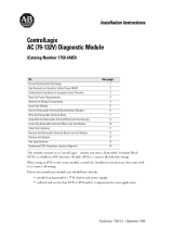
Removable Terminal Block and Housing
$VHSDUD WHO\ RUGHUHG57%FRQQHFWVILHOGVLGHZLULQJWRWKHPRGXOH<RXFDQQRWXVH\RXU
PRGXOHZLWKRXWDQ57%DQGLWVFRPSRQHQWV
8VHRQHRIWKHIROORZLQJ57%VZLWK\RXUPRGXOH
• 7%1+SRVLWLRQ1(0$57%
• 7%6+SRVLWLRQ6SULQJ&ODPS57%
20966-M
Side view Front view
1756-OF6CI module RTB door label

ControlLogix Current Loop Output Module 5
Publication 1756-5.36 - September 1999
<RXUHFHLYHGWKHIROORZLQJFRPSRQHQWVZLWK\RXU57%
• VWDQGDUGGHSWK57%KRXVLQJ
• ZHGJHVKD SHGNH\LQJWDEVDQG8VKDSHGNH\LQJEDQGV
• DJHQHULF57%GRRUODEHO
8VHWKHVHFRPSRQHQWVLQDOOPRGXOHDSSOLFDWLRQV8VHDQRSWLRQDOH[WHQGHGGHSWKFRYHU
7%(IRUDSSOLFDWLRQVUHTXLULQJDGGLWLRQDOURXWLQJVSDFH
Install the Module
<RXFDQLQVWDOORUUHPRYHWKHPRGXOHZKLOHFKDVVLVSRZHULVDSSOLHG
ATTENTION
!
7KHPRGXO HLVGHVLJQHGWRVXSSRUW5HPRYDODQG,QVHUWLRQ 8QGHU
3RZHU5,83+RZHYHUZKHQ\RXUHPRYHRULQVHUWDQ57%ZLWK
ILHOGVLGHSRZHUDSSOLHGXQLQWHQGHGPDFKLQHPRWLRQRUORVVRI
SURFHVVFRQWUROFDQRFFXU([HUFLVHH[WUHPHFDXWLRQZKHQXVLQJ
WKLVIHDWXUH
20861–M 20862–M
21
Align circuit board with top and
bottom chassis guides.
Slide module into chassis
until module tabs ‘click’.
Printed
Circuit
Board
Locking tab
Allen-Bradley Drives

6 ControlLogix Current Loop Output Module
Publication 1756-5.36 - September 1999
Key the Removable Terminal Block/Interface Module
.H\WKH57%RU,)0WRSUHYHQWLQDGYHUWDQWO\PDNLQJWKHZURQJZLUHFRQQHFWLRQVWR\RXU
PRGXOH8VHDXQLTXHNH\LQJSDWWHUQIRUHDFKPRGXOH<RXFDQXVHDPLQLPXPRIRQHNH\
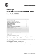
.H\WKHPRGXOH,QVHUWWKH8VKDSHGEDQGZLWKWKHORQJHUVLGHQHDUWKHWHUPLQDO V
3XVKWKHEDQGRQWRWKHPRGXOHXQWLOLWVQDSVLQWRSODFH
.H\WKH57%LQSRVLWLRQVWKDWFRUUHVSRQGWRXQNH\HGPRGXOHSRVLWLRQV,QVHUWWKH
ZHGJHVKD SHGWDERQWKH57%ZLWKWKHURXQGHGHGJHILUVW3XVKWKHWDERQWRWKH
57%XQWLOLWVWRSV
5HSRVLWLRQWKHWDEV WRUHNH\IXWXUHPRGXOHDSSOLFDWLRQV
20850–M
U-shaped
Keying Band
20851–M
1
2
0
3
4
5
6
7
Wedge-shaped
Keying Tab
Begin keying in
section #6 or #7.
Module side of RTB

ControlLogix Current Loop Output Module 7
Publication 1756-5.36 - September 1999
Wire the Removable Terminal Block
:LUHWKH57%EHIRUHLQVWDOOLQJLWRQWRWKHPRGXOH8VHDLQFKPPPD[LP XP
IODWEODGHGVFUHZGUL YHU
,0325 7$173XOOWKHKRXVLQJRIIRIWKH57%EHIRUHZLULQJ
6KLHOGHGFDEOHLVUHTXLUHGZKHQXVLQJWKLVPRGXOH:HUHFRPPHQGXVLQJ%HOGHQFDEOH
WRZLUHWKH5 7%7KH5 7%WHUPLQDWLRQVFDQDFFRPPRGDWHJDXJHVKLHOGHGZLUH
Connect grounded end of the cable
*URXQGWKHGUDLQZLUH
,03257$17:HUHFRPPHQGJURXQGLQJWKHGUDLQZLUHDWWKHILHOGVLGH,I\RXFDQQRW
JURXQGDWWKHILHOGVLGH JURXQGDWDQHDUWKJ URXQGRQWKHFKDVVLVDVVKRZQEHORZ
&RQQHFWWKHLQVXODWHGZLUHVWRWKHILHOGVL GH
Connect ungrounded end of the cable
&XWWKHIRLOVKLHOGDQGGUDLQZLUHEDFNWRWKHFDEOHFDVLQJDQGDSSO\VKULQNZUDS
&RQQHFWWKHLQVXODWHGZLUHVWRWKH57%VHHSDJH
20104-M
20918-M
a. Remove a length
of cable jacket
from the
connecting cable.
b. Pull the foil shield
and bare drain
wire from the
insulated wire.
c. Twist the foil shield
and drain wire
together to form a
single strand.
d. Attach a ground lug
and apply heat
shrink tubing to the
exit area.
e. Connect the drain wire to a
chassis mounting tab.
Use any chassis mounting
tab that is designated as a
functional signal ground.
Chassis mounting tab
Drain wire with ground lug
4M or 5M (#10 or #12)
phillips screw and star
washer (or SEM screw)
4M or 5M (#10 or #12)
star washer
Allen-Bradley Drives

8 ControlLogix Current Loop Output Module
Publication 1756-5.36 - September 1999
For the Spring Clamp RTB
6WULSLQFK PPPD[LPXPOHQJWKWRZLUH\RXU57%
,QVHUWWKHVFUHZG ULYHULQWRWKHLQQHUKROHRIWKH57%
,QVHUWWKHZLUHLQWRWKHRSHQWHUPLQDODQGUHPRYHWKHVFUHZGUL YHU
For the NEMA Screw RTB
6WULSLQFKPPPD[LPXPOHQJWKWRZLUH\RXU57%
:LUHWKHWHUPLQDOV
20863–M

ControlLogix Current Loop Output Module 9
Publication 1756-5.36 - September 1999
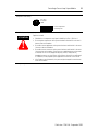
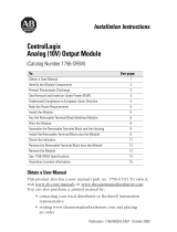
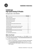
Wiring example
20967-M
12
34
56
78
910
1112
1314
1516
1718
1920
i
NOTE: Place additional devices anywhere in the loop.
OUT-1
ALT-1
RTN-1
OUT-3
RTN-3
Not used
OUT-5
ALT-5
ALT-3
RTN-5
OUT-0
ALT-0
RTN-0
OUT-2
RTN-2
Not used
OUT-4
ALT-4
ALT-2
RTN-4
User Analog
Output Device
Shield Ground
1756-OF6CI wiring example for loads of 0-550
Ω
Allen-Bradley Drives

10 ControlLogix Current Loop Output Module
Publication 1756-5.36 - September 1999
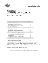
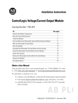
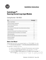
$IWHUILHOGVLGHZLULQJLVFRPSOHWHVHFXUHWKHZLUHVLQWKHVWUDLQUHOLHIDUHDZLWKDFDEOHWLH
40854-M
12
34
56
78
910
1112
1314
1516
1718
1920
i
NOTE: Place additional devices anywhere in the loop.
OUT-1
ALT-1
RTN-1
OUT-3
RTN-3
Not used
OUT-5
ALT-5
ALT-3
RTN-5
OUT-0
ALT-0
RTN-0
OUT-2
RTN-2
Not used
OUT-4
ALT-4
ALT-2
RTN-4
User Analog
Output Device
Shield Ground
1756-OF6CI wiring example for loads of 551-1000
Ω

ControlLogix Current Loop Output Module 11
Publication 1756-5.36 - September 1999
Assemble the Removable Terminal Block and the Housing
$OLJQWKHJURRYHVDWWKHERWWRPRIHDFKVLGHRIWKHKRXVLQJZLWKWKHVLGHHGJHV
RIWKH57%
6OLGHWKH57%LQWRWKHKRXVLQJXQWLOLWVQDSVLQWRSODFH
20852-M
Groove
Groove
Side edge of the RTB
Side edge of the RTB
Strain relief area
1756-TBNH RTB shown for reference
Allen-Bradley Drives

12 ControlLogix Current Loop Output Module
Publication 1756-5.36 - September 1999
Install the Removable Terminal Block onto the Module
%HIRUHLQVWDOOLQJWKH57%PDNHFHUWDLQ
• ILHOGVLGHZLULQJRIWKH57%KDVEHHQFRPSOHWHG
• WKH57%KRXVLQJLVVQDSSHGLQWRSODF HRQWKH57%
• WKH57%KRXVLQJGRRULVFORVHG
• WKHORFNLQJWDEDWWKHWRSRIWKHPRGXOHLVXQORFNHG
ATTENTION
!
6KRFNKD]DUGH[LVWV,IWKH57%LVLQVWDOOHGRQWRWKHPRGXOHZKLOH
WKHILHOGVLGHSRZHULVDSSOLHGWKH57%ZLOOEHHOHFWULFDOO\OLYH'R
QRWWRXFKWKH57%·VWHUPLQDOV)DLOXUHWRREVHUYHWKLVFDXWLRQPD\
FDXVHSHUVRQDOLQMXU\
7KH57%LV GHVLJQHGWRVXSSRUW5HPRYDODQG,QVHUWLRQ8QGHU
3RZHU5,83+RZHYHUZKHQ\RXUHPRYHRULQVHUWDQ57%ZLWK
ILHOGVLGHSRZHUDSSOLHGXQLQWHQGHGPDFKLQHPRWLRQRUORVVRI
SURFHVVFRQWUROFDQRFFXU([HUFLVHH[WUHPHFDXWLRQZKHQXVLQJ
WKLVIHDWXUH,WLVUHFRPPHQGHGWKDWILHOGVLGHSRZHUEHUHPRYHG
EHIRUHLQVWDOOLQJWKH57%RQWRWKHPRGXOH
20853–M
20854–M
Top
guide
Left-side guides
Bottom guide
Locking
tab
Align the top, bottom and left
side guides of the RTB with
the guides on the module.
Press quickly and evenly to seat
the RTB on the module until the
latches snap into place. Slide
the locking tab down to lock the
RTB onto the module.

ControlLogix Current Loop Output Module 13
Publication 1756-5.36 - September 1999
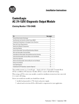
Check the Indicators
7KHLQGLFDWRUVVKRZ&$/VWDWXVJUHHQDQGDELFRORUHG/('IRUPRGXOH2.UHGJUHHQ
'XULQJSRZHUXSDQLQGLFDWRUWHVWLVGRQH7KH2.LQGLFDWRUWXUQVUHGIRUVHFRQGDQG
WKHQWXUQVWRIODVKLQJJUHHQLILWKDVSDV VHGWKHVHOIWHVW
7KLVFRPSOHWHVLQVWDOODWLRQRIWKHPRGXOH8VHWKHIROORZLQJLQIRUPDWLRQWRUHPRYHWKH57%
DQGPRGXOH
LED
indicators:
This display: Means: Take this action:
OK Steady green light The outputs are in a normal
operating state.
None
OK Flashing green light The module has passed
internal diagnostics but is not
actively controlled.
None
OK Flashing red light Previously established
communication has timed
out.
Check controller and chassis
communication
OK Steady red light The module must be
replaced.
Replace the module.
CAL Flashing green light The module is in calibration
mode.
None
20965-M
ANALOG OUTPUT
CAL
OK
Allen-Bradley Drives

14 ControlLogix Current Loop Output Module
Publication 1756-5.36 - September 1999
Remove the Removable Terminal Block from the Module
%HIRUHUHPRYLQJWKHPRGXOH\RXP XVWUHPRY HWKH57%
8QORFNWKHORFNLQJWDEDWWKHWRSRIWKHPRGXOH
2SHQWKH5 7%GRRUDQGSXOOWKH57%RIIWKHPRGXOHDVVKRZQEHORZ
Remove the Module
ATTENTION
!
6KRFNKD]DUGH[LVWV,IWKH57%LVUHPRYHGIURPWKHPRGXOH
ZKLOHWKHILHOGVLGHSRZHULVDSSOLHGWKHPRGXOHZLOOEHHOHFWULFDOO\
OLYH'RQRWWRXFKWKH57%·VWHUPLQDOV)DLOXUHWRREVHUYHWKLV
FDXWLRQPD\FDXVHSHUVRQDOLQMXU\
7KH57%LV GHVLJQHGWRVXSSRUW5HPRYDODQG,QVHUWLRQ8QGHU
3RZHU5,83+RZHYHUZKHQ\RXUHPRYHRULQVHUWDQ57%ZLWK
ILHOGVLGHSRZHUDSSOLHGXQLQWHQGHGPDFKLQHPRW LRQRUORVVRI
SURFHVVFRQWUROFDQRFFXU([HUFLVHH[WUHPHFDXWLRQZKHQXVLQJ
WKLVIHDWXUH,WLVUHFRPPHQGHGWKDWILHOGVLGHSRZHUEHUHPRYHG
EHIRUHUHPRYLQJWKHPRGXOH
20855–M
20856–M 20857–M
3XVKLQWRSDQGERWWRPORFNLQJWDEV 3XOOPRGXOHRXWRIWKHFKDVVLV

ControlLogix Current Loop Output Module 15
Publication 1756-5.36 - September 1999
1756-OF6CI Specifications
Number of Outputs 6 individually isolated channels
Module Location 1756 ControlLogix Chassis
Backplane Power Requirements
(No external power requirements)
250mA @ 5.1V dc & 225mA @ 24V dc (0-550
Ω
loads terminated
on OUTs and RTNs) (6.7W)
250mA @ 5.1V dc & 300mA @ 24V dc (551-1000
Ω
loads
terminated on OUTs and ALTs) (8.5W)
Power Dissipation within Module
Thermal Dissipation
5.5W (0-550
Ω
loads)
6.1W (551-1000
Ω
loads)
18.76 BTU/hr (0-550
Ω
loads)
20.80 BTU/hr (551-1000
Ω
loads)
Output Current Range 0 to 21mA
Current Resolution 13 bits across 21mA (2.7µA)
Data Format Integer mode (Left justified, 2s complement)
Floating point IEEE 32 bit
Open Circuit Detection None
Output Overvoltage Protection 24V ac/dc maximum
Output Short Circuit Protection Electronically current limited to 21mA or less
Drive Capability 0-1000
Ω
Separate field terminations for ranges 0-550
Ω
or 551-1000
Ω
Output Settling Time <2ms to 95% of final value with resistive loads
Calibrated Accuracy at 25°C
Calibration Interval
Better than 0.1% of range from 4mA to 21mA
Six months typical
Output Offset Drift with Temperature 1 µA/degree C typical
Gain Drift with Temperature 60 ppm/degree C typical (100 ppm maximum)
Module Error over Full Temp. Range 0.6% of range
Module Scan Time for all Channels 25ms maximum floating point
10ms maximum integer
Isolation Voltage
Channel to channel
User to system
Optoisolated, tranformer isolated
100% tested at 1700V dc for 1s, based on 250V ac
100% tested at 1700V dc for 1s, based on 250V ac
Module Conversion Method R-Ladder DAC, monotonicity with no missing codes
Inductive Load <1 mH
RTB Screw Torque (NEMA) 7-9 inch-pounds (0.8-1Nm)
Module Keying (Backplane) Electronic
RTB Keying User defined
Field Wiring Arm and Housing
20 Position RTB (1756-TBNH or TBSH)
1
Environmental Conditions
Operating Temperature
Storage Temperature
Relative Humidity
0 to 60°C (32 to 140°F)
-40 to 85°C (-40 to 185°F)
5 to 95% noncondensing
Conductors Wire Size
Category
22-14 gauge (2mm
2
) stranded maximum
1
3/64 inch (1.2mm) insulation maximum
2
2, 3
Screwdriver Width for RTB 5/16 inch (8mm) maximum
Allen-Bradley Drives

16 ControlLogix Current Loop Output Module
Publication 1756-5.36 - September 1999
CSA Hazardous Location Approval
User Manual Publication 1756-6.5.9
Agency Certification
(when product or packaging is marked)
1
Maximum wire size will require extended housing - 1756-TBE.
2
Use this conductor category information for planning conductor routing as described in
the system level installation manual.
3
Refer to publication 1770-4.1, "Programmable Controller Wiring and Grounding Guidelines”
4
CSA certification–Class I, Division 2, Group A, B, C, D or nonhazardous locations.
FM approved–Class I, Division 2, Group A, B, C, D or nonhazardous locations.
5
Shielded cable required.
CSA certifies products for general use as well as for use in hazardous locations. Actual CSA certification is
indicated by the product label as shown below, and not by statements in any user documentation.
Example of the CSA certification product label:
To comply with CSA certification for use in hazardous locations, the following information becomes a part of
the product literature for this CSA-certified industrial constrol product::
•
This equipment is suitable for use in Class I, Division 2, Groups A, B, C, D, or non-hazardous locations only.
•
The products having the appropriate CSA markings (that is, Class I, Division 2, Groups A, B, C, D) are
certified for use in other equipment where the suitability of combination (that is, application or use) is
determined by the CSA or the local inspection office having jurisdiction.
IMPORTANT
Due to the modular nature of a programmable control system, the product with the
highest temperature rating determines the overall temperature code rating of a
programmable control system in a Class I, Division 2 location. The temperature code
rating is marked on the product label as shown.
marked for all applicable directives
5
Class I Div 2 Hazardous
4
Class I Div 2 Hazardous
4
marked for all applicable acts
N223
CL I, DIV 2
GP A,B,C,D
TEMP

ControlLogix Current Loop Output Module 17
Publication 1756-5.36 - September 1999
Temperature code rating:
The following warnings apply to products having CSA certification for use in hazardous locations.
ATTENTION
!
Explosion hazard!
•
Substitution of components may impair suitability for Class I, Division 2.
•
Do not replace components unless power has been switched off or the area is
known to be non-hazardous.
•
Do not disconnect equipment unless power has been switched off or the area
is known to be non-hazardous.
•
Do not disconnect connectors unless power has been switched off or the area
is known to be non-hazardous. Secure any user-supplied connectors that mate
to external circuits on this equipment by using screws, sliding latches,
threaded connectors, or other means such that any connection can withstand
a 15 Newton (3.4 lb) separating force applied for a minimum of one minute.
•
If the Product contains batteries, they must only be changed in an area known
to be non-hazardous.
CSA logo is a registered trademark of the Canadian Standards Association.
CL I, DIV 2
GP A,B,C,D
TEMP
Look for temperature
code rating here.
Allen-Bradley Drives

18 ControlLogix Current Loop Output Module
Publication 1756-5.36 - September 1999
Approbation d’utilisation dans des environnements dangereux par la CSA
La CSA certifie des produits pour une utilisation générale aussi bien que pour une utilisation en
environnements dangereux. La certification CSA en vigueur est indiquée par l'étiquette produit et non par des
indications dans la documentation utilisateur.
Exemple d'étiquette de certification d'un produit par la CSA:
Pour satisfaire à la certification CSA en environnements dangereux, les informations suivantes font partie
intégrante de la documentation des produits de commande industrielle certifiés.
•
Cet équipement ne convient qu’à une utilisation en environnements de Classe 1, Division 2,
Groupes A, B, C, D ou non dangereux.
•
Les produits portant le marquage CSA approprié (c'est-à-dire Classe 1, Division 2, Groupes A, B, C, D) sont
certifiés pour une utilisation avec d'autres équipements, les combinaisons d’applications et d’utilisations
étant déterminées par la CSA ou le bureau local d'inspection qualifié.
IMPORTANT
De par la nature modulaire des systèmes de commande programmables, le produit ayant
le code de température le plus élevé détermine le code de température global du
système dans un environnement de Classe 1, Division 2. Le code de température est
indiqué sur l'étiquette produit.
CL I, DIV 2
GP A,B,C,D
TEMP
CL I, DIV 2
GP A,B,C,D
TEMP
Le code de température
est indiqué ici.

ControlLogix Current Loop Output Module 19
Publication 1756-5.36 - September 1999
Les avertissements suivants s’appliquent aux produits ayant la certification CSA pour une utilisation en
environnements dangereux.
ATTENTION
!
Risque d’explosion
•
La substitution de composants peut rendre cet équipement inadapté à une
utilisation en environnements de Classe 1, Division 2.
•
Couper le courant ou s'assurer que l’environnement est classé non dangereux
avant de remplacer des composants.
•
Couper le courant ou s’assurer que l’environnement est classé non dangereux
avant de débrancher l'équipement.
•
Couper le courant ou s'assurer que l’environnement est classé non dangereux
avant de débrancher les connecteurs. Fixer tous les connecteurs fournis par
l'utilisateur pour se brancher aux circuits externes de cet équipement à l 'aide
de vis, loquets coulissants, connecteurs filetés ou autres, de sorte que les
connexions résistent à une force de séparation de 15 Newtons
(1,5 kg - 3,4 lb.) appliquée pendant au moins une minute.
•
S'assurer que l'environnement est classé non dangereux avant de changer
les piles.
Le sigle CSA est une marque déposée de l’Association des Standards pour le Canada.
Allen-Bradley Drives

Publication 1756-5.36 - September 1999 PN 957236-15
Supersedes Publication 1756-5.36 - February 1998 © 1999 Rockwell International Corporation. Printed in the U.S.A.
-
 1
1
-
 2
2
-
 3
3
-
 4
4
-
 5
5
-
 6
6
-
 7
7
-
 8
8
-
 9
9
-
 10
10
-
 11
11
-
 12
12
-
 13
13
-
 14
14
-
 15
15
-
 16
16
-
 17
17
-
 18
18
-
 19
19
-
 20
20


Allen-Bradley ControlLogix 1756-OF6VI Installation Instructions Manual
- Taper
- Installation Instructions Manual
- Ce manuel convient également à
dans d''autres langues
Documents connexes
-
 Allen-Bradley ControlLogix 1756-IA16I Installation Instructions Manual
-
 Allen-Bradley ControlLogix 1756-OA8D Installation Instructions Manual
-
 Allen-Bradley ControlLogix 1756-IB16D Installation Instructions Manual
-
Allen-Bradley ControlLogix 1756-IH16I Installation Instructions Manual
-
 Allen-Bradley ControlLogix 1756-OX8I Installation Instructions Manual
-
 Allen-Bradley ControlLogix 1756-OF6VI Installation Instructions Manual
-
 Allen-Bradley ControlLogix 1756-OF4 Installation Instructions Manual
-
 Allen-Bradley ControlLogix 1756-IF4FXOF2F Installation Instructions Manual
-
 Allen-Bradley ControlLogix 1756-IF6CIS Installation Instructions Manual


