
Publication 1756-5.5 - September 1999
Installation Instructions
ControlLogix
AC (79-132V) Diagnostic Module
(Catalog Number 1756-IA8D)
•
•
To: See page:
Prevent Electrostatic Discharge 2
See Removal and Insertion Under Power (RIUP) 2
Understand Compliance to European Union Directive 3
Note the Power Requirements 4
Identify the Module Components 4
Install the Module 5
Key the Removable Terminal Block/Interface Module 6
Wire the Removable Terminal Block 7
Assemble the Removable Terminal Block and the Housing 9
Install the Removable Terminal Block onto the Module 10
Check the Indicators 11
Remove the Removable Terminal Block from the Module 12
Remove the Module 12
See Specifications 13
Understand CSA Hazardous Location Approval 14
Allen-Bradley Drives

2 ControlLogix AC (79-132V) Diagnostic Module
Publication 1756-5.5 - September 1999
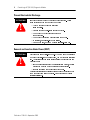
Prevent Electrostatic Discharge
Removal and Insertion Under Power (RIUP)
ATTENTION
!
•
•
•
•
•
•
ATTENTION
!
•
•

ControlLogix AC (79-132V) Diagnostic Module 3
Publication 1756-5.5 - September 1999
Understand Compliance to European Union Directive
EMC Directive
•
•
Low Voltage Directive
•
•
Allen-Bradley Drives

4 ControlLogix AC (79-132V) Diagnostic Module
Publication 1756-5.5 - September 1999
Note the Power Requirements
•
•
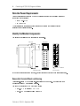
Identify the Module Components
Removable Terminal Block and Housing
•
•
20928-M
Side view Front view
1756-IA8D module RTB door label

ControlLogix AC (79-132V) Diagnostic Module 5
Publication 1756-5.5 - September 1999
•
•
•
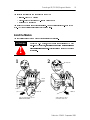
Install the Module
ATTENTION
!
20861–M 20862–M
21
Align circuit board with top and
bottom chassis guides.
Slide module into chassis
until module tabs ‘click’.
Printed
Circuit
Board
Locking tab
Allen-Bradley Drives

6 ControlLogix AC (79-132V) Diagnostic Module
Publication 1756-5.5 - September 1999
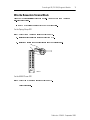
Key the Removable Terminal Block/Interface Module
20850–M
U-shaped
Keying Band
20851–M
1
2
0
3
4
5
6
7
Wedge-shaped
Keying Tab
Begin keying in
section #6 or #7.
Module side of RTB

ControlLogix AC (79-132V) Diagnostic Module 7
Publication 1756-5.5 - September 1999
Wire the Removable Terminal Block
For the Spring Clamp RTB
For the NEMA Screw RTB
20863–M
Allen-Bradley Drives

8 ControlLogix AC (79-132V) Diagnostic Module
Publication 1756-5.5 - September 1999
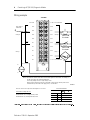
Wiring example
12
34
5
6
7
8
910
1112
1314
1516
1718
19
20
47k
Ω,
1/2W,
5% resistor
47k
Ω,
1/2W,
5% resistor
NOTES: All terminals with the same name are connected together on the module. For example, L2
can be connected to any terminal marked L2-0.
This wiring example shows a single voltage source.
When you daisy chain from a group to other RTBs, alway connect the daisy chain to the
terminal directly connected to the supply wire, as shown above.
40202-M
Resistors are not necessary if Wire Off diagnostic is not used.
To Determine Leakage Resistor
(P/S = Field side power supply)
R
LEAK
Maximum = (P/S Voltage-19V ac)/1.5mA
R
LEAK
Minimum = (P/S Voltage-20V ac)/2.5mA
Not used
L2-0
L2-0
L2-0
L2-0
L2-1
L2-1
L2-1
L2-1
L2-1
L1-0 Loss of Field Power
IN-0
IN-1
IN-2
IN-3
IN-4
IN-5
IN-6
IN-7
L1-1 Loss of Field Power
Daisy chain to
other RTBs
Group 0Group 0
Group 1Group 1
L2
L1
Recommended Values
43k
Ω
47k
Ω
47k
Ω
51k
Ω
1756-IA8D

ControlLogix AC (79-132V) Diagnostic Module 9
Publication 1756-5.5 - September 1999
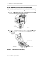
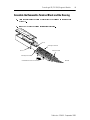
Assemble the Removable Terminal Block and the Housing
20852-M
Groove
Groove
Side edge of the RTB
Side edge of the RTB
Strain relief area
1756-TBNH RTB shown for reference
Allen-Bradley Drives

10 ControlLogix AC (79-132V) Diagnostic Module
Publication 1756-5.5 - September 1999
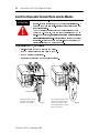
Install the Removable Terminal Block onto the Module
•
•
•
•
ATTENTION
!
20853–M
20854–M
Top
guide
Left-side guides
Bottom guide
Locking
tab
Align the top, bottom and left
side guides of the RTB with
the guides on the module.
Press quickly and evenly to seat
the RTB on the module until the
latches snap into place. Slide
the locking tab down to lock the
RTB onto the module.

ControlLogix AC (79-132V) Diagnostic Module 11
Publication 1756-5.5 - September 1999
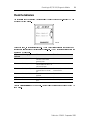
Check the Indicators
LED
indicator:
This display: Means: Take this action:
OK Steady green light The inputs are being
multicast and in normal
operating state.
None
OK Flashing green light The module has passed
internal diagnostics but is not
multicasting inputs.
None
OK Flashing red light Previously established
communication has timed
out.
Check controller and chassis
communication.
OK Steady red light The module must be
replaced.
Replace the module.
I/O State Yellow The input is active. None
I/O Fault Red A fault has occurred for this
point.
Check this point at the controller.
20927-M
Allen-Bradley Drives

12 ControlLogix AC (79-132V) Diagnostic Module
Publication 1756-5.5 - September 1999
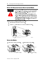
Remove the Removable Terminal Block from the Module
Remove the Module
ATTENTION
!
20855–M
20856–M 20857–M

ControlLogix AC (79-132V) Diagnostic Module 13
Publication 1756-5.5 - September 1999
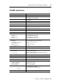
1756-IA8D Specifications
Number of Inputs 8 (4 points/common)
Module Location 1756 ControlLogix Chassis
Backplane Current 100mA @ 5.1V dc & 3mA @ 24V dc
(Total backplane power 0.58W)
Maximum Power Dissipation (Module)
4.5W @ 60
o
C
Thermal Dissipation 15.35 BTU/hr
On-State Voltage Range 79-132V ac, 47-63Hz
Nominal Input Voltage 120V ac
On-State Current 74V @ 5mA ac, 47-63Hz minimum
16mA @ 132V ac, 47-63Hz maximum
Maximum Off-State Voltage 20V
Maximum Off-State Current 2.5mA
Maximum Input Impedance @ 132V ac 8.25k
Ω
@ 60Hz
Input Delay Time
Off to on
Hardware Delay
On to Off
Hardware Delay
Programmable filter: 1ms & 2ms
10ms maximum plus filter time
Programmable filter: 9ms & 18ms
8ms maximum plus filter time
Diagnostic Functions
Open Wire
Loss of Power
Time Stamp of Diagnostics
Change of State
Time stamp of Inputs
Off state leakage current 1.5mA minimum
Transition range 46 to 85V ac
+/- 1ms
Software configurable
+/- 200µs
Short/Inrush Current 250mA peak (decaying to <37% in 22ms, without activation)
Cyclic Update Time User Selectable (200µs minimum/750ms maximum)
Isolation Voltage
Group to group
User to system
100% tested at 2546V dc for 1s
(250V ac maximum continuous voltage between groups)
100% tested at 2546V dc for 1s
RTB Screw Torque (NEMA) 7-9 inch-pounds (0.8-1Nm)
Module Keying (Backplane) Software configurable
RTB Keying User defined mechanical keying
Field Wiring Arm and Housing
20 Position RTB (1756-TBNH or TBSH)
1
Environmental Conditions
Operating Temperature
Storage Temperature
Relative Humidity
0 to 60°C (32 to 140°F)
-40 to 85°C (-40 to 185°F)
5 to 95% noncondensing
Conductors Wire Size
Category
22-14 gauge (2mm
2
) stranded
1
3/64 inch (1.2mm) insulation maximum
1
2, 3
Screwdriver Width for RTB 5/16 inch (8mm) maximum
Allen-Bradley Drives

14 ControlLogix AC (79-132V) Diagnostic Module
Publication 1756-5.5 - September 1999
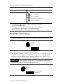
CSA Hazardous Location Approval
User Manual Publication 1756-6.5.8
Agency Certification
(when product or packaging is marked)
1
Maximum wire size will require extended housing - 1756-TBE.
2
Use this conductor category information for planning conductor routing as described in
the system level installation manual.
3
Refer to publication 1770-4.1, "Programmable Controller Wiring and Grounding Guidelines”
4
CSA certification–Class I, Division 2, Group A, B, C, D or nonhazardous locations.
FM approved–Class I, Division 2, Group A, B, C, D or nonhazardous locations.
CSA certifies products for general use as well as for use in hazardous locations. Actual CSA certification is
indicated by the product label as shown below, and not by statements in any user documentation.
Example of the CSA certification product label:
To comply with CSA certification for use in hazardous locations, the following information becomes a part of
the product literature for this CSA-certified industrial constrol product::
•
This equipment is suitable for use in Class I, Division 2, Groups A, B, C, D, or non-hazardous locations only.
•
The products having the appropriate CSA markings (that is, Class I, Division 2, Groups A, B, C, D) are
certified for use in other equipment where the suitability of combination (that is, application or use) is
determined by the CSA or the local inspection office having jurisdiction.
IMPORTANT
Due to the modular nature of a programmable control system, the product with the
highest temperature rating determines the overall temperature code rating of a
programmable control system in a Class I, Division 2 location. The temperature code
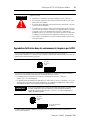
rating is marked on the product label as shown.
Temperature code rating:
The following warnings apply to products having CSA certification for use in hazardous locations.
marked for all applicable directives
Class I Div 2 Hazardous
4
Class I Div 2 Hazardous
4
marked for all applicable acts
N223
CL I, DIV 2
GP A,B,C,D
TEMP
CL I, DIV 2
GP A,B,C,D
TEMP
Look for temperature
code rating here.

ControlLogix AC (79-132V) Diagnostic Module 15
Publication 1756-5.5 - September 1999
Approbation d’utilisation dans des environnements dangereux par la CSA
ATTENTION
!
Explosion hazard!
•
Substitution of components may impair suitability for Class I, Division 2.
•
Do not replace components unless power has been switched off or the area is
known to be non-hazardous.
•
Do not disconnect equipment unless power has been switched off or the area
is known to be non-hazardous.
•
Do not disconnect connectors unless power has been switched off or the area
is known to be non-hazardous. Secure any user-supplied connectors that mate
to external circuits on this equipment by using screws, sliding latches,
threaded connectors, or other means such that any connection can withstand
a 15 Newton (3.4 lb) separating force applied for a minimum of one minute.
•
If the Product contains batteries, they must only be changed in an area known
to be non-hazardous.
CSA logo is a registered trademark of the Canadian Standards Association.
La CSA certifie des produits pour une utilisation générale aussi bien que pour une utilisation en
environnements dangereux. La certification CSA en vigueur est indiquée par l'étiquette produit et non par des
indications dans la documentation utilisateur.
Exemple d'étiquette de certification d'un produit par la CSA:
Pour satisfaire à la certification CSA en environnements dangereux, les informations suivantes font partie
intégrante de la documentation des produits de commande industrielle certifiés.
•
Cet équipement ne convient qu’à une utilisation en environnements de Classe 1, Division 2,
Groupes A, B, C, D ou non dangereux.
•
Les produits portant le marquage CSA approprié (c'est-à-dire Classe 1, Division 2, Groupes A, B, C, D) sont
certifiés pour une utilisation avec d'autres équipements, les combinaisons d’applications et d’utilisations
étant déterminées par la CSA ou le bureau local d'inspection qualifié.
IMPORTANT
De par la nature modulaire des systèmes de commande programmables, le produit ayant
le code de température le plus élevé détermine le code de température global du
système dans un environnement de Classe 1, Division 2. Le code de température est
indiqué sur l'étiquette produit.
Les avertissements suivants s'appliquent aux produits ayant la certification CSA pour une utilisation en
environnements dangereux.
CL I, DIV 2
GP A,B,C,D
TEMP
CL I, DIV 2
GP A,B,C,D
TEMP
Le code de température
est indiqué ici.
Allen-Bradley Drives

Publication 1756-5.5 - September 1999 PN 957236-37
Supersedes Publication 1756-5.5 - October 1998 © 1999 Rockwell International Corporation. Printed in the U.S.A.
ATTENTION
!
Risque d’explosion
•
La substitution de composants peut rendre cet équipement inadapté à une
utilisation en environnements de Classe 1, Division 2.
•
Couper le courant ou s'assurer que l’environnement est classé non dangereux
avant de remplacer des composants.
•
Couper le courant ou s’assurer que l’environnement est classé non dangereux
avant de débrancher l'équipement.
•
Couper le courant ou s'assurer que l’environnement est classé non dangereux
avant de débrancher les connecteurs. Fixer tous les connecteurs fournis par
l'utilisateur pour se brancher aux circuits externes de cet équipement à l 'aide
de vis, loquets coulissants, connecteurs filetés ou autres, de sorte que les
connexions résistent à une force de séparation de 15 Newtons
(1,5 kg - 3,4 lb.) appliquée pendant au moins une minute.
•
S'assurer que l'environnement est classé non dangereux avant de changer
les piles.
Le sigle CSA est une marque déposée de l’Association des Standards pour le Canada.
-
 1
1
-
 2
2
-
 3
3
-
 4
4
-
 5
5
-
 6
6
-
 7
7
-
 8
8
-
 9
9
-
 10
10
-
 11
11
-
 12
12
-
 13
13
-
 14
14
-
 15
15
-
 16
16


Allen-Bradley ControlLogix 1756-IB16D Installation Instructions Manual
- Taper
- Installation Instructions Manual
- Ce manuel convient également à
dans d''autres langues
Documents connexes
-
 Allen-Bradley ControlLogix 1756-OA8D Installation Instructions Manual
-
 Allen-Bradley ControlLogix 1756-IA16I Installation Instructions Manual
-
 Allen-Bradley ControlLogix 1756-OX8I Installation Instructions Manual
-
Allen-Bradley ControlLogix 1756-IH16I Installation Instructions Manual
-
 Allen-Bradley ControlLogix 1756-OF6VI Installation Instructions Manual


