
INFORMAZIONI TECNICHE
TECHNICAL INFORMATION
INFORMATIONS TECHNIQUES
TECHNISCHE INFORMATIONEN
INFORMACIONES TECNICAS
ART. 14364E
FULL SYSTEM 1/1
LV ONE EVO
KTM 690 ENDURO R
KTM 690 SMC R
(Also fits 35kW version)
TYPE: KTM 690 LC4; A/-, B/-
16-10-21 REV.01

NOTE / NOTES / REMARQUES /
ANMERKUNGEN / NOTAS
Cognome//Surname/Nom/ Name/ Apellido
Targa veicolo/Vehicle registration plate/Plaque d’immatriculation/Kennzeichen des Fahrzeuges/Matrícula del vehículo
Data e timbro del rivenditore
Date and seller’s stamp
Date et tampon du revendeur
Datum und Stempel des Verkäufers
Fecha y sello del vendedor
Tel.
Indirizzo /Address/Adresse/Adresse/ Dirección
Nome/Given name/Prénom/Vorname/ Nombre
ART. 14364E

3
INDICE - INDEX - INHALTSVERZEICHNIS - INDICE
Lista dei componenti/List of components
Liste des composants/Inhaltsverzeichnis
Lista de componentes pag. 4
PESO/wEIgHT/POIdS/gEwICHT pag. 5
Disegno tecnico/Technical drawing/Eclaté
Technische Zeichnung/Despiece pag. 6
Istruzioni di montaggio pag. 8
Fitting instructions pag. 10
Notice de montage pag. 12
Montageanleitungen pag. 14
Instrucciones de montaje pag. 16
Foto/Photo/Photo/bilder/Foto pag. 18
PHOTO 9
PHOTO 10
22

4
LISTA DEI COMPONENTI - LIST OF COMPONENTS - LISTE DES
COMPOSANTS - VERPACKUNGSINHALT - LISTA DE COMPONENTES
ITALIANO
1 - Silenziatore
2 - Collettore
3 - Collettore
4 - Kit minuteria
5 - Carter paracalore
ENGLISH
1 - Muffler
2 - Link pipe
3 - Link pipe
4 - Fitting kit
5 - Heat shield
FRANCAIS
1 - Silencieux
2 - Tube de raccord
3 - Tube de raccord
4 - Kit de fixation
5 - Cache pare-chaleur
DEUTSCH
1 - Endschalldämpf
2 - Verbindungsrohr
3 - Verbindungsrohr
4 - Haltesatz
5 - Hitzeschild
ESPAÑOL
1 - Silenciador
2 - Tubo de conexión
3 - Tubo de conexión
4 - Kit de montaje
5- Protector de calor
ACCIAIO INOX
cod. 3014363482
cod. 3014364201
cod. 3014364203
cod. 3014364601
cod. 088213001
STAINLESS S.
cod. 3014363482
cod. 3014364201
cod. 3014364203
cod. 3014364601
cod. 088213001
ACIER INOX
cod. 3014363482
cod. 3014364201
cod. 3014364203
cod. 3014364601
cod. 088213001
EDELSTHAL
cod. 3014363482
cod. 3014364201
cod. 3014364203
cod. 3014364601
cod. 088213001
ACERO INOX
cod. 3014363482
cod. 3014364201
cod. 3014364203
cod. 3014364601
cod. 088213001
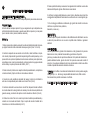
PHOTO 7
PHOTO 8
21

5
PESO - WEIGHT - POIDS - GEWICHT (Kg)
ORIGINALE - STOCK - ORIGINE - ORIGINAL 6,016 (Kg)
Stainless steel Carbon Titanium
LeoVince 5,21 / /
20
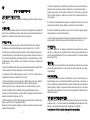
PHOTO 5
PHOTO 6

6
125
110
31
Db-Killer N.65
Cod.
3014324801
160
e.75
e.75
370
e.45
e.54
i.54
Allen screw M8X45
T.C.E.I.Z.B.
Cod.201450
Aluminium spacer
ø27X8,5
Cod. 204321
LV ONE EVO silencer LHS
stainless steel
Cod.
3014364482
2xKnurled collar nut
M8 Cod.200298
4x Short helical
spring tensile
cod. 303949001
S.s bushing
cod.206424
S.s flange
cod.206423
Carbon heat shield
Cod.088213001
4x Gasket
14x4.9x1.5
Cod.200371
4x Mounting
plate M5 Z.B.
Cod.
204555
2x T.B.E.I. screw M5X12
Cod.201031
2x Plain washer
5x15 Inox
Cod.406580
Pipe s.s
cod. 3014364203
Allen screw M8X20
T.C.Z.B.Cod.200722
Plain washer
8x
17
Cod.200294
Pipe s.s
cod. 3014364201
OPTIONAL
cod.5683
M12x1.25
9,5
12
4
95
52
64
73
Flange s.s. sp.5mm
cod.206423
45
50
54,8
56
42
23
19,7
s.s. bushing
cod.206424
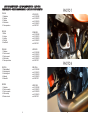
ART. 14364E
KTM 690 ENDURO R / 690 SMC R (Also fits 35kW version)
FULL SYSTEM - LV ONE EVO - STAINLESS STEEL
WARNING
DO NOT USE ORIGINAL
GRAPHITE BUSHING
19
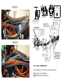
PHOTO 3
PHOTO 4

7
125
110
31
Db-Killer N.65
Cod.
3014324801R
160
e.75
e.75
370
e.45
e.54
i.54
Muffler kit
Cod.
3014364482R
Short helical
spring tensile
cod. 303949001R
S.s bushing
cod.206424R
S.s flange
cod.206423R
Manifold kit
cod. 3014364204R
OPTIONAL
cod.5683
Header pipe kit
cod. 3014364202R
M12x1.25
A
BB
A
A
A
A
A
A
A
A
A
A
Belts and rivets kit
Cod.
0814324003R
Carbon end cup set
cod.3014000701R
S.s end cup set
cod.307242711R
Outer sleeve
replacement kit
cod.3014364010R
Muffler repack kit
cod.414205R
BB
BB
A
9,5
12
4
95
52
64
73
Flange s.s. sp.5mm
cod.206423R
45
50
54,8
56
42
23
19,7
s.s. bushing
cod.206424R
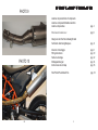
ART. 14364E - SPARE PARTS
KTM 690 ENDURO R / 690 SMC R (Also fits 35kW version)
A
FITTING KIT cod.3014364601R
B
CARBON COVER cod.308213001R
WARNING
DO NOT USE ORIGINAL
GRAPHITE BUSHING
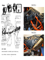
PHOTO 1
18
PHOTO 2

8
ISTRUZIONI DI MONTAGGIO
LISTA DEI COMPONENTI FORNITI:
Fare riferimento alla distinta componenti ed al disegno del prodotto presenti in questo
libretto.
ATTENZIONE:
prima di effettuare qualsiasi operazione accertarsi che la temperatura superficiale del
blocco motore e dell’impianto di scarico sia tale da non procurare danni all’operatore e/o
alle parti non resistenti al calore (carene, tubazioni, guaine ecc.).
INSTALLAZIONE:
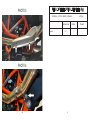
1. Asportare la carenatura completa, smontare tutto l’impianto di scarico originale.
Scollegare la sonda Lambda dall’impianto di scarico originale. (Foto 1-2-3-4-5-6)
2. Inserire la boccola nella propria sede sul cilindro, calzare la flangia nella posizione
corretta interponendo la guarnizione/boccola di grafite quando presente, avendo cura
di non serrare completamente i due dadi sui prigionieri, in modo da ottenere un corretto
posizionamento e di poter sfruttare i giochi esistenti tra la flangia ed i prigionieri del
cilindro. (Foto 7)
3. Calzare il collettore primario nella boccola precedentemente montata, verificare il loro
corretto orientamento e fissarlo alla flangia con le molle in dotazione.
4. Collegare la sonda Lambda all’impianto di scarico “LeoVince”, avvitando l’attacco
nell’apposito punto posto sul collettore finale. (Foto 8)
5. Inserire il silenziatore Leovince sul rispettivo collettore finale e dopo aver verificato il
corretto allineamento degli occhielli delle molle e del bocchettone posteriore
(uscita dei gas di scarico), vincolare le due parti con la molla in dotazione. (Foto 9)
6. Inserire il collettore finale nel collettore primario precedentemente montato e
vincolarlo con le molla in dotazione. Fissare la staffa di sostegno del collettore al telaio
mediante la minuteria in dotazione. (Foto 10)
7. Montare distanziali, rondelle e staffe di supporto (quando presenti) come indicato a
disegno e serrare il tutto con l’apposita bulloneria.
Recuperare il carter paracalore originale e montarlo sul collettore non serrare comple-
tamente le fascette originali.
I
17
7. Montar los separadores, las arandelas y los estribos de soporte (cuando están pre-
sentes) tal como se indica en el diseño y apretar todo con los bulones apropiados.
Recuperar el protector de calor original y montarlo en el colector final, no apretar del
todo los tornillos originales, y instálarlo en el colector final, no apriete del todo los tor-
nillos originales.
8. Fijar entonces la abrazadera para asegurar el acoplamiento del colector Leovince a
la tubería de la instalación original. Montar nuevamente las carenas laterales.
9. Controlar el apretado de los bulones, poner el motor en marcha, aguardar algunos
minutos hasta que se alcance la temperatura
10. Si el montaje se ha efectuado correctamente, los espacios ocupados por los colec-
tores no deberán interferir con piezas del motor (radiador, base, carenas, etc.).
ADVERTENCIA:
Durante los primeros Km. de empleo, el silenciador del escape sufrirá unos asenta-
mientos y es posible que se comprueben mínimos escapes de gas. Después de un
recorrido de aproximadamente 100 km. es necesario efectuar un control del apretado
de todos los tornillos.
REGLAJE:
La puesta a punto de este silenciador ha sido efectuada en la Fabrica Leovince sobre
un banco de pruebas electrónico, con un vehículo en perfecto estado de uso y regula-
ciones standard.
MANTENIMIENTO:
Verificar periódicamente las uniones del silenciador y todos los elementos que pue-
dan deteriorarse con el uso (material fonoabsorbente, guarniciónes y otras piezas en
goma) y substituirlas periódicamente.Para la limpieza del silenciador se puede utilizar
gasolina, gasóleo y alcohol. No se puede utilizar solventes de ningún tipo. Un eventual
cambio del color del silenciador es normal con el uso y depende de la naturaleza de los
materiales y del calor.
ESTÁ TERMINANTEMENTE PROHIBIDA
cualquier modificación y/o manipulación del silenciador de escape; en caso de realizar-
se, Belgrove Sp. z o.o. declina cualquier responsabilidad que pueda derivar de vicios,
defectos y mal funcionamiento del producto manipulado y/o modificado.
Aconsejamos de efectuar el montaje cam el ayudo de un expecialista

9
8.Fissare quindi la fascetta per assicurare l’accoppiamento del collettore Leovince alla
tubazione dell’impianto originale. Rimontare le carene laterali.
9. Verificare il serraggio della bulloneria, avviare il motore, attendere alcuni minuti che
sia raggiunta la temperatura di funzionamento e verificare che non vi siano fughe di gas.
10. Se il montaggio è effettuato correttamente, gli ingombri dei collettori non devono
interferire con parti del motore (radiatore,
basamento, carene ecc.).
REGOLAZIONE:
la messa a punto di questo silenziatore è stata effettuata nello stabilimento Leovince
su banco di prova elettronico con un veicolo in perfetto stato di utilizzo e regolazioni
standard.
MANUTENZIONE:
verificare periodicamente gli attacchi del silenziatore e tutti gli elementi che possono
deteriorarsi con l’uso (materiale fonoassorbente, guarnizioni e altre parti in
gomma) e provvedere alla loro periodica sostituzione. Per la pulizia del silenziatore é
possibile utilizzare benzina, gasolio ed alcool. Non possono essere usati solventi di
alcun tipo. Un eventuale cambiamento del colore del silenziatore è dato da un utilizzo
normale e dipende dalla natura dei materiali e dal calore.
E’ VIETATA ogni modifica o manomissione del silenziatore di scarico; qualora eseguita,
la Belgrove Sp. z o.o. declina ogni responsabilità derivante da vizi, difetti e cattivo
funzionamento del prodotto manomesso o modificato.
É consigliato per il montaggio l’ausilio di personale specializzato
INSTRUCCIONES DE MONTAJE
LISTA DE COMPONENTES SUMINISTRADOS:
Comprobar la lista de componentes con el dibujo del producto presente en este manual.
PRECAUCIONES:
Antes de efectuar cualquier operación, hay que asegurarse de que la temperatura su-
perficial del silenciador del escape no pueda causar daños al operario y/o a las piezas
que no resisten el calor (carenas, tuberías, vainas etc.).
MONTAJE:
1. Extraer el carenado completo,esconectar la sonda Lambda del silenciador del esca-
pe original. Desmontar todo el silenciador del escape original. (Fotos 1-2-3-4-5-6)
2. Insertar los casquillos en sus asientos en los cilindros, calzar las bridas en la posi-
ción correcta (interponiendo la guarnición/casquillo de grafito cuando presente), con la
precaución de no apretar completamente las dos tuercas sobre los pernos prisioneros,
para obtener así un correcto posicionamiento y poder aprovechar los juegos existentes
entre la brida y los pernos prisioneros del cilindro. (Foto 7)
3. Calzar el colector primario en el casquillo montado precedentemente, comprobar su
correcta orientación y fijarlo a la brida con los muelles en dotación.
4. Conectar la sonda Lambda al silenciador del escape “LeoVince”, atornillando la
unión en el correspondiente punto situado en el colector final. (Foto 8)
5. Insertar el silenciador Leovince sobre el colector final, después de haber verificado
la correcta alineación de las argollas de los muelles y de la boca trasera (salida de los
gases de escape), conectar las dos partes con el/los muelle/s en dotación. (Fotos 9)
6. Introducir el colector final en los colectore primarios montados precedentemente y
vincularlo con los muelles en dotación. Fijar el soporte del colector al bastidor de la
motocicleta con el tornillo suministrado.(Foto 10)
E
16

10
FITTING INSTRUCTION
LIST OF SUPPLIED PARTS:
Refer to the list of components and the product drawing included in this booklet.
WARNING:
before carrying out any work on the exhaust, check that its surface has cooled so that
it will not damage components, which are not heat-resistant (such as fairing, hoses,
rubber sleeves, etc.), or the operator.
INSTALLATION:
1. Remove the fairing completely, remove the entire original exhaust system.
Disconnect the Lambda probe from the original exhaust system. (Photos 1-2-3-4-5-6)
2. Put the bushing into its seat on the cylinder, fit the flange to the right position, and
remembering to fit the sealing gasket when available. Partially tighten the two nuts on
the mounting studs to allow a degree of realignment. This is made possible by the clea-
rance between the flange and the mounting studs on the power unit. (Photo 7)
3. Fit the primary manifold into the previously mounted bushing, check its orientation is
correct and then secure them to the flanges with the supplied springs.
4. Connect the Lambda probe to the “LeoVince” exhaust system, by tightening its con-
nection to the proper position on the end manifold (Photo 8)
5.Slide the Leovince silencer onto the final link pipe, check the alignment of the moun-
ting eyes for the springs and the alignment of the exhaust outlet to the rear of the silen-
cer, and then link the parts together with the springs provided (Photo 9)
6. Insert the final manifold into the previously assembled primary manifold and
secure it with the supplied springs. Attach the manifold support bracket to the motor-
cycle frame using the supplied screw. (Photo 10)
7. Mount spacers, washers and brackets (if any) as shown on the drawing and then
secure by tightening nuts and bolts.
Recover the original heat shield and fit it to the collector, do not tighten the original
clamps completely.
GB
15
7. Montieren Sie die Abstandhalter, die Unterlegscheiben und die Stützbügel (falls
vorhanden) und befestigen Sie alles mit den mitgelieferten Schrauben (siehe Zeich-
nung). Montieren Sie das originale Hitzeschild an dem Verbindungsrohr, ohne die origi-
nalen Schellen bereits komplett festzuziehen.
8. Danach die Schelle/n befestigen, um die Verbindung des/der Leovince-Krümmer/s
mit dem/den Rohr/en der Originalanlage sicherzustellen. Die Seitenverkleidungen wie-
dermontieren.
9. Den festen Sitz der Verschraubungen prüfen, den Motor anlassen und kurz danach,
sobald die Betriebstemperatur erreicht ist, prüfen, daß kein Gas austritt.
10. Bei ordnungsgemäßer Montage, kommt der Auspuff nicht mit den Motorteilen in
Berührung (Kühler, Motorblock,
Gehäuse usw.).
ZUR BEACHTUNG:
Während der ersten gefahrenen km fährt sich die gesamte Auspuffanlage ein und es ist
möglich, daß sich minimale Gasaustritte bemerkbar machen. Nach etwa 100 km Fahrt
müssen alle Schrauben überprüft werden und ggf nachgezogen werden.
EINSTELLUNG:
Die Vergasereinstellung bei der Montage dieses Schalldämpfers wurde im Leovin-
ce-Werk auf einem elektronischen Prüfstand mit einem Fahrzeug in perfektem Benut-
zungszustand und mit der vom Werk vorgesehenen Regulierung vorgenommen.
WARTUNG:
Bitte überprüfen Sie in regelmäßigen Abständen die Anschlüsse des Schalldämpfers
und alle verschleißanfälligen Elemente (Schalldämmungsmaterial, Dicthungen u. ande-
re Gummiteile) und die von Zeit zu Zeit austauschen. Zur Reinigung des Schalldämp-
fers Benzin, Gasöl oder Alkohol benutzen. Keine Lösemittel verwenden. Eine eventuel-
le Verfärbung des Schalldämpfers kann beim normalen Gebrauch auftreten und ist
kein Grund zur Reklamation
VERBOTEN IST jegliche Veränderung bzw. Eingriffe am Auspuff-Schalldämpfer: bei
Zuwiderhandlung lehnt Belgrove Sp. z o.o. jegliche Verantwortung infolge von Schäd-
en, Defekten und mangelnder Funktionsfähigkeit des veränderten Produktes ab.
Wir empfehlen, dass die montage mit der hilfe von spezialisten durchgeführt wird

11
8.Tighten the various clamps which join the Leovince link pipe to the OE exhaust hea-
ders Replace the side fairings..
9.Check the tightening of nuts and bolts. Start the engine, wait a few minutes until the
correct running temperature has been reached and check there is no gas leakage.
10. If assembly has been correctly undertaken, the overall dimensions of the manifolds
should not interfere with the engine parts (radiator, cylinder block, fairings, etc.).
IMPORTANT:
During the first km of running, the exhaust system needs breaking-in; therefore, slight
gas leakage might occur. After approximately 100 Km, check all the fasteners.
ADJUSTEMENT:
This silencer has been developed by Leovince on an electronic dynamometer using a
vehicle in perfect condition, and in standard trim
MAINTENANCE:
From time to time, check all the brackets and fasteners, which could be affected by use
(sound-deadening material, seals and other rubber parts) and replace them periodically.
The silencer may be cleaned using gasoline, diesel oil or alcohol. Absolutely avoid the
use of any kind of solvent.It is normal for there to be some discolouration of the silencer,
which is the result of heat and the nature of the materials used.
IT IS FORBIDDEN to modify silencers. Whatever form this may take,
Belgrove Sp. z o.o. declines any responsibility for defects, problems, or malfunction,
arising from the use of any product which has been modified or tampered with.
We suggest the fitting to be made by professionals
14
MONTAGEANLEITUNGEN
BESTANDTEILE-LISTE:
Maßgeblich ist die in diesem Heft enthaltene Komponentenliste und die Zeichnung des
Produktes.
VORSICHTSMASSNAHMEN:
Bitte vergewissern Sie sich vor jeder Benutzung , daß die Oberflächentemperatur der
Auspuffanlage keine Gefahr für den Benutzer bzw. für die nicht hitzebeständigen Teile
(Verkleidungen, Leitungen, Ummantelungen usw.) darstellt.
MONTAGE:
1. Die komplette Seitenverkleidung entfernen, Die komplette Original-Auspuffanlage
abmontieren. Lambda-Sonde von der Original-Auspuffanlage trennen.
(Bilder 1-2-3-4-5-6)
2. Die Buchsen in die dafür vorgesehenen Sitze an den Zylindern einsetzen, die Flan-
schen in die richtige Position setzen (durch Zwischenlegen von Dichtung/Graphitbu-
chse falls vorhanden), wobei darauf zu achten ist, daß die beiden Muttern auf den
Stiftschrauben nicht vollständig festgezogen werden, so daß eine korrekte
Positionierung erzielt wird und das Spiel zwischen Flansch und Stiftschrauben des
Zylinders genutzt werden kann. (Bilder 7)
3. Den Primär-Auspuffkrümmer in die zuvor montierte Buchse einsetzen, auf richtige
Ausrichtung prüfen und durch die beigefügten Federn an dem Flansch befestigen.
4. Die Lambda-Sonde an die “LeoVince”-Auspuffanlage anschließen. Dabei ist der An-
schluß in den dafür vorgesehenen (Bilder 8)
5. Den Leovince -Schalldämpfer am entsprechenden Krümmer einsetzen und prüfen,
ob die Ösen der Federn und des hinteren Stutzens (Austritt der Abgase) auf einer Linie
liegen. Die beiden Teile mit der/den mitgelieferten Feder/n befestigen. (Bilder 9)
6. Das Endauspuffrohr in die zuvor montierten Primär-Auspuffkrümmer einsetzen und
es durch die beigefügten Federn befestigen. Befestigen Sie die am Sekundär-Auspuff-
krümmer angeschweißte Halterung mit der mitgelieferten Schraube am Motorradrah-
men. (Bilder 10)
D

12
NOTICE DE MONTAGE
LISTE DES PIECES FOURNIES:
Se référer à la liste des pièces et au croquis du produit inclus dans cette
notice .
ATTENTION:
Avant d’effectuer toute opération, vérifier que le pot d’échappement
est bien froid afin d’éviter toute brûlure et toute détérioration aux pièces (carénage,
tubes, gaines, etc.).
MONTAGE:
1. Déposer le carénage complet, demonter tout l’équipement d’échappement d’origine
Débrancher la sonde Lambda de l’équipement d’échappement d’origine.
(Photos 1-2-3-4-5-6)
2. Insérer la bague sur le siège du cylindre, placer correctement les bride et en faisant
attention à ne pas serrer complètement les deux écrous sur les goujons
de façon à avoir un positionnement optimal, et à pouvoir exploiter les
jeux existants entre la bride et les goujons du cylindre. (Photo 8)
3. Emboîter ensuite le collecteur primaire dans la bague précédemment montées, vérif-
ier son orientation et le fixer sur la bride à l’aide des ressorts fournis.
4. Raccorder la sonde Lambda à l’équipement d’échappement “LeoVince”, en vissant
le raccord sur le point spécifique du collecteur final. (Photo 8)
5. Installer le silencieux Leovince sur le collecteur final et après avoir vérifié le bon
alignement des ressorts et du tube arrière (sortie de gaz d’échappement), bloquer les
deux parties avec le ressort fournis. (Photos9)
6. Insérer le collecteur final dans les collecteurs primaire précédemment montés et le
fixer à l’aide des ressorts fournis. Fixer la patte de fixation entre l’échappement et le
cadre de moto à l’aide de la vis fournie. (Photo 10)
F
13
7. Monter les entretoises, les rondelles et les étriers de support (lorsque prévus) selon
le schéma, et serrer donc tout l’ensemble par la boulonnerie fournie.
Récupérer le pare-chaleur d’origine et installer-le sur le collecteur final, ne serrer pas
complètement les attaches d’origine.
8. Fixer ensuite la collier pour assurer l’emboîtement du collecteur Leovince au col-
lecteurs d’origine. Monter le carénage latéral.
9. Vérifier le serrage de la boulonnerie, lancer le moteur, attendre quelques minutes que
la température de fonctionnement ait été atteinte et vérifier l’absence de fuites de gaz.
10. Si le montage a été correctement effectué, les dimensions des collecteurs ne doi-
vent pas interférer avec toute partie du moteur (radiateur, carter cylindre, carènes, etc.).
IMPORTANT:
Pendant les premiers km d’utilisation, l’échappement se positionnera. Il est possible
qu’il y ait de légères fuites de gaz. Un contrôle du serrage de tous les boulons doit être
fait après 100 km.
REGLAGE:
La mise au point de ce silencieux est faite dans l’usine Leovince sur un banc d’essai
électronique avec un véhicule en parfait état de marche et des réglages standards.
ENTRETIEN:
Vérifier périodiquement les fixations du silencieux et tous les éléments susceptibles
de s’abîmer avec le temps (matériau de fonoabsorption, joint et autres piéces en ca-
outchouc) et les remplacer périodiquement.Pour le nettoyage du silencieux, on peut
utiliser de l’essence, du gazole ou de l’alcool. Absolument éviter tout type de solvable
solvant. Un éventuel changement de couleur du silencieux est dû à une utilisation nor-
male et provient de la nature des matériaux et de la chaleur.
IL EST ABSOLUMENT INTERDIT de modifier le silencieux d’échappement; dans le cas
contraire, Belgrove Sp. z o.o. décline toute responsabilité.
Nous conseillons d’effectuer le montage a l’aide personnel specialise
-
 1
1
-
 2
2
-
 3
3
-
 4
4
-
 5
5
-
 6
6
-
 7
7
-
 8
8
-
 9
9
-
 10
10
-
 11
11
-
 12
12


dans d''autres langues
- italiano: LeoVince 14364E Manuale utente
- English: LeoVince 14364E User manual
- español: LeoVince 14364E Manual de usuario
- Deutsch: LeoVince 14364E Benutzerhandbuch
- português: LeoVince 14364E Manual do usuário
Documents connexes
-
 LeoVince KTM 690 Manuel utilisateur
-
LeoVince 3399E Manuel utilisateur
-
 LeoVince Nero Yamaha 14077 Manuel utilisateur
-
LeoVince 14399 Mode d'emploi
-
LeoVince 15250FB Manuel utilisateur
-
LeoVince 14066 Manuel utilisateur
-
LeoVince 15242 Manuel utilisateur
-
LeoVince 15400B Manuel utilisateur
-
 LeoVince LV-10 Manuel utilisateur
-
 LeoVince 14395E Manuel utilisateur


