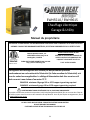
Dura Heat EWH5500 Manuel utilisateur
- Catégorie
- Chauffe-eau
- Taper
- Manuel utilisateur

EWH5510 / EWH9615
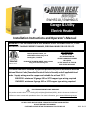
Installation Instructions and Operator's Manual
UL 2021. FIXED AND LOCATION –DEDICATED ELECTRIC ROOM HEATERS
DO NOT DISCARD THIS MANUAL
CUSTOMER: PLEASE RETAIN THIS MANUAL FOR FUTURE USE
WARNING! IF THE INFORMATION IN THIS MANUAL IS NOT FOLLOWED EXACTLY, A FIRE
MAY RESULT CAUSING PROPERTY DAMAGE, PERSONAL INJURY OR LOSS OF LIFE.
Comfort Home Products, Inc.
12256
William Penn Hwy, Ste A
Huntingdon, PA 16652
Made in China
DURA HEAT PHONE NUMBER: (800) 776-9425
http://www.worldmkting.com
FOR YOUR SAFETY
DO NOT STORE
OR USE GASOLINE OR
OTHER FLAMMABLE VAPORS
OR LIQUIDS
IN THE VICINITY OF THIS OR
ANY OTHER APPLIANCE
CALIFORNIA RESIDENTS ONLY-WARNING:
This product contains chemicals including di(2-ethylhexyl)phthalate (DEHP), which is known to the State of
California to cause cancer and reproductive harm. For more information, go to: www.P65Warnings.ca.gov
This heater should be installed by qualified persons only and in accordance with the
National Electric Code (Canadian Electrical Code in Canada) and all applicable local
codes. Supply wiring must be copper and suitable for at least 75° C.
EWH5510- minimum 10 gauge SJO or SJTO copper type wiring required
EWH9615- minimum 6 gauge SJO or SJTO copper type wiring required.
Garage & Utility
Electric Heater
2022-10-19


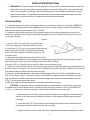
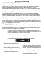
IMPORTANT INSTRUCTIONS
PLEASE READ AND SAVE THESE IMPORTANT SAFETY INSTRUCTIONS
WHEN USING ELECTRIC APPLIANCES, BASIC PRECAUTIONS SHOULD ALWAYS BE FOLLOWED TO REDUCE
THE RISK OF FIRE, ELECTRIC SHOCK, AND INJURY TO PERSONS, INCLUDING THE FOLLOWING:
1.
Read all instructions before using this heater.
2.
This heater is hot when in use. To avoid burns, do not let bare skin touch hot surfaces. If provided, use
handles when moving this heater. Keep combustible materials, such as furniture, pillows, bedding, papers,
clothes and curtains at least 3 feet (0.9m) from the heater.
3.
Extreme caution is necessary when any heater is used by or near children, pets or invalids and
whenever the heater is left operating unattended.
4.
Do not operate any heater with a damaged cord or plug or after the heater malfunctions, has been
dropped or damaged in any manner. Disconnect power at service panel and have heater inspected and or
repaired by a qualified service person.
5.
Do not use outdoor.
6.
Under no circumstances should this appliance be modified. Parts having to be removed for servicing
must be replaced prior to operating this appliance again.
7.
This heater is intended for comfort heating applications and not intended for use in special
environments. Do not use in damp or wet locations such as marine or greenhouse or in areas where
corrosive or chemical agents are present.
8.
To disconnect heater, first turn controls to off, and turn off power to heater circuit at main
disconnect
panel.
9.
Do not insert or allow foreign objects to enter any ventilation or exhaust opening as this may cause an
electrical shock or fire, or damage the heater.
10.
To prevent a possible fire, do not block air intakes or exhaust in any manner. Do not use on soft
surfaces, like a bed, where openings may become blocked.
11.
This appliance has hot and arcing or sparking parts inside. Do not use it in areas where gasoline, paint
or flammable liquids are used or stored.
12.
Use this heater only as described in this manual. Any other use not recommended by the
manufacturer may cause fire, electric shock, or injury to persons.
13.
This heater is not to be used as a portable unit and or have a cord and plug installed. (HARD WIRED
ONLY)
14.
This heater is provided with automatic resetting thermal limit and an alarm beeper to alert user if
heater has overheated. If the alarm has activated, immediately turn off the heater and inspect and
remove any objects around heater that may have blocked the airflow or otherwise caused the heater to
overheat. Do not continue to use heater if it repeatedly overheats and activates the alarm. DO NOT
OPERATE THE HEATER WITH THE ALARM SOUNDING (FLASHING).
CAUTION - Once heater has cycled off on the thermal limit, the heater will not return to operation until
the user restarts and reprograms the control. Therefore, this unit is not recommended for freeze
protection applications.
15.
When installing, see INSTALLATION INSTRUCTIONS for additional warnings and precautions.
16.
For safe and efficient operation, and to extend the life of your heater, keep your heater clean - See
MAINTENANCE INSTRUCTIONS.
SAVE THESE INSTRUCTIONS
1

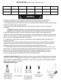
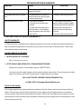
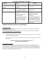
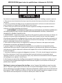
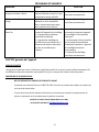
SPECIFICATIONS (All Specifications -5%/-10% tolerance)
Model No
Volts/Hertz
Amps
Watts
BTU/HR
Phase
Minimum
Circut
EWH5510
240V/60HZ
21
5000
17060
1
30
EWH9615
240V/60HZ
42
10000
34120
1
50
To prevent a possible fire, injury to persons or damage to the heater, adhere to the following:
1.
Disconnect all power coming to heater at main service panel before wiring or servicing.
2.
All wiring procedures and connections must be in accordance with the National and Local Codes having
jurisdiction and the heater must be grounded.
3.
Verify the power supply voltage coming to heater matches the ratings as shown on the heater
nameplate.
CAUTION: ENERGIZING HEATER AT A VOLTAGE GREATER THAN THE VOLTAGE PRINTED ON THE
NAMEPLATE WILL DAMAGE THE HEATER AND VOID THE WARRANTY AND COULD CAUSE A FIRE.
4.
CAUTION: High temperature, risk of fire, keep electrical cords, drapery, furnishings, and other
combustibles at least 3 feet (0.9 m) from front of heater. Do not install heater behind doors, below towel
racks, or in an area where it is subject to being blocked by furniture, curtains or storage materials. Hot air
from the heater may damage certain fabrics and plastics.
5.
To reduce the risk of fire do not store or use gasoline or other flammable vapors and liquids in the
vicinity of the heater.
6.
When heater is to be wall or ceiling mounted, the anchoring provision must be sufficient strength to
support the total weight of the heater plus the weight of the mounting provisions. Failure to properly
secure the supporting members of the building structure could allow the heater to fall.
7.
The following minimum clearances must be maintained: 30° Tilted, Bottom of Heater to Floor: 6’ (1.8
M) minimum, 11’ (3.3 M) recommended maximum Horizontal Airflow, Bottom of Heater to Floor: 6’ (1.8
M) minimum, 8’ (2.4 M) recommended maximum Side of heater to adjacent wall: 6” (13 mm)
8.
Do not use this heater for drying out paint, plaster, sawdust and drywall sanding dust as this
will permanently damage the heater and must be kept out of the heater.
Unpacking Your New Heater: Remove heater from box, locate parts bag in packing material, and inspect
to make sure heater is not damaged or missing parts. If damaged or parts are missing, call our Technical
Service Hotline at 1-800-776-9425 for assistance. Do not return to store where purchased until you first
call the above number for assistance.
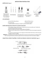
HARDWARE INCLUDED: Figure 1
2

INSTALLATION INSTRUCTIONS
TOOLS NEEDED:
•
Phillips head screwdriver
•5/32 in. or 4 mm drill bit
•
Power Drill
•Stud Finder
•
The remote control is powered by 2 AAA batteries. Batteries are NOT included
HARDWARE REQUIRED FOR WIRING HEATER:
•
Adequate gauge and length of copper wire (2 power conductors plus ground) suitable for application
to route electrical panel to heater
•
Suitable Junction Box and connectors as required for application
•
Appropriate size wire nuts for connection branch circuit wires to pigtails.
•
A length of flexible conduit (or as required by the NEC and local codes) to route power to heater.
NOTE:
Hardware supplied is intended for installation into wood framing only. If installation into other type of construction,
additional hardware will be required for correct installation.
CONNECTORS, CABLE AND HARDWARE USED TO WIRE THE HEATER: Figure 2
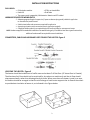
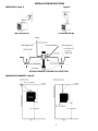
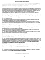
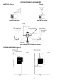
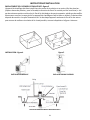
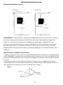
LOCATING THE HEATER: Figure 3
The heater should be installed out of traffic areas and at least 6' off the floor. (8” above floor in Canada)
The direction of air flow should not be restricted (ie: by columns or machinery) and the air flow should
wipe exposed walls, rather than blowing directly at them. When more than one heater is used in an area,
the heaters should be arranged so that the air discharge of each heater supports the air flow of the others
to provide best circulation of warm air, as indicated in the Figure below.
3

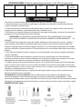
WALL MOUNTING
CEILING MOUNTING
INSTALLATION INSTRUCTIONS
MOUNTING: Figure 4 Figure 5
DETAILED BRACKET ASSEMBLY ILLUSTRATION
MINIMUM CLEARANCES: Figure 6
4

INSTALLATION INSTRUCTIONS
•WARNING: Fall Hazard - Heater must be attached to a joist with 3 screws (two at keyhole slots and
third safety screw at center hole) to prevent heater from possibly falling. The screws provided with
heater are intended for installing in wood framing only and not intended for metal joists or other
types of construction. If installation into other type of construction, additional hardware will be
required for correct installation. All hardware must be tightened securely.
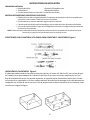
HEATER MOUNTING:
1.
Locate the wood stud or joist in ceiling and mark line in location for heater to be installed. NOTE: The
wall/ceiling mounting bracket allows installation onto a wall or ceiling using the specific mounting holes
and minimum clearances as shown in Fig 4, 5, 6 and 7.
2.
Determine the desired location for mounting making sure the minimum clearances as noted in this
manual are maintained and using the bracket as a template, mark the two keyhole locations on the wall
or ceiling for drilling.
Figure 7
3.
Use the 5/32 in. (4 mm) drill bit to pre-drill two
holes
for screws at the locations marked in step 2.
4.
Install two 2.5” (65 mm) screws into the holes leaving
approximately 1/8” of the screw offset from the wall.
Ensure that both screws are inserted at least 1.5” into
the stud or joist.
5.
Hook the mounting bracket onto the wall (or ceiling)
by fitting the two keyholes on the bracket over the two screws and pushing the bracket down into place.
Mark the location of the center (3rd safety) hole onto the wall or ceiling.
6.
Use the 5/32 in. (4 mm) drill bit to pre-drill a hole for the 3rd safety screw.
7.
Attach the heater handle bracket to the heater using the two screws and washers preassembled to the
top of the heater making sure the smaller hole in bracket faces the rear of heater. Remove the screws and
then attach bracket making sure both screws are tight.
8.
Attach the wall/ceiling bracket to the heater using the larger 20 mm (.8”) bolt, two flat washers and
lock nuts as shown in Fig. 5. To prevent rotation, a small M10 mm bolt and nut are provided in the parts
bag. Assemble this smaller screw into the small hole through wall bracket and heater bracket as shown
in Fig. 5. and securely tighten both bolts.
9.
Attach the heater and mounting bracket assembly to the wall (or ceiling):
CAUTION - The keyhole slots are provided to assist in the installation by temporarily supporting
the heater until the third safety screw is installed into the 3rd hole in bracket. Failure to install the 3rd
safety
screw in the center hole location in the bracket could allow the heater to fall.
a.
Hook bracket onto the two screws (installed at Step 4) by fitting heater and wall/ceiling
bracket on the two screws through the keyholes on the bracket and pushing the bracket
into place.
b.
Insert the third 2.5” (65 mm) safety screw through the center hole on the bracket and
into the pre-drilled hole (Step 6) in the wall or ceiling.
c.
Tighten all three screws to secure the mounting bracket and heater assembly to the wall.
5

WIRING SUPPLEMENT FOR 220/240V
After heater has been properly mounted
to the
building structure and appropriate
branch circuit
wiring has been routed to
the heater location in
accordance with the
National Electrical Code and
local codes,
the heater is now ready for the heater to
be connected to the branch circuit.
Risk of Electric Shock or Fire
Make sure electric power is disconnected
at main
electrical panel before attempting
to connect heater
to branch circuit. Verify
branch circuit voltage is
same as noted on
heater nameplate. Connecting
heater to a
voltage greater than the heater
nameplate rating could damage the
heater and
cause a fire.
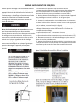
Heater is provided with a 28.3mm hole into wiring
compartment for routing of branch circuit conductors.
Appropriate conduit and fittings must be provided for
correct and safe installation.
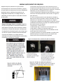
1.
Remove the field wiring cover located on bottom of
heater by removing two screws. See Figure 8 for reference.
2.
Bring branch circuit conductors to heater and into
the
heater box. Install appropriate
cable clamp on the
heater as shown in Figure 9.
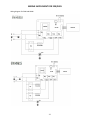
3.
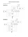
Following the wiring diagrams in Figure 10 connect the
supply wiring to the power block inside the wiring
compartment.
•
Green pigtail - connect to earth ground
•
Black pigtail - connect to branch circuit L (1)
•
White pigtail - connect to branch circuit L (2)
4.
Replace wiring box cover with two screws previously
removed.
5.
Adjust louvers to desired position; louvers are
designed
so that they cannot be completely closed. Do not
attempt
to defeat this safety feature.
6

WIRING SUPPLEMENT FOR 220/240V
Wiring diagram for 5KW and 10KW
7

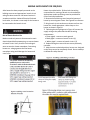
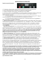
Heater Control Panel:
OPERATING INSTRUCTIONS
1.
Heater must be properly installed and correctly wired before operation.
2.
Turn power supply to heater “ON” at main switch panel.
3.
Once the heater has power, the red POWER light will be on.
4.
Pushing the red POWER button will turn the heater ON and OFF. When this button is pressed, the
heater and fan will immediately come on and the digital display will flash approximately 5 seconds.
a.
If the room temperature is lower than 65°F, the heater will continue to run until the room
temperature reaches 65°F and the heater will then cycle on and off to maintain approximately this room
temperature.
b.
If the room temperature is higher than 65°F, the display window will show 65 and flash 5 times
and the heater and fan will stop.
5.
Adjusting Power Level: While the unit is ON, push the green mode button once. This will activate the
power selection mode and the red light over the “Fan” or “Heat” will be flashing to show the current
setting. To change from Heat to Fan or Fan to Heat, use the UP or DOWN Arrow buttons. After
approximately 5 seconds the control will then be programmed for the selected output. (For model
EWH5510)
Adjusting Power Level: While the unit is ON, push the green mode button once. This will activate the
power selection mode and the red light over the “L” or “H” will be flashing to show the current setting.
To change from High to Low or Low to High, use the UP or DOWN Arrow buttons. After approximately 5
seconds the control will then be programmed for the selected output. Note: To save energy, the heater
will automatically adjust the power output to low power when room temperature is 2°F below the set
point temperature. (For model EWH9615)
6.
Adjusting temperature: While the heater is ON, push the green mode button twice. This will activate
the temperature selection mode and the digital display will flash with the current setting. To adjust, use
the UP or DOWN button until the desired temperature shows on the display. After 5 seconds the display
will change back to displaying the room temperature.
7.
Setting Time On Feature: Note: If this feature is not selected, the heater will continue to operate to
maintain the desired temperature. This feature allows the heater to operate for only a predetermined
time. While the heater is ON, push the green mode button three times. This will activate the timer mode
and the display will flash with “0H”. By pressing the UP or DOWN Arrow buttons, the display will show
the number of hours the timer will allow the heater to remain on (1H-9H where 1H = 1 hour, and 9H = 9
hours). After 5 seconds, the controller will lock in the setting.
8.
Once the controller has been programmed, the heater will cycle on and off to maintain the desired
room temperature. To help extend the life of the heater, after the heater has reached the desired
temperature and the controller turns off the heating element, the fan will continue to operate for
approximately 3 minutes to cool down the heater. This fan delay off feature also occurs when the
heater
POWER button is pushed to turn off the heater while it is heating. The fan will continue to run
to cool
down the heater.
9.
To turn off the heater, push the red POWER button. If the heater is operating, the heater will turn off,
but the fan will continue running for approximately 3 minutes to allow the heater to cool.
8

OPERATING INSTRUCTIONS
NOTE: The first time you operate the unit, it may smoke slightly. This is due to the residual cleaning agents
used to clean the element when the heater is manufactured. This is normal and does not indicate a
problem with the unit. This condition will stop after the heater has been in operation for a few minutes.
Automatic Thermal Limit: This heater is equipped with a thermal limit which will automatically shut off
the heater in the event of overheating. Should the thermal limit activate an ALARM will be activated. The
alarm will be a beeping sound; the display will show “E3” and the red “POWER” light will flash. The cause
of the overheating should be determined before further operation. As the heater cools, the thermal limit
will automatically reset the display will show “E3” indicating the heater is non-operational. Should the unit
overheat and activate the thermal limit, to return heater to operating mode will require user to press
power button on remote or heater after allowing the heater to cool for 15-20 minutes user must reset
control to desired wattage output and room temperature. Do not continue to use heater if it repeatedly
overheats to cycle the safety thermal limit as this could lead to permanent damage to heater or a fire.
Automatic Fan Delay: The heater is provided with an automatic fan off delay. As the room ambient
reaches the preset temperature level of the heater control will de-energize the heating element within
the heater while the fan continues to run for approximately 3 minutes to allow the heater to cool.
MAINTENANCE
USER CLEANING INSTRUCTION:
1.
Turn off power to heater
2.
After the heater has cooled, a vacuum cleaner with brush attachment may be used to remove dust and
lint from exterior surfaces of the heater including the grille opening. Compressed air may also be used to
blow out dust from inside heater.
3.
With a damp cloth, wipe dust and lint from grille and exterior surfaces. Be careful not to let the water
enter the inside of appliance.
4.
To protect the enclosure, don’t splash water onto the heater, and never use solvents to clean the
heater.
5.
Return power to heater and check to make sure it is operating properly.
Maintenance Cleaning Instructions:
(To be performed only by Qualified Service Personnel)
At least annually, the heater should be cleaned and serviced by a qualified service person to assure safe
and efficient operation. After completing the cleaning and servicing, the heater should be checked for
proper operation.
The remote control is powered by 2 AAA batteries. These should be replaced periodically or at least
annually.
9

TROUBLESHOOTING & WARRANTY
PROBLEM
CAUSE
SOLUTION
Fan stays on when heat shuts off.
1. Fan delay cycles On/Off until
elements are cool
1. Heater is operating correctly.
Heating element does not glow
red
1. Heating element is made of
stainless steel and will not glow
red to produce heat.
1. Heater is operating correctly.
Do not feel heat or air flow
1.
No Power to heater
2.
Desired room temperature
reached.
3.
Heater does not heat area in
front of heater; it will disperse
heat throughout room and heat
entire space.
1.
Check power connections /
connect heater to power supply.
2.
Thermostat will shut off once
desired room temperature is
reached. Heater is operating
correctly.
3.
Heater is operating correctly.
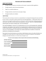
PORTABLE ELECTRIC HEATER WARRANTY
LIMITED WARRANTY:
A limited warranty is extended to the original purchaser of this heater and warrants against malfunction
due to manufacturing defects for a period of (1) one year from the date of retail purchase. Please read
and follow all details noted below.
CLAIMS HANDLED AS FOLLOWS:
1.
WITHIN 30 DAYS OF PURCHASE:
Return to the place of purchase.
2.
AFTER 30 DAYS AND WITHIN THE 1 YEAR WARRANTY PERIOD:
Contact our Customer Service Department at 1-800-776-9425.
You must have the model number, serial number and date of purchase. They will provide you with
further instructions, which will include repair or replacement at our option.
CALL 1-800-776-9425 FOR SERVICE (9AM-5PM MON.-FRI.)
or EMAIL US AT techsupport@worldmkting.com
DUTIES OF THE OWNER:
This heating appliance must be operated in accordance with the written instructions furnished with this
heater. This warranty shall not excuse the owner from properly maintaining this heater in accordance
with the written instructions furnished with this heater. A bill of sale, cancelled check or payment record
must be kept to verify purchase date and establish warranty period. Original carton should be kept in case
of warranty return of unit.
10

WHAT IS NOT COVERED:
TROUBLESHOOTING & WARRANTY
1.
Damage caused by misuse or use contrary to the owner’s manual and safety guidelines.
2.
Damage caused by a lack of normal maintenance.
3.
Repair by an unauthorized person.
4.
Damage caused by connection to an improper voltage.
5.
Damaged caused by use outdoors.
LIMITATIONS:
This warranty does not imply or assume any responsibility for consequential damages that may result from
the use, misuse, or the lack of routine maintenance of this heating appliance. A cleaning fee and the cost
of parts may be charged for appliance failures resulting from lack of maintenance. This warranty does not
cover claims, which do not involve defective workmanship or materials. FAILURE TO PERFORM GENERAL
MAINTENANCE (INCLUDING CLEANING) WILL VOID THIS WARRANTY.
THIS LIMITED WARRANTY IS GIVEN TO THE PURCHASER IN LIEU OF ALL OTHER WARRANTIES, EXPRESSED
OR IMPLIED, INCLUDING BUT NOT LIMITED TO THE WARRANTIES OF MERCHANTABILITY OF FITNESS FOR
A PARTICULAR PURPOSE. THE REMEDY PROVIDED IN THIS WARRANTY IS EXCLUSIVE AND IS GRANTED IN
LIEU OF ALL OTHER REMEDIES. IN NO EVENT WILL WORLD MARKETING OF AMERICA BE LIABLE FOR
INCIDENTAL OR CONSEQUENTIAL DAMAGES.
Some states do not allow limitations on how long an implied warranty lasts, so the above limitation may
not apply to you. Some states do not allow the exclusion or limitation of incidental or consequential
damages so the above limitation or exclusion may not apply to you.
For your record, staple your sales receipt to this manual and record the following
DATE OF PURCHASE:
PLACE OF PURCHASE:
SERIAL NUMBER:
MODEL NUMBER:
Printed in China
© 2019 Comfort Home Products, Inc. All rights reserved
11

V
EWH5510 / EWH9615
¡ADVERTENCIA! SI LA INFORMACION EN ESTE MANUAL no ES SEGUIDA EXACTAMENTE, UN RESULTADO del
FUEGO mayo que CAUSA DAÑO de PROPIEDAD, HERIDA O PERDIDA PERSONALES DE la VIDA.
Este calentador debe ser instalado solo por personas calificadas y de acuerdo con el Código
Eléctrico Nacional (Código Eléctrico Canadiense en Canadá) y todos los códigos locales
aplicables. El cableado de suministro debe ser de cobre y apto para al menos 75 °C.
EWH5510- minimum 10 gauge SJO or SJTO copper type wiring required
EWH9615- minimum 6 gauge SJO or SJTO copper type wiring required.
Comfort Home Products, Inc.
12256
William Penn Hwy, Ste A
Huntingdon, PA 16652
Hencho in China
DURA HEAT PHONE NUMBER: (800) 776-9425
http://www.worlddmkting.com
PARA SU SEGURIDAD
No ALMACENE ni UTILICE
GASOLINA ni OTROS VAPORES de
FLAMABLE ni los LIQUIDOS EN LA
ECINDAD DE ESTE niCUALQUIER
OTRO APARATO
ADVERTENCIA SOLO PARA RESIDENTES DE CALIFORNIA:
Este producto contiene elementos químicos que incluyen di(2-etilhexil) ftalato (DEHP), el cual es conocido en el
estado de California por provocar cáncer y daños en el sistema reproductivo. Para más información, vaya a:
www.P65Warnings.ca.gov
UL 2021. FIXED AND LOCATION –DEDICATED ELECTRIC ROOM HEATERS
No DESECHE ESTE MANUAL - HOJA PARA el PROPIETARIO
CLIENTE: RETENGA POR FAVOR ESTE MANUAL PARA FUTURO USO
Instrucciones de instalación y el Manual de Propietario
Espacio de trabajo forzado
calentador de aire
12

INSTRUCCIONES IMPORTANTES
LEA Y CONSERVE ESTAS INSTRUCCIONES DE SEGURIDAD IMPORTANTESAL USAR APARATOS ELÉCTRICOS,
SE DEBEN TOMAR PRECAUCIONES BÁSICAS PARA REDUCIR EL RIESGO DE INCENDIO, DESCARGAS
ELÉCTRICAS Y LESIONES A LAS PERSONAS, INCLUYENDO LO SIGUIENTE:
1.
Lea todas las instrucciones antes de usar el calentador.
2.
Este calentador alcanza altas temperaturas cuando está en uso. Para evitar quemaduras, no permita que la
piel descubierta haga contacto con superficies calientes. Si el modelo cuenta con manijas, utilícelas cada vez
que deba mover el calentador. Mantenga todo material combustible, como muebles, almohadas, ropa de
cama, papeles, ropa y cortinas, a una distancia de al menos 3 pies (1 metro) del calentador.
3.
Se debe tener suma precaución cuando se utiliza el calentador cerca de niños, mascotas o personas
discapacitadas, y cuando queda funcionando sin supervisión.
4.
No opere ningún calentador que tenga un cable o enchufe dañado o después de que haya tenido un mal
funcionamiento, se haya caído o dañado de alguna manera. Desconecte la alimentación en el panel de servicio
y haga que un técnico calificado inspeccione y repare el calentador.
5.
No lo utilice al aire libre.
6.
Este aparato no se debe modificar en ninguna circunstancia. Las piezas que deben retirarse para ser
reparadas deben reemplazarse antes de volver a utilizar este aparato.
7.
Este calentador está diseñado para aplicaciones de climatización y no para ser utilizado en entornos
especiales. No lo use en lugares húmedos o mojados, como en el mar o en invernaderos, o en áreas donde
haya presencia de agentes corrosivos o químicos.
8.
Para desconectar el calentador, primero apague los controles y desactive el circuito de alimentación del
calentador en el panel de desconexión principal.
9.
No permita que objetos extraños entren en alguna abertura de ventilación, ya que podría producirse una
descarga eléctrica o un incendio, o dañarse el calentador.
10.
Para evitar un posible incendio, no obstruya las entradas o salidas de aire. No lo use en superficies
blandas, como una cama, donde podrían obstruirse las aberturas.
11.
Este aparato contiene piezas calientes que producen chispas o arcos eléctricos. No lo utilice en áreas
donde se use o almacene combustible, pintura o líquidos inflamables.
12.
Use este calentador solo como se describe en este manual. Cualquier otro uso no recomendado por el
fabricante puede provocar incendios, descargas eléctricas o lesiones personales.
13.
Este calentador no debe usarse como una unidad portátil y no se le debe colocar un cable y un enchufe.
(SOLO CON CONEXIÓN DIRECTA)
14.
Este calentador cuenta con una protección térmica automática y con un sonido que alerta al usuario si el
aparato se ha sobrecalentado. Si se activa la alarma, apague el calentador de inmediato e inspeccione y retire
todo objeto que pueda haber obstruido el flujo de aire o que haya provocado el sobrecalentamiento. No siga
usando el calentador si se sobrecalienta y activa la alarma de forma reiterada. NO HAGA FUNCIONAR EL
CALENTADOR SI LA ALARMA ESTÁ SONANDO (INTERMITENTE).
PRECAUCIÓN: Cuando el calentador se apague debido a la protección térmica, no volverá a funcionar hasta
que el usuario reinicie y reprograme el control. Por lo tanto, esta unidad no se recomienda para aplicaciones
de protección contra congelación.
15.
Durante la instalación, consulte las INSTRUCCIONES DE INSTALACIÓN para conocer otras advertencias y
precauciones.
16.
Para un funcionamiento seguro y eficiente, y para prolongar la vida útil de su calentador, mantenga la
unidad limpia. Consulte las INSTRUCCIONES DE MANTENIMIENTO.
CONSERVE ESTAS INSTRUCCIONES
13

ESPECIFICACIONES (Todas las especificaciones tienen -5 %/-10 % de tolerancia)
Modelo No
Voltios/Hertz
Amperios
Vatios
BTU/HR
Phase
Circuito
mínimo
EWH5510
240V/60HZ
21
5000
17060
1
30
EWH9615
240V/60HZ
42
10000
34120
1
50
Para evitar un posible incendio, lesiones a personas o daños al calentador, respete lo siguiente:
1.
Desconecte todo suministro eléctrico que llegue al calentador en el panel de servicio principal antes de
realizar el cableado o mantenimiento.
2.
Todas las conexiones y procedimientos de cableado deben respetar los códigos locales y nacionales que
tengan jurisdicción. Además, el calentador debe estar conectado a tierra.
3.
Verifique que el voltaje de la fuente de alimentación que ingresa al calentador coincida con los parámetros
que figuran en la placa de identificación del calentador.
PRECAUCIÓN: SI SE ALIMENTA EL CALENTADOR CON UN VOLTAJE MAYOR QUE EL QUE FIGURA
EN LA PLACA, SE DAÑARÁ EL CALENTADOR, SE ANULARÁ LA GARANTÍA Y PODRÍA ORIGINARSE UN
INCENDIO.
4.
PRECAUCIÓN: Alta temperatura, riesgo de incendio. Mantenga los cables eléctricos, cortinas, muebles y
otros materiales combustibles a una distancia de al menos 3 pies (1 metro) del frente del calentador. No
coloque el calentador detrás de puertas, debajo de toalleros o en un área donde puedan obstruirlo muebles,
cortinas o materiales de almacenamiento. El aire caliente que emite el calentador puede dañar ciertas telas y
plásticos.
5.
Para reducir el riesgo de incendio, no almacene ni use combustible u otros vapores y líquidos inflamables
cerca del calentador.
6.
Cuando el calentador deba colocarse en la pared o el techo, el anclaje debe ser lo suficientemente
resistente para soportar el peso total del calentador más el peso de los elementos de montaje. Si no se fijan
adecuadamente los soportes a la estructura del edificio, el calentador se podría caer.
7.
Se deben mantener las siguientes distancias mínimas: 30° inclinado, Entre la parte inferior del calentador y
el piso: 6’ (1,8 m) como mínimo, 11' (3,3 m) máximo de flujo de aire horizontal recomendado, Entre la parte
inferior del calentador y el piso: 6’ (1,8 m) como mínimo, 8' (2,4 m) máximo recomendado Entre el costado del
calentador y la pared adyacente: 6” (13 mm)
8.
No use este calentador para secar, ya que el polvo del lijado de pintura, yeso, aserrín y paneles de yeso
dañará permanentemente el calentador.
Desembalaje de su nuevo calentador: Retire el calentador de la caja, busque la bolsa de piezas en el
material de empaque e inspecciónela para asegurarse de que no falten piezas o estén dañadas. Si faltan
piezas o están dañadas, llame a nuestra línea directa de servicio técnico al 1-800-776-9425 para obtener ayuda.
No regrese a la tienda donde compró el calentador sin primero llamar al número anterior para obtener ayuda.
MATERIALES INCLUIDOS: Figura 1:
14

HERRAMIENTAS NECESARIAS:
INSTRUCCIONES DE INSTALACIÓN
•
Destornillador Phillips
•Broca de 5/32 pulgadas o 4 mm
•
Taladro eléctrico
•Detector de montantes
•
El control remoto funciona con 2 pilas AAA. Las pilas NO están incluidas
MATERIAL NECESARIO PARA EL CABLEADO DEL CALENTADOR:
•
Cable de cobre con calibre y longitud adecuados (2 conductores de alimentación más tierra) apropiados para
la aplicación a fin de conectar el tablero eléctrico con el calentador
•
Caja de empalmes y conectores adecuados según lo requiera la aplicación.
•
Capuchones de conexión del tamaño adecuado para conectar cables del circuito derivado a cables flexibles.
•
Un tramo de conducto flexible (o lo que exija el Código Eléctrico Nacional y los códigos locales) para encaminar
la corriente hacia el calentador.
NOTA:
El material suministrado está destinado únicamente a la instalación en estructuras de madera. Si se instala en otro tipo de
construcción, se requerirán herrajes adicionales para una instalación correcta.
CONECTORES, CABLE Y MATERIAL UTILIZADOS PARA CONECTAR EL CALENTADOR: Figura 2
UBICACIÓN DEL CALENTADOR: Figura 3
El calentador debe instalarse fuera de las áreas de tránsito y al menos a 6’ del piso (8” por encima del piso
en Canadá). No se debe obstaculizar la dirección del flujo de aire (con columnas, maquinarias, etc.) y el
flujo de aire debería acariciar las paredes expuestas, en lugar de soplar directamente sobre ellas. Cuando
se usa más de un calentador en un área, deben colocarse de modo que la descarga de aire de cada uno sea
compatible con el flujo de aire de los otros a fin de proporcionar la mejor circulación de aire caliente, como
se indica en la siguiente figura.
15

MONTAJE EN PARED
MONTAJE EN TECHO
INSTRUCCIONES DE INSTALACIÓN
MONTAJE: Figura 4 Figura 5
ILUSTRACIÓN DETALLADA DEL SOPORTE
DISTANCIAS MÍNIMAS: Figura 6
16

INSTRUCCIONES DE INSTALACIÓN
ADVERTENCIA: Peligro de caída: El calentador debe sujetarse a una viga con 3 tornillos (dos en los orificios de
los extremos y el tercer tornillo de seguridad en el orificio central) para evitar que se caiga. Los tornillos
provistos con el calentador están diseñados para ser colocados solo en estructuras de madera y no en vigas
metálicas u otros tipos de construcción. Si se instala en otro tipo de construcción, se requerirán herrajes
adicionales para una instalación correcta. Todos los herrajes deben ajustarse firmemente.
MONTAJE DEL CALENTADOR:
1. Localice el montante de madera o la viga en el techo y marque una línea en la ubicación donde se colocará
el calentador. NOTA: El soporte de montaje en pared/techo permite la colocación en una pared o techo
utilizando los orificios de montaje específicos y las distancias mínimas como se muestra en las Fig. 4, 5, 6 y 7.
2. Determine la ubicación deseada para el montaje asegurándose de respetar las distancias mínimas indicadas en este
manual. Utilice el soporte como guía, marque la ubicación de los dos orificios externos en la pared o el techo para
realizar las perforaciones.
Figura 7
3.
Utilice la broca de 5/32 pulgadas (4 mm) y perfore
dos orificios para tornillos en los lugares que se marcaron
en el paso 2.
4.
Coloque dos tornillos de 2,5” (65 mm) en los orificios
Dejando aproximadamente 1/8” del tornillo fuera de la
pared. Asegúrese de que ambos tornillos se hayan introducido
al menos 1,5” en la viga o montante.
5.
Enganche el soporte de montaje en la pared (o el techo) colocando los dos orificios sobre los dos tornillos y
empujando el soporte para acomodarlo en su lugar. Marque la ubicación del orificio central (tercera
seguridad) en la pared o el techo.
6.
Use la broca de 5/32 pulgadas (4 mm) para perforar previamente un orificio para el tercer tornillo de
seguridad.
7.
Fije el soporte de la manija al calentador usando los dos tornillos y arandelas premontados en la parte
superior del calentador asegurándose de que el orificio más pequeño del soporte quede orientado hacia la
parte trasera del calentador. Quite los tornillos y luego fije el soporte asegurándose de que ambos tornillos
queden ajustados.
8.
Fije el soporte de pared/techo al calentador utilizando el perno más grande de 20 mm (0,8”), dos arandelas
planas y contratuercas como se muestra en la Fig. 5. Para evitar una rotación, se proporciona un pequeño
tornillo y tuerca M10 mm en la bolsa de piezas. Coloque este tornillo en el orificio pequeño a través del
soporte de pared y el soporte del calentador como se muestra en la Fig. 5 y ajuste firmemente ambos pernos.
9.
Fije el soporte de montaje y calentador a la pared (o techo):
PRECAUCIÓN: - Las ranuras externas sirven para soportar temporalmente el calentador hasta que se
coloca el tercer tornillo de seguridad en el tercer orificio del soporte. Si no se coloca este tornillo en el orificio
central del soporte, el calentador podría caerse.
a. Enganche el soporte en los dos tornillos (los del Paso 4) colocando el calentador y el soporte
de pared/techo en los dos tornillos a través de los orificios del soporte y empujando el soporte
para acomodarlo en su lugar.
b. Coloque el tercer tornillo de seguridad de 2,5” (65 mm) en el orificio central del soporte
y en el orificio perforado previamente (Paso 6) en la pared o el techo.
c. Ajuste los tres tornillos para afirmar el soporte de montaje y el calentador a la pared.
17

WIRING SUPPLEMENT FOR 220/240V
Después de que el calefactor se haya montado
correctamente en la estructura del edificio, y de que
se haya fijado correctamente el circuito el cableado de
derivación hacia el calefactor de acuerdo con el
Código Eléctrico Nacional y los códigos locales, el
calentador ya está listo para ser conectado al circuito
de derivación.
Riesgo de descarga eléctrica o incendio Asegúrese
de que la energía eléctrica esté desconectada en el
panel eléctrico principal, antes de intentar conectar
el calefactor al circuito de derivación. Verifique que
el voltaje del circuito de derivación sea el mismo que
se indica en la placa de identificación del calefactor.
Si conecta el calefactor a un voltaje mayor al
clasificado en la placa de identificación, podría dañar
el calefactor y provocar un incendio.
El calentador está provisto de un orificio de 28.3 mm en el
compartimiento de cableado para enrutar los conductores del
circuito derivado. Se deben proporcionar conductos y accesorios
adecuados para una instalación correcta y segura.
1. Retire la cubierta del cableado de campo ubicada en la parte
inferior del calentador quitando los dos tornillos. Ver Figura 8
para referencia.
2. Lleve los conductores del circuito derivado al calentador y
dentro de la caja del calentador. Instale la abrazadera de cable
adecuada en el calentador como se muestra en la Figura 9.
3. Siguiendo los diagramas de cableado de la Figura 10, conecte
el cableado de alimentación al bloque de alimentación dentro
del compartimiento de cableado.
• Coleta verde - conecta a tierra
• Cable flexible negro: conéctelo al circuito derivado L (1)
• Coleta blanca: conecte al circuito derivado L (2)
4. Vuelva a colocar la cubierta de la caja de cableado con dos
tornillos que retiró anteriormente.
5. Ajuste las persianas a la posición deseada; Las rejillas están
diseñadas para que no puedan cerrarse por completo. No
intente vencer esta característica de seguridad.
18
La page est en cours de chargement...
La page est en cours de chargement...
La page est en cours de chargement...
La page est en cours de chargement...
La page est en cours de chargement...
La page est en cours de chargement...
La page est en cours de chargement...
La page est en cours de chargement...
La page est en cours de chargement...
La page est en cours de chargement...
La page est en cours de chargement...
La page est en cours de chargement...
La page est en cours de chargement...
La page est en cours de chargement...
La page est en cours de chargement...
La page est en cours de chargement...
La page est en cours de chargement...
La page est en cours de chargement...
-
 1
1
-
 2
2
-
 3
3
-
 4
4
-
 5
5
-
 6
6
-
 7
7
-
 8
8
-
 9
9
-
 10
10
-
 11
11
-
 12
12
-
 13
13
-
 14
14
-
 15
15
-
 16
16
-
 17
17
-
 18
18
-
 19
19
-
 20
20
-
 21
21
-
 22
22
-
 23
23
-
 24
24
-
 25
25
-
 26
26
-
 27
27
-
 28
28
-
 29
29
-
 30
30
-
 31
31
-
 32
32
-
 33
33
-
 34
34
-
 35
35
-
 36
36
-
 37
37
-
 38
38


Dura Heat EWH5500 Manuel utilisateur
- Catégorie
- Chauffe-eau
- Taper
- Manuel utilisateur
dans d''autres langues
- English: Dura Heat EWH5500 User manual
- español: Dura Heat EWH5500 Manual de usuario
Documents connexes
Autres documents
-
 DuraHeat EWH9600 Manuel utilisateur
-
Comfort Glow CDE4800 Le manuel du propriétaire
-
World Marketing of America ES4215 spécification
-
-
-
-
Broan BHFLED80 Guide d'installation
