MyBinding Keencut 60.5" Flexo Futura Cutter Manuel utilisateur
- Taper
- Manuel utilisateur


FUTURA FLEXO
Inspired Design – Precision Engineering
USER INSTRUCTIONS
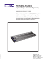
Thank you for choosing the Keencut FUTURA FLEXO Every effort
has been made to bring you a precision engineered product
with the promise of many years of valuable service. In order to
obtain maximum benefit from your machine please read these
instructions carefully. For advice and assistance or replacement
parts please contact your distributor or Keencut Ltd.
KC-FF 7272-03/13
MyBinding.com
5500 NE Moore Court
Hillsboro, OR 97124
Toll Free: 1-800-944-4573
Local: 503-640-5920

2 Identification
2.1 Know your FUTURA FLEXO
3 Operation
3.1 The Blade Cartridges
3.2 General Purpose Cutting 1
3.3 General Purpose Cutting 2
4 Maintenance
4.1 Squaring
4.2 Maintenance/Cleaning and Lubrication
5 Optional accessories
5.1 Cutting Fence Attachment
5.21 75cm Cutting Fence Kit - Alignment
5.22 75cm Cutting Fence Kit - Calibration
5.3 Base Extension Arms
5.41 Squaring Arm
5.42 Calibration ofthe Squaring Arm Measuring Scale
5.5 Lift & Hold
6 Specialist Uses
6.1 Cutting Flexo Plates
1
Contents
1
MyBinding.com
5500 NE Moore Court
Hillsboro, OR 97124
Toll Free: 1-800-944-4573
Local: 503-640-5920

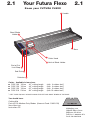
Know your FUTURA FLEXO
5
Handle
1
Base
4
Vertical Blade Holder
2
Cutter Head
Cutterbar
8
End Plate
7
End of Cut
Limit Stop 6
2.1
Your Futura Flexo
2.1
Bevel Blade
Holder
3
Cutter - Available in four sizes:
n FLEX 100 100cm 40” cutting length (with 6 rubber feet*)
n FLEX 120 120cm 48” cutting length (with 6 rubber feet*)
n FLEX 150 150cm 62” cutting length (with 8 rubber feet*)
n FLEX 218 218cm 86” cutting length (with 10 rubber feet*)
*
FEET TO BE EQUALLY SPACED ALONG THE LEFT AND RIGHT EDGES OF THE BASE.
You should have:
Cutting Mat
Pack of 100 Medium Duty Blades (Keencut Code CA50-019)
3mm Allen key
Instruction CD
MyBinding.com
5500 NE Moore Court
Hillsboro, OR 97124
Toll Free: 1-800-944-4573
Local: 503-640-5920

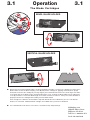
n Both the bevel and vertical blade holders are fitted with Blade Cartridges, to release the cartridge from either of the
blade holders slacken the blade clamping screw (B) and pull the cartridge out, gripping the black plastic pin (A).
The blade is held onto the cartridge by a str
ong magnet, place the blade between the two raised edges and slide it
so the back edge of the blade touches the depth adjustment screw. To adjust the blade depth turn the adjustment
screw (C) clockwise to extend the blade length and counter-clockwise to reduce it. Always check that the blade is
properly located in the cartridge befor
e loading it into the blade holder.
Each cartridge has a different coloured label to help with identification and calibration if pre-set to suit different
thicknesses of material. Additional blade cartridges are available from your Keencut distributor.
n The standard blade used with the Futura Flexo is the Medium Duty Utility blade (D).
The Blade Cartridges
3.1
Operation
3.1
BEVEL BLADE HOLDER
VERTICAL BLADE HOLDER
A
B
C
C
D
MyBinding.com
5500 NE Moore Court
Hillsboro, OR 97124
Toll Free: 1-800-944-4573
Local: 503-640-5920

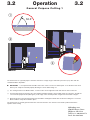
The Futura Flexo is a general purpose machine that will cut a large range of materials up to 6mm (1/4”) thick with the
standard medium duty blade.
n IMPORTANT: It is important that the table surface the cutter is used on is relatively flat. If not the base and cutter
bar may not clamp the material pr
operly allowing it to move whilst being cut.
1 The cutting head has two blade holders, a vertical cutter on the right hand side and a bevel cutter on the left.
2 To load material into the machine raise the long black handle and place the material under the cutter bar. Should the
cut need to be perpendicular (90 degrees) to the edge of the material position it against the End Plate to align it.
3 Alternatively place the material forward of the End Plate and align the blade with the desired cutting line. Lower the
black handle to clamp the material in place.
The Futura Flexo is normally operated from the end of the machine such that the cutter head is pulled towards the
operator when cutting,
General Purpose Cutting 1
3.2
Operation
3.2
à
à
1
2
3
52.5°
MyBinding.com
5500 NE Moore Court
Hillsboro, OR 97124
Toll Free: 1-800-944-4573
Local: 503-640-5920

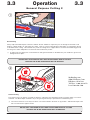
General Purpose Cutting 2
Bevel Cutting
Always adjust the blade depth so that the smallest amount of blade is exposed to just cut through the material, it will
produce a better quality cut and require less effort. There is a groove along the base plate which accommodates the tip
of the blade when cutting. Thin materials may need the cutting mat to support them to avoid the material being pressed
into the groove which will produce inconsistent and unsatisfactory results.
1 A cutting mat must always be used when bevel cutting thick materials as the blade may run outside the groove and
damage the base plate.
DO NOT REST YOUR HAND ON THE LONG LIFTING HANDLE WHILST CUTTING
BECAUSE THE BLADE PENETRATION WILL BE REDUCED.
V
ertical Cutting
The vertical cutter can also be used with or without a cutting mat, this will help to produce a better quality cut on most
materials. The blade depth should be set just long enough for the tip to penetrate the material being cut.
2 The vertical cutter has a two way lock which can lock the blade in the down or up position. Slide the black pin to the
left to lock and to the right to release.
DO NOT REST YOUR HAND ON THE LONG LIFTING HANDLE WHILST CUTTING
BECAUSE THE BLADE PENETRATION WILL BE REDUCED.
2
1
3.3
Operation
3.3
MyBinding.com
5500 NE Moore Court
Hillsboro, OR 97124
Toll Free: 1-800-944-4573
Local: 503-640-5920

à
à
à
à
à
4
12 3
5
6
à
Adjust with 5mm
Hexagon wrench
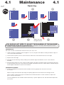
Squaring
top
bottom
à
4.1 Maintenance 4.1
n SQUARING THE CUTTER BAR TO THE END PLATE is carried out in our factory before despatch of all new
machines. Therefore adjustment should never be necessary.
SQUARING TEST
Take a piece of thick card or board at least 65 x 65cm (25 x 25”) in size.
1 Clamp it under the Cutterbar and trim off approx 1cm (1/2”) using the vertical blade, ensuring the bottom edge is in
close contact with the End Plate.
2 T
ur
n the boar
d a quarter of a tur
n counter-clockwise and trim the same amount from the second edge.
3 Repeat for the third edge.
4 And again for the fourth edge, always making sure the bottom edge of the Board is in close contact with the
End Plate.
5 Rotate the Mat a quarter of a turn counter-clockwise but this time place the bottom edge on the End Plate and slide
it to the left until it comes into contact with the Cutterbar
. If the board comes into contact with the Cutterbar along its
whole length the End Plate is square to the Cutterbar.
SQUARING ADJUSTMENT
6 If there is a gap between the board and the Cutterbar, then this gap represents four times the error of
the machine.
Adjust the angle of the End Plate by turning the Squaring Adjustment Screw with the 5mm hexagon wrench.
Turn it clockwise to adjust if the gap is at the bottom of the board and turn it counter-clockwise to adjust if the
gap is at the top of the board.
Close the gap between the Cutterbar and the End Plate by a quarter
. Repeat the test and make further adjustments
if necessary.
YOU SHOULD NOT NEED TO ADJUST THE SQUARING OF THE MACHINE!
Y
ou will
need
5mm
Cut
Cut
Cut
Cut
4

n MAINTENANCE
Your cutter is a precision made machine and will give many years of accurate and reliable service if you follow
these few simple steps.
Keep all liquids ( including tea and coffee) away fr
om the machine - spillages spoil the machines performance and
materials cut upon it.
Dust/vacuum daily, for stubborn stains use detergent/ water mix firstly applied to a cloth.
Cover the machine overnight with a plastic or fabric sheet.
If you need to move the machine away from the bench when it is not in use, store it either flat or if you have to stand
it on end fasten the end of cut stop and use a strong elastic band to fix the cutter head to it. Then stand it on its top
end leaning against a stable support.
Please note:- Standing the cutter on end should be avoided if possible but, providing it is done carefully no harm
will come to it.
In the event of heavy soiling on any part of the machine solvents can be used for cleaning but:-
Apply the solvent to a cloth and not directly on the cutter.
Read and comply with the solvents safety instructions.
Do not allow solvent to come in contact with any printed or plastic parts of the machine.
n CLEANING AND LUBRICATION OF THE CUTTER BAR
As above, clean the two guide bars using solvent on a cloth being careful not to get solvent on the measuring scale.
Lubricate using petr
oleum jelly or a firm grease, again apply it to a cloth then wipe it along the guide bars. Do not
apply too much grease a thin smear is all that is required.
Oil can be used lightly on the lift and hold, pivot lift arm hinges and cutter bar pivots.
4.2
Maintenance
4.2
MyBinding.com
5500 NE Moore Court
Hillsboro, OR 97124
Toll Free: 1-800-944-4573
Local: 503-640-5920

5.1
Optional Accessories
5.1
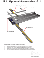
There are a number of accessories available for the Futura Flexo:
5.2 Cutting Fence Attachment - For accurate repeat cutting from 0 to 75cm (30”) wide
5.3
Base Extension Arms - Provide support for material bigger than the machine base.
5.4 Squaring Arm - For precise square cutting and with integral stop for pre-set measurements
5.5 Lift & Hold - For quick lift and hold of the cutter bar to enable two handed material positioning.
5.5 Lift and hold
5.4 Squaring Arm
5.3 Base Extension Arms
5.2 Cutting Fence Attachment
MyBinding.com
5500 NE Moore Court
Hillsboro, OR 97124
Toll Free: 1-800-944-4573
Local: 503-640-5920

75mm Cutting Fence Kit - Alignment
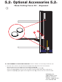
n THE ALIGNMENT OF THE CUTTING FENCE T-Bar with the Cutterbar is checked using two identical coins.
1 Place the coins as shown, one near the top of the Margin Guide T-Bar and the other near the bottom.
Move the T-Bar across to touch both coins and clamp the wingbolt (C).
If both coins do not touch the T
-Bar loosen the two Alignment Adjustment Screws (A).
Release the wingbolt (C) and move the T-Bar to the right touching the Margin Guide T-Bar on both spacers.
Tighten the wingbolt (C), gently tighten the two Alignment Screws (A), check the coins now contact the T-Bar.
1
5.21
Optional Accessories
5.21
A
C
MyBinding.com
5500 NE Moore Court
Hillsboro, OR 97124
Toll Free: 1-800-944-4573
Local: 503-640-5920

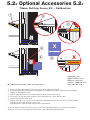
75mm Cutting Fence Kit - Calibration
n Calibrate the measuring scale to the vertical cutter:
1 Position the T-Bar approximately half way across the Base, tighten the wingbolt.
2 Ensure the blue metal scale adjacent to the wingbolt is set approximately to the mid-way point by turning the
adjacent small black plastic knob.
3 Make a small pencil mark on the aluminium adjacent to the position of the cursor.
4 Place a piece of stiff card on the machine so its left hand edge is in contact with the T-Bar.
5 Cut the card with the vertical cutter.
6 Measure the width of the cut, remove the T-Bar from the Slideway and stick the scale to it so the pencil mark is
aligned to the measured dimension on the scale.
Fine adjustment can then be made using the micro-stop adjuster.
Should a parallel cut need to be made to the bevel cutter just add approximately 6.5cm (2 9/16”) to the desired
dimension. A more accurate adjustment measurement can be obtained by experimentation.
5.22
Optional Accessories
5.22
1
2
3
6
5
4
à
X
X
MyBinding.com
5500 NE Moore Court
Hillsboro, OR 97124
Toll Free: 1-800-944-4573
Local: 503-640-5920

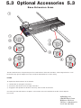
Base Extension Arms
The Base Extension Arms are packed in pairs and can be fitted to either side of the Base. When large boards are cut on
the machine they give the support necessary to keep the material flat for accurate cutting.
FITTING
To clip the Base Extension Arms to the machine:
1 Hold the Arm at 45 degrees to the Base.
2 Present the Arm into the slot in the edge of the Base.
3 Engage the Arm upwards into the Base slot and 4 lower the Arm to horizontal.
Check they are level with the base, the plastic screw and lock nut on the underside of the Arm can be adjusted
if necessary.
1
5.3
Optional Accessories
5.3
1
2
3
4
4
1
2
3
MyBinding.com
5500 NE Moore Court
Hillsboro, OR 97124
Toll Free: 1-800-944-4573
Local: 503-640-5920

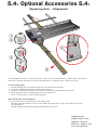
Squaring Arm - Alignment
The Squaring Arm is used to cut materials precisely square and to a pre-determined size. Before fitting, check that the
End Plate is square by carrying out the test on the 'Maintenance – Squaring' page 4.1, adjust if necessary
To fit the Squaring Arm
1 Hold the Squaring Arm at 45 degrees to the Base and forward of the End Plate.
2 Present the Squaring Arm into the slot in the edge of the Base.
3 Engage the Squaring Arm upwards into the Base slot and lower the Squaring Arm to horizontal.
4 Lift the right hand end of the Squaring Arm and slide it towards you.
Reverse the instructions to remove the Squaring Arm.
Align Squaring Arm with the End Plate
5 Loosen the two nuts on the underside of the Squaring Arm.
Raise the Cutter Bar and place a long accurate straight edge along the two edges of the End Plate and onto
the Squaring Arm.
Hold the Squaring Arm in position whilst gently tightening the two nuts.
5.41
Optional Accessories
5.41
4
3
1
2
à
5
MyBinding.com
5500 NE Moore Court
Hillsboro, OR 97124
Toll Free: 1-800-944-4573
Local: 503-640-5920

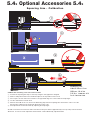
Squaring Arm - Calibration
Calibrate the measuring scale to the vertical cutter
1 Position the Squaring Arm Stop a short way along the arm, tighten the wingbolt.
2 Make a small pencil mark on the aluminium adjacent to the position of the cursor.
3 Place a piece of stiff card on the machine so its right hand edge is in contact with the Stop Finger.
4 Cut the card with the vertical cutter.
5 Measure the width of the cut, remove the Measuring Stop from the Squaring Arm and stick the scale to it so the
pencil mark is aligned to the measured dimension on the scale.
6 Fine adjustment can then be made by adjusting the Stop Finger.
Should a measured cut need to be made to the bevel cutter just subtract approximately 6.5cm (2 9/16”) from the desired
dimension. A more accurate adjustment measurement can be obtained by experimentation.
5.42
Optional Accessories
5.42
1
6
5
4
à
à
à
3
X
X
2
MyBinding.com
5500 NE Moore Court
Hillsboro, OR 97124
Toll Free: 1-800-944-4573
Local: 503-640-5920

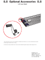
Lift and Hold
The Lift and Hold is used to raise and hold the Cutterbar above the base so you can have both hands free when
positioning the material ready for cutting.
Position the Lift and Hold and fit the screw into the threaded hole, tighten using the 4mm hexagon wrench.
5.5
Optional Accessories
5.5
MyBinding.com
5500 NE Moore Court
Hillsboro, OR 97124
Toll Free: 1-800-944-4573
Local: 503-640-5920

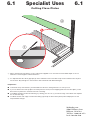
Cutting Flexo Plates
6.1
Specialist Uses
6.1
1 When cutting Flexo Plate always use the cutting mat supplied to cut onto and ensure the blade depth is set to a
minimum to cut through the material thickness.
2 It is important that the silicon grip tape (A) on the underside of the cutter bar is kept clean to hold the flexo in place.
If it becomes dirty through use clean it with a cloth moistened with diluted detergent.
Helpful hints:
n To eliminate entry and exit burrs, push the blade into the flexo, through the base, to start your cut.
n If you cut with the base side up place the foam protector sheet (used for shipping between each flexo plate), on the
base boar
d, to protect the emulsion side from scratching.
n To stabilize the plate for ultra-fine trimming, try starting your cut 2cm (1”) in from the edge. Come back and complete
the cut fr
om the edge.
n To obtain smooth clean edges and avoid fracturing (especially on thicker flexo plates) make multiple passes and
fr
equent blade changes.
A
1
2
MyBinding.com
5500 NE Moore Court
Hillsboro, OR 97124
Toll Free: 1-800-944-4573
Local: 503-640-5920
-
 1
1
-
 2
2
-
 3
3
-
 4
4
-
 5
5
-
 6
6
-
 7
7
-
 8
8
-
 9
9
-
 10
10
-
 11
11
-
 12
12
-
 13
13
-
 14
14
-
 15
15
-
 16
16
-
 17
17


