Logan Graphic Products 655 Le manuel du propriétaire
- Taper
- Le manuel du propriétaire

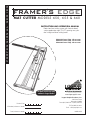
FRAMER'S EDGE
MAT CUTTER MODELS 650, 655 & 660
www.logangraphic.com
Purchase Date
ID Number (on bottom of board)
Date (on bottom of board)
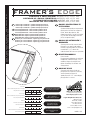
INSTRUCTION AND OPERATION MANUAL
Professional mat cutting system with laminate board
surface, production stops, 9" & 27" squaring arms, plus
dual straight and bevel cutting heads
PROFESSIONAL SERIES
For best results use only
authentic Logan blades
Logan Graphic Products, Inc.
1100 Brown Street
Wauconda, IL 60084
Phone (847) 526-5515 Fax (847) 526-5155
Toll Free (800) 331-6232
L618N3 6/05
Email - [email protected]
Model 650 Framer’s Edge - 40" mat cutter
Model 655 Framer’s Edge - 48" mat cutter
Model 660 Framer’s Edge - 60" mat cutter

Logan Graphic Products Inc., 1100 Brown Street, Wauconda, IL 60084 Toll Free 1 800 331 6232 www.logangraphic.com
1
FRAMER'S EDGE
MAT CUTTER MODELS 650, 655 & 660
The Logan Framer’s Edge Mat
Cutter has been designed
specifically with the framer in
mind. All the materials are heavy-
duty to withstand the rigors of
professional mat cutting and to
provide the accuracy framers
demand.
Features which Logan introduced
to the industry years ago like the
squaring arm, mat guide, the
movable production stop and the
high-tech aluminum cutting bar
have all been re-designed for
reduced fatigue, simple blade
change and precise adjustment of
the blade to maintain straight cuts
with no overcuts. In addition, the
cutting head contains a new
gauge which eliminates overcuts.
We are confident that the quality,
accuracy and dependability of the
Framer’s Edge will be everything
you expect in a professional mat
cutter.
This instructional manual is
written to acquaint you thoroughly
with this product. Referred to at
the outset, it will answer many
questions that may arise during
use. You will find that the time
taken will be well worth it and you
will be cutting top quality mats in
no time.
NOTE*
This instruction manual covers
the set-up and operation
instructions for the following
Framer’s Edge models:
#650 40” mat cutter
#655 48” mat cutter
#660 60” mat cutter
INTRODUCTION: TABLE OF CONTENTS:
Warranty
Logan Graphic Products, Inc. (“Logan”) warrants the 650/655/660 Framer’s Edge to be free from defects in parts and
workmanship for a period of two years from the date of original purchase. Logan warrants that it will either repair
or replace, in its sole discretion, any necessary replacement parts found to be defective. Should the product need to
be returned to Logan for repair or replacement parts, authorization for any return must come from Logan. Costs of
returning the product to Logan, including insurances, shall be borne by the purchaser. Logan shall not be liable for
any damages or losses, incidental or consequential, direct or indirect, arising from the use of this product. This
warranty extends only to the original purchaser and is not assignable or transferable. This warranty is in lieu of all
other warranties, expressed or implied.
Getting to know your Framer’s Edge Mat Cutter and identification of machine components
Set-up and Orientation
A. Unpacking 4
B. Work surface and orientation 4
C. Installing the mat guide channels 4
D. Attaching the squaring arms 4
E. Installing the mat guide 5
F. Blade installation-bevel cutter 5
G. Blade installation-straight cutter 5
H. Attaching the movable stop 6
I. Use a backing sheet 6
How to Cut a Mat
A. Straight cutting a mat board to size 7
B. Cutting a beveled opening using marked lines 8
C. Cutting a beveled opening using production stops 9
Adjustments & Maintenance
A. Blade depth adjustment-bevel cutter 10
B. Blade depth adjustment to cut 8-ply matboard 10
C. Blade tip adjustment 10
D. Overcut adjustment screws 11
E. Blade depth adjustment-straight cutter 11
F. Re-square the squaring arm 12
G. Re-parallel the mat guide 13
H. Bearing removal & replacement 13/14
Creative Matting Guide
A. Double Mat 15
B. Offset Corner Mat 15
C. Inlay Mat 15
Parts List and Exploded View Drawings
A. Cutting board 16
B. Cutting head 17
Trouble Shooting 18

Logan Graphic Products Inc., 1100 Brown Street, Wauconda, IL 60084 Toll Free 1 800 331 6232 www.logangraphic.com
2
FRAMER'S EDGE
MAT CUTTER MODELS 650, 655 & 660
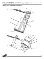
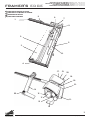
1. Squaring Arm
Right angle back stop necessary to hold material square to Cutting Bar.
2. Cutting Bar
Heavy-duty extruded Cutting Bar with teflon coating and polished
surface.
3. Cutting Board
3/4” thick laminate surface Cutting Board.
4.Top Support Arm
Heavy-duty hinged aluminum arm provides support for Cutting Bar and
Handle Bar.
5. Handle Bar
Square shaped handle used to raise Cutting Bar to vertical position.
6. Bottom Production Stop
Production Stop tightens to the Cutting Bar Rod and stops the cutting
head at the location determined by the scale setting.
7. Bottom Support Arm
Heavy-duty hinged aluminum arm provides support for Cutting Bar and
Handle Bar.
8. Cutting Bar Scale
With dual inch/metric scale recessed into cutting bar to be used
together with the bottom production stop.
9. Squaring Arm Stop
Aluminum stop that slides onto either end of the Squaring A rm and
tightens into position.
10. Mat Guide
Movable, parallel guide bar used to set border width of the mat being
cut.
11. Cutting Head
Mounting block that glides on cutting bar and contains both bevel and
straight cutting blade holders.
12. Bevel Cutter Holder
45 Degree Bevel Blade Holder.
13. Straight Cut Blade Holder
90 Degree straight cut blade holder with lock-down pin.
14. Movable Production Stop
Movable stop which connects to cutting head. Allows fast production
cutting of mat board.
15. 8-Ply Setting
Adjustment screw used to set bevel cutting head to cut 8-ply thickness
matboard. Only the #268 blade will cut effectively at this setting.
16. Indicator Plate
Metal outrigger with green and red dot used to accurately start and
stop on marked lines resulting in minimal overcuts.
17. Blade Holding Screw
Easy grip blade screw for tightening blade on both straight and bevel
blade holders.
18. Bevel Cutter Blade Depth Adjustment
For adjusting the depth of the blade on the bevel side of the cutting
head.
19. Straight Cutter Blade Depth Adjustment
For adjusting the depth of the blade on the straight side of the cutting
head.
20. Lock-Down Pin
Pin for locking Straight Cutting Blade Holder in a down position so that
no downward pressure is needed when straight cutting.
21. Bottom Overcut Adjustment
For adjusting overcut at the bottom of the mat.
22.Top Overcut Adjustment
For adjusting overcut at the top of the mat.
23. Blades (Fig. 1, pg. 5)
#269 double bevel blade used for cutting standard thickness matboard.
#268 single bevel blade used for cutting 8-ply double thick matboard.

Logan Graphic Products Inc., 1100 Brown Street, Wauconda, IL 60084 Toll Free 1 800 331 6232 www.logangraphic.com
3
FRAMER'S EDGE
MAT CUTTER MODELS 650, 655 & 660
1.
2.
3.
4.
5.
6. 7.
8.
9.
10.
11.
12
13.
14
15
16
17.
17
21.
19.
20.
22.
18.
IDENTIFICATION OF MACHINE COMPONENTS

Logan Graphic Products Inc., 1100 Brown Street, Wauconda, IL 60084 Toll Free 1 800 331 6232 www.logangraphic.com
4
FRAMER'S EDGE
MAT CUTTER MODELS 650, 655 & 660
SET-UP AND ORIENTATION
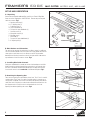
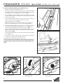
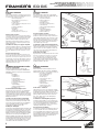
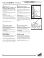
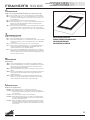
A. Unpacking
Remove the corrugated cardboard fillers and lift your Framer’s Edge Mat
Cutter out of the shipping box. SAVE THE BOX. Remove the parts bag and
check the contents: Fig 1
a. Squaring Arm Stop (1)
b. 27" Squaring Arm (1)
c. Production Stop (1)
d. Logan Screwdriver (1)
e. Five pack of Logan 269 blades (2)
f. Channel screws (4)
g. Mat guide channels (2)
h. Movable stop (1)
i. Mat Guide (1)
j. Five pack of Logan #268 blades (1)
k. 9" Squaring Arm (1)
B.Work Surface and Orientation
The work surface must be flat and smooth. Any dips or warps in a table top
can cause the base board of the mat cutter to also warp. Never lean the mat
cutter against a wall when not in use. Always store flat.The procedure
detailed in the following instructions refer to the right and left side and the
top and bottom of the mat cutter as shown. Fig 2
C. Installing Mat Guide Channels
Putting the rounded end in towards the center of the board press each Mat
Guide channel into the base board lining up the holes in the channels with
the holes in the board. Stand the base board up on its edge and insert the
four channel screws from the underside of the board and tighten. Fig 3
D. Attaching the Squaring Arm
There are two squaring arms provided to choose from. The 27" arm is used for
straight cutting. The 9" arm is an option if straight cutting is unnecessary or
saving space is required. The screws for attaching the Squaring Arm and the
small metal tool for aligning it can be found screwed into the board slot. Use
the alignment tool to line up the slot in the board with the slot in the
Squaring Arm before tightening the screws. Fig 4
a.
b.
c.
d.
e.
#269
#268
f.
g.
h.
i.
j.
k.
Fig 1
Fig 4
Fig 3
Fig 2 Top
Right
Left
Bottom

Logan Graphic Products Inc., 1100 Brown Street, Wauconda, IL 60084 Toll Free 1 800 331 6232 www.logangraphic.com
5
FRAMER'S EDGE
MAT CUTTER MODELS 650, 655 & 660
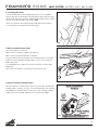
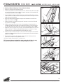
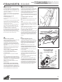
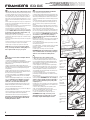
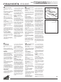
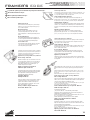
F. Blade Installation-Bevel Cutter
There are two blades to choose from:
#268 is used for cutting 8-ply or double thick matboard.
#269 is used for cutting standard thickness matboard.
Using the handle bar, lift the cutting bar to the full upright position. Loosen blade
holding screw and insert blade into blade holder as far as it will go. Tighten the
blade holding screw.
To use #268 blade, refer to page 10 for instructions. Machine is preset to #269
blade setting.
NOTE: The hole in the blade is not designed to line up with the screw.
G. Blade Installation-Straight Cutter
With the handle bar in the down position, pull out on the lock down pin and rotate
the blade holder as far back as it will go. Loosen the blade holding screw and slide
one 269 blade into the blade holder as far back as it will go. Re-tighten the blade
holding screw. Rotate the blade holder back to the neutral position. Fig 7
E. Installing Mat Guide
To install the Mat Guide, loosen the knobs three full turns. Do not completelty
remove knobs. With the raised edge of the Mat Guide facing the Cutting Bar, align
the Mat Guide slides with the channels and drop the Mat Guide into place. Tighten
the knobs to set the Mat Guide at any increment. Fig 5
NOTE: If you experience any trouble dropping the Mat guide into the channels,
loosen the knobs one more additional turn and try again.
Fig 5
Fig 6
Fig 7

Logan Graphic Products Inc., 1100 Brown Street, Wauconda, IL 60084 Toll Free 1 800 331 6232 www.logangraphic.com
6
FRAMER'S EDGE
MAT CUTTER MODELS 650, 655 & 660
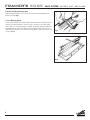
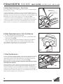
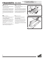
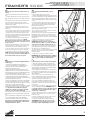
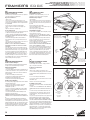
I. Use a Backing Sheet
For best results ALWAYS use a Backing Sheet when bevel cutting. A Backing Sheet is a
scrap piece of mat board which is at least as long as the mat you are cutting and at
least 4” wide. Your first Backing Sheet is included. The Backing Sheet will need to be
changed periodically. Helpful Hint: Move the Backing Sheet slightly after each cut to
avoid cutting into previous scores that may cause the blade to flare out causing a curve
in your cut. Fig 9
H. Attach the Movable Stop Arm
Slide the Movable Stop Arm onto scale bar with the leg toward board bottom and
tighten in position. Fig 8
Fig 8
Fig 9

FRAMER'S EDGE
MAT CUTTER MODELS 650, 655 & 660
Logan Graphic Products Inc., 1100 Brown Street, Wauconda, IL 60084 Toll Free 1 800 331 6232 www.logangraphic.com
7
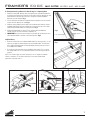
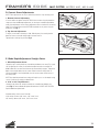
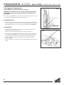
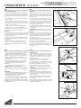
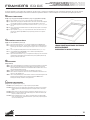
A. Straight Cutting a Board to Size Using 27" Squaring Arm
1. Remove the mat guide, backing sheet, the squaring arm stop and the production
stop. Attach the squaring arm stop onto the far right end of the squaring arm and
slide inward until the left side of the stop is along the increment needed to
downsize your mat board to. Fig 1
2. Lift the cutting bar and slide the mat board along the squaring arm until it makes
contact with the squaring arm stop. Fig 2
3. Slide the cutting head past the far end of the mat board and rotate the straight
cut blade holder down until the lock down pin snaps over the top of the cutting
head locking the blade holder into cutting position. Fig 3
4. Holding the blade holder as shown in Fig 4, pull the cutting head directly
towards yourself until the mat board is completely cut.
5. IMPORTANT After finishing the cut make sure you pull the lock-down pin out to
allow the blade holder to go back to the neutral position. Fig 5
Helpful Hints:
1. After the lock down pin has locked the blade holder into cutting position, it is not
necessary to apply any downward pressure on the blade holder. The lock down
pin is holding the blade holder at the proper depth and extra pressure causes it
to cut deeper than needed.
2. Do not put any pressure down on the handle bar when cutting. This can cause
the cutting head to lift off of the mat board and not cut all the way through the
material.
NOTE: Your Framer’s Edge mat cutter has been pre-set to straight cut standard
thickness mat board. To cut thicker material you must make a blade depth
adjustment. See page 10 & 11.
Fig 1
Fig 2
Fig 3 Fig 4 Fig 5

Logan Graphic Products Inc., 1100 Brown Street, Wauconda, IL 60084 Toll Free 1 800 331 6232 www.logangraphic.com
8
FRAMER'S EDGE
MAT CUTTER MODELS 650, 655 & 660
Fig 1
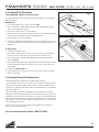
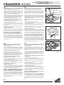
B. Cutting a Beveled Opening Using Marked Lines
1. Always use a backing sheet when bevel cutting.
2. To release mat guide loosen the black knobs two turns. Slide the mat guide in
the angled slots until the front edge of the mat guide is along the increment of
the mat guide scale of the border width you wish to cut. Fig 1
3. Lift the handle bar and place a backing sheet on the cutting board. Then place
your pre-sized mat board color side down against the squaring arm and to the
left against the mat guide.
4. Lower the handle bar. With a pencil draw a line on the back of the mat board
using the left side of the cutting bar as a guide. Do this for the
remaining three sides of the mat. Fig 2
5. Slide the cutting head into position so that the edge of the metal near the
green dot on the indicator plate is directly over the marked line. Fig 3
6. Rotate the bevel blade holder down completely to seat the blade into the mat.
TIP: Hold the cutting head firmly enough to not allow it to “creep forward”
when first inserting the blade which will produce an overcut. Fig 4
Maintaining downward pressure, pull the cutting head towards yourself until
edge of the metal near the red dot on the indicator plate is directly over the
bottom marked line. Fig 5
7. Rotate the bevel blade holder up to the neutral position and lift the handle bar
to an upright position.
8. Turn the mat 1/4 turn to the right and make sure that the mat is down against
the squaring arm and against the mat guide on the left.
9. Continue steps 5 through 8 until all four sides are cut.
TIP: Do not push down on the handle bar when cutting, this will flex the
cutting bar upwards and prevent the blade from cutting through the mat
board.
Fig 2
Fig 3 Fig 4 Fig 5
Start on green dot. Stop on red dot.
Rotate blade holder.

FRAMER'S EDGE
MAT CUTTER MODELS 650, 655 & 660
Logan Graphic Products Inc., 1100 Brown Street, Wauconda, IL 60084 Toll Free 1 800 331 6232 www.logangraphic.com
9
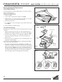
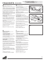
C. Cutting a Beveled Opening Using Production Stops
1. Always use a backing sheet when bevel cutting.
2. To release mat guide loosen the black knobs two turns. Slide the mat guide in the angled
slots until the front edge of the mat guide is along the increment of the mat guide scale
of the border width you wish to cut. Fig 1
3. Lift the handle bar and place a backing sheet on the cutting board. Then place your pre-
sized mat board color side down against the squaring arm and to the left against the mat
guide and lower the handle bar.
4. Attach and slide the bottom production stop up to the increment on the scale of the
border size you wish to cut. Fig 2
5. Slide the top edge of the movable stop up to the increment on the scale of the border
size you wish to cut. Fig 3
6. Slide the cutting head into position in front of the top edge of the mat board. As the
movable stop approaches the edge of the mat board, press down on the stop foot with
your left index finger until it gently makes contact with the top edge of the mat. Fig 4
7. Holding the stop foot in place with your finger, rotate the blade holder down to enter the
blade into the mat. TIP: Hold the cutting head firmly enough to not allow it to “creep
forward” when first inserting the blade which will produce an overcut.
8. Release the stop foot with your finger so that it raises above the edge of the mat board
and pull the cutting head towards yourself until it makes gentle contact with the bottom
production stop. Fig 5
9. Turn the mat 1/4 turn to the right and make sure that the mat is down against the
squaring arm and against the mat guide on the left.
10. Continue steps 6 through 9 until all four sides are cut.
TIP: Do not push down on the handle bar when cutting, this will flex the cutting
bar upwards and prevent the blade from cutting through the mat board.
Fig 1
Fig 2
Fig 3
Fig 4
Fig 5

Logan Graphic Products Inc., 1100 Brown Street, Wauconda, IL 60084 Toll Free 1 800 331 6232 www.logangraphic.com
10
FRAMER'S EDGE
MAT CUTTER MODELS 650, 655 & 660
A. Blade Depth Adjustment - Bevel Cutter
NOTE: The depth setting of your Framer’s Edge is pre-set to cut U.S. Standard thickness
mat board. (.055” or 2.2mm)
To adjust the blade depth on the bevel cut, use the screwdriver provided and turn the
screwdriver in the slotted screw on the cutting head as shown. To decrease depth of the
bevel blade, turn the screw clockwise into the cutting head. To increase the depth of the
bevel blade, turn the screw counter-clockwise out of the cutting head. Fig 1
It is always ideal to have just enough blade depth to slice through the mat you are
cutting and score slightly into the backing sheet. Extra blade depth can allow the blade
to flex resulting in hooks or curves in the cut. Extra blade depth can also cause the
blade to start its cut sooner and stop its cut later than needed resulting in overcuts.
B. Blade Depth Adjustment to Cut 8-Ply Matboard
1. First remove the blade from the bevel blade holder.
2. Using the screwdriver supplied, tighten the small screw on the bevel blade holder
marked "8-ply setting".(Fig A)
3. Insert Logan 268 8-Ply Blade. Notice the blade has a bevel on only one edge. Be
careful to insert blade so bevel shows. Re-tighten the blade holding screw.
Note: #268 blade can only be used on one corner, bevel edge showing. It will not
operate properly installed with the opposite edge showing.
Fig 1
Fig A
Straight Depth
Adjustment Screw
Bevel Edge Depth
Adjustment Screw
C. Blade Tip Adjustment
If curves in your bevel cut become a problem, it may warrant an adjustment to the blade
tip. At the end of the bevel blade holder nearest the tip of the blade you will find a
small blade tip adjustment screw. When adjusted this screw will put more pressure
against the blade tip causing it to ride closer to the cutting bar. (Fig 2)
Do not turn this screw until you inspect the position of the blade tip in relation
to the edge of the cutting bar.
Ideally, the blade tip should just glide against the edge of the bar when activated. Raise
the handle bar and inspect this relationship by pivoting the blade holder down and
watching the blade tip as it passes by the edge of the cutting bar. If the blade tip is just
touching it, do not adjust the screw. If there is too much or too little contact between
the blade tip and the cutting bar then adjust the screw accordingly. Make only slight 1/4
turns on the screw and do test cuts to ensure accuracy.
Fig 2

FRAMER'S EDGE
MAT CUTTER MODELS 650, 655 & 660
Logan Graphic Products Inc., 1100 Brown Street, Wauconda, IL 60084 Toll Free 1 800 331 6232 www.logangraphic.com
11
E. Blade Depth Adjustment Straight Cutter
1. Micro Adjustment Screw
Located on top of cutting head, use screw driver provided to turn screw (Fig 1, page
10). By adjusting this screw you will effect the depth at which the straight cut
blade holder locks into when the lock down pin automatically engages. To decrease
depth of the straight blade, turn the screw clockwise into the cutting head. To
increase the depth of the straight blade, turn the screw counter-clockwise out of
the cutting head.
NOTE: Any depth beyond maximum setting will require you to use the depth setting
screws located on the straight cut blade holder.
2. 3/16" or 3/8" Depth Screws
Located on the side of the straight cut head, use screwdriver provided to turn
screw (Fig. 5). Remove blade and tighten desired screw. DO NOT OVER-TIGHTEN.
Replace blade and tighten knob.
Standard setting = both screws loosened.
3/16" setting = bottom 3/16" screw , 3/8" screw loose.
3/8" setting = bottom 3/8" screw , 3/16" screw loose.
Fig 5
Fig 3
D. Overcut Screw Adjustments
NOTE: These adjustments are only for when the production stops are being used.
1. Bottom Overcut Adjustment
If over or under cuts appears at the BOTTOM of the cut when using the production
stops even after a blade depth adjustment, use the Logan screwdriver provided to
make slight adjustments on the overcut adjustment screw on the back of the cutting
head. This screw will fine tune the BOTTOM over/under cut only when using the
production stop. Fig. 3
2.Top Overcut Adjustment
To adjust, loosen knob to allow leg to slide. Slide leg away from cutting head to
decrease overcut or toward cutting head to increase overcut.
Tighten knob to lock leg into position. Fig. 4
Fig 4

Logan Graphic Products Inc., 1100 Brown Street, Wauconda, IL 60084 Toll Free 1 800 331 6232 www.logangraphic.com
12
FRAMER'S EDGE
MAT CUTTER MODELS 650, 655 & 660
F. Re-Square the Squaring Arm
TOOLS NEEDED: Screwdriver, Carpenter’s Square.
ATTENTION: It is common for 32” x 40:” sheets of mat board to be un-square
when bought. Take this into account before making any adjustments to the
Squaring Arm.
Before making any adjustments to the squaring arm, make sure that the machine is truly
out of square, not the matboard, by using the squareness test.
SQUARENESS TEST
1. Place the carpenter’s square against the right hand side of the cutting bar and down
against the squaring arm. Look to see if there are any gaps between the carpenter’s
square and the squaring arm. If so, the squaring arm needs to be adjusted. Fig 6
TO RE-SQUARE
1. By looking at where the gap is, you can determine which way the squaring arm
needs to go in order to be square again.
2. Remove the squaring arm and locate the three screws inside of the slot.
3. Adjust only two screws A&B, DO NOT ADJUST C. To adjust you must turn screws A
& B in equal but opposite directions. To move the far right end of the squaring arm
towards the top end of the machine, turn adjustment screw B outward (counter-
clockwise) about a quarter turn and adjustment screw A inward (clockwise) a
quarter turn. Fig 7
4. Re-install the squaring arm and check for square. Make additional adjustments until
square.
Fig 6
Place square here
Fig 7

FRAMER'S EDGE
MAT CUTTER MODELS 650, 655 & 660
Logan Graphic Products Inc., 1100 Brown Street, Wauconda, IL 60084 Toll Free 1 800 331 6232 www.logangraphic.com
13
G. Re-Parallel The Mat Guide
TOOLS NEEDED: Phillips Screwdriver, Ruler.
To re-parallel the Mat Guide, first determine that the Mat Guide is out of parallel by
doing a parallel test.
Parallel Test:
1. Lock the Mat Guide at the 2” mark on the scale. Fig. 8
2. Place a scrap piece of matboard under the Cutting Bar and up against the Mat
Guide at the top end of the machine.
3. Using a pencil, draw a line across the matboard.
4. Slide the mat all the way down to the bottom where you are standing keeping the
mat against the mat guide but not against the Squaring Arm.
5. Draw another line across the matboard.
6. The piece of matboard should now appear to only have one single line across it. If
the two lines drawn do not line up with each other, the Mat Guide needs to be re-
paralleled.
To Re-parallel:
1. Release the Mat Guide screws.
2. Use a Phillips head screwdriver to loosen the screws on either side of the black
knobs one turn each. There are four screws total to be loosened this way.
3. Place a metal ruler or suitable straight edge between the Mat Guide and the
Cutting Bar. Fig. 9
4. Slide the Mat Guide against the straight edge and the Guide Rail. Make sure both
the Mat Guide and the Guide Rail are making solid contact on both sides of the
straight edge.
5. Re-tighten the Black Knobs first.
6. Then re-tighten the four screws. Do another parallel test to ensure that the Mat
Guide is now parallel.
H. Bearing Removal & Replacement
Additional Requirements: 600 Grit Silicon Carbide Paper (supplied)
If you have tried to eliminate all other causes of hooks and curves and they still exist,
check the cutting head for wobble on the cutting bar. If significant wobble occurs, it
may be time for a bearing replacement. Keep in mind that bearings last around three
years with regular use.
The Framer’s Edge cutting head is designed to ride on Delrin bearings installed
between the cutting head and cutting bar. The Delrin absorbs the wear so that costly
replacement and constant oiling of metal parts is not necessary. Logan provides these
bearings free for the lifetime of your machine. They will be sent to you free of charge
upon request. If you feel you cannot replace the bearing yourself, you can arrange for
our service department to do it.
NOTE: You must call to get a Return Authorization Number before sending your
machine in for bearing replacement.
For Service Assistance Phone 1-800-331-6232
Straight Edge
2”
Fig 8
Fig 9

Logan Graphic Products Inc., 1100 Brown Street, Wauconda, IL 60084 Toll Free 1 800 331 6232 www.logangraphic.com
14
FRAMER'S EDGE
MAT CUTTER MODELS 650, 655 & 660
Bearing Removal & Replacement
To Install New Bearings
If the Cutting Head has sufficient wobble and the cut is hooking, the Delrin
bearings need replacement.
To Remove Old Bearings:
1. Remove the blades.
2. Loosen screws A & B from bottom support arms. Fig 10
3. Slide Cutting Bar as far into the hole in the TOP support arm as possible
and lift it out and away from the BOTTOM support arm.
4. Slide Cutting Head off bar.
5. Use a screwdriver to remove four bearing screws and the indicator plate
screw. Fig 11
6. Remove old bearings and indicator plate.
To install new bearings:
New bearings are molded slightly oversize and require fitting to the existing
cutting bar.
1. Replace the new bearings. BE SURE THE “FLATS” MOLDED INTO THE
BEARINGS FACE TOWARD THE CENTER OF THE CUTTING HEAD. Fig 11
2. Now place a piece of 600 grit silicon carbide paper (supplied) on a flat,
even surface and gently sand away a small amount of the exposed
bearing surface.
3. After removing some of the bearing surface, try the Cutting Head on the
Cutting Bar. It should fit tightly.
NOTE: THIS IS A TRIAL AND ERROR METHOD OF BEARING REPLACEMENT.
DO NOT OVER-SAND THE BEARINGS.
4. At this point, check the relationship of the blade tip to the edge of the
Cutting Bar. If the blade hits the Cutting Bar before it reaches the end of
the bar, then more bearing surface has to be removed from the STRAIGHT
SIDE of the bearings. Fig 12 On the contrary, if the blade DOES NOT hit
the edge of the Cutting Bar, then more bearing surface must be removed
from the BEVEL SIDE of the bearings so that ultimately the blade will
JUST hit the edge of the bar as the blade enters the matboard.
Fig 10
Fig 11
Indicator Plate
Indicator
Plate Screw
Remove
Bearing
Screws
Remove
Bearing
Screws
A
Too Far Correct Too Close
Fig 12
B

FRAMER'S EDGE
MAT CUTTER MODELS 650, 655 & 660
Logan Graphic Products Inc., 1100 Brown Street, Wauconda, IL 60084 Toll Free 1 800 331 6232 www.logangraphic.com
15
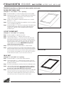
DOUBLE RECTANGLE MAT
(Example: 8” x 10” with 31/2”x 5
1/2” opening)
Step 1 Set the Mat Guide to 2” and cut an opening in the mat from the BACK.
Step 2 Keeping the fallout piece in place, run double sided tape around the back
of the window border. Do not put tape on cut line. Also put a small
swatch of tape in the center of the fallout.
Step 3 Straight cut a second piece of matboard of desired color to an outside
dimension 71/2” x 91/2”.
Step 4 Affix the second mat FACE DOWN to the taped back of the first mat being
sure it is centered reasonably well.
Step 5 Set the Mat Guide to 21/4” and cut the second opening. The double fallout
will drop from the window and the mat will be finished and perfectly
aligned. NOTE: Triple mats can be achieved by repeating the above
procedures again.
OFF-SET CORNER MAT
(Example: 8” x 10” with 7” x 5” opening)
Step 1 Set the mat guide at 2” and draw all four lines.
Step 2 Reset the Mat Guide at 11/2” and draw another set of lines.
Step 3 Leaving the Mat Guide at 11/2”, place the mat in the cutter, put on the
Bevel Cutting Head and line up the silver indicator line with the bottom
pencil line closest to center of the mat. Cut until the silver indicator lines
up with he top pencil line closest to the center of the mat. Using the
same procedure, cut all four sides. IMPORTANT: At this point the
fallout will not drop from the window.
Step 4 Remove the mat and reset the Mat Guide to 2”. Reinsert the mat.
Step 5 Line up the silver indicator line on the Bevel Cutting Head with the drawn
pencil line furthest from the center of the mat. Cut until the silver indicator
line lines up with the line at the top of the mat furthest from the center of
the mat. Using the same procedure, cut all four sides. NOTE: Be careful to
hold the fallout piece in place as you turn the mat for the last cut.
Double Mat
Off-Set Corner Mat
Inlay Mat
INLAY MAT
(Example: 8” x 10” with 7” x 5” opening)
Step 1 Set the Mat Guide at 2” and cut as per regular instructions.
Step 2 Reset the Mat Guide at 11/2”. Keeping the fallout in place, cut the mat
again as per regular instructions. You may keep the fallout piece in place
by taping it on the back.
Step 3 Discard the outer border piece and fallout. Retain the inside border cutout.
Step 4 Leaving the Mat Guide in place at 11/2”, cut a second mat of a different
color as per regular procedures. IMPORTANT: The second mat must
be of the exact same outside dimension as the first mat.
Step 5 Remove the fallout piece from the second mat and place the inside border
cutout from the first mat in the window opening from the second mat.
The two pieces should fit together like a puzzle creating a flush surface
across the front of the mat. Put tape on back to hold it in place.
Detailed instructions on how to cut more creative style mats.

Logan Graphic Products Inc., 1100 Brown Street, Wauconda, IL 60084 Toll Free 1 800 331 6232 www.logangraphic.com
16
FRAMER'S EDGE
MAT CUTTER MODELS 650, 655 & 660
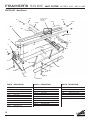
104-N cutting bar
106-7 squaring arm 27"
106-9 squaring arm 9"
107-2N1 squaring arm scale
109-N stop screw
112 mat guide knobs
112-F stop screw
113 support arm
116 shoulder bolt
118-N hinge block
120-N1 cutting bar stop
124-N board foot
134 squaring arm stop
135 handle bar
153-2 mat guide
203-N screw
211 handle bar screw
216 set screw
221 end cap
222 bumper
602-N mat guide slide
603-N mat guide wedge
604 mat guide screw
608-N1 cutting board
610-M mat guide scale
616 squaring arm screw
730-N cutting bar scale
1004 mat guide channel
1025-N mat guide channel screws
PART # DESCRIPTION PART # DESCRIPTION PART # DESCRIPTION
104-N
106-7
730-N
113
116 216
118-N
116
120-N1
134 112-F
602-N
603-N
112
1025-N
604
153-2
1004
211
124-N
135
221
610-M
107-2N1
109-N
113
see page 17 for
cutting head
schematic
222
203-N
608-N1
616
PARTS LIST - Base Board

Logan Graphic Products Inc., 1100 Brown Street, Wauconda, IL 60084 Toll Free 1 800 331 6232 www.logangraphic.com
17
FRAMER'S EDGE
MAT CUTTER MODELS 650, 655 & 660
PART # DESCRIPTION PART # DESCRIPTION
PART # DESCRIPTION
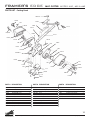
PARTS LIST - Cutting Head
L101-650 cutting head base 1
L102-A bevel blade holder 1
L102-B straight blade holder 1
L103-A bevel blade cover 1
L103-B straight blade cover 1
L108 shim 1
L111-N scale bar 1
L114-A2 shoulder screw 2
L115 Delrin bearing 2
L117-N movable stop arm 1
L139 gauge screw 1
L143-N indicator gauge 1
L146-N movable stop leg 1
L147-N lock-down pin 1
L202/204 post 1
L206-N blade tip screw 2
L207-N bearing screw 4
L208-N cover screw 1
L112-F stop screw 1
L220-N blade screw 2
L241-N scale bar screw 1
L242 e-ring 1
L273 blade cover screw 2
L430-A straight cut blade depth screw 3
L613 bevel return spring 1
L614 straight return spring 1
L730-N movable stop scale 1
L865-N bevel blade depth screw 1
L254-N overcut set screw 1
L101-650 N
L220-N
L1273
L208-N
L147-N
L220-N
L865-N
L112-F
L444-250
L146-N
730-N
L241-N
L430-A
L111-N
L117-N
L206-N
L273
L206-N
L273
L114-A2
L108
L102-B
L614
L202/204
L103-A
L114-A2
L108
L102-A
L613
L143-N
L207-N
L115
L115
L207-N
L242
L103-B
L139
L254-N

Logan Graphic Products Inc., 1100 Brown Street, Wauconda, IL 60084 Toll Free 1 800 331 6232 www.logangraphic.com
18
FRAMER'S EDGE
MAT CUTTER MODELS 650, 655 & 660
Problem
Ragged bevel cuts
Over-Cut at the start of the
cut
Over-Cut at the end of the
cut
Cutting through at ends of
mat but not in middle
TROUBLE SHOOTING
Possible Reasons
■Cutting without a backing sheet.
■Backing sheet is worn out.
■Dull or chipped blades.
■Cutting head crawling forward as you
insert the blade.
■Production stop set incorrectly.
■Blade depth set too deep.
■Production stop set incorrectly.
■Adjustment needed to overcut
adjustment screw.
■Pushing down on handle bar while
cutting.
■Backing sheet not proper length.
■Machine not on level surface.
■Inconsistent pressure being applied to
blade holder during cut.
Hook in the corner of the
bevel cut
Curve in the bevel cut
Cutting head hard to pull
when cutting
■Blade depth set too deep.
■Cutting without a backing sheet.
■Backing sheet is worn out.
■Pushing down on handle bar while
cutting.
■Blade depth set too deep.
■Cutting without a backing sheet.
■Backing sheet is worn out.
■Pushing down on handle bar while
cutting.
■Worn bearings.
■Machine not on level surface.
■Blade depth set too deep.
■Did not remove backing sheet while
straight cutting.
■Not pulling from center of the cutting
head.
■Blade is dull.
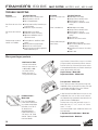
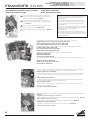
More great Logan products…
#708 Extension Table
Laminate surface board
extension that mounts on
to #650, #655 or #660
mat cutters. Allows
border sizes up to 17”
using parallel mat guide.
Logan Surface V-Groover Offers a way to cut surface
V-Grooves quickly and accurately with zero overcuts.
Push-Pull action cuts V-Grooves right on the surface
of the matboard eliminating any need for trimming or
taping. Works entirely with stops.
Logan V-Groover - Model #705
Replacement Blades - Model #1258
Freestyle Cutter - Model 1100
Push or pull style cutter with ergonomic shape and
fixed blade. Great for freestyle mat cutting. Use right
or left handed. Available in two colors: Red and
Silver. Three extra blades included.
Foamboard Cutter -
Model 1500
Push style fixed blade
cutter can be used against
any suitable straight edge.
Reversible, it cuts 90° or
45° bevel with an
adjustable blade to a
foamboard thickness of
1/8” (3mm), 3/16” (5mm)
and 3/8” (10mm). Includes
three extra blades.
3-Step Oval and Circle Mat Cutter is easy to use, fast
and portable. Cuts ovals or circles on the surface of
the matboard using a patented 3-step mechanism for
gradual increase of blade depth.
Converts from oval to circle cutter with a turn of a
knob. Ovals from 3 1/4” x 4 3/4” to 20” x 23”. Circles
from 4 1/2” to 20”.
Uses common blade. Logan - Model 324, Dexter or X-
Acto equivalent.
3-Step Oval & Circle Mat Cutter - Model 201.
Replacement blades - Model 324.
Problem Possible Reasons

Logan Graphic Products Inc., 1100 Brown Street, Wauconda, IL 60084 Toll Free 1 800 331 6232 www.logangraphic.com
19
FRAMER'S EDGE
MAT CUTTER MODELS 650, 655 & 660
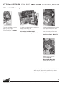
For more creative ideas in matting,
pick up a copy of Logan’s
“How To Cut Mats” Video by
Vivian C. Kistler, CPF. - Model 237.
Add personality to your mats
with the Logan Mat
Decoration Kit - Model 526
Includes decorative supplies &
instructions.
Complete and detailed directions featuring
Logan's picture framing tools system.
Learn inside secrets from professional
framers for creating your own custom
framed art.
Home Picture Framing - Model F245
Also available are 3 different books on matting and
framing by Vivian C. Kistler, CPF.
Basic Mat Cutting - Model 238-M.
Mat Decoration Book- Model 240-M.
Do It Yourself Picture Framing- Model 241-M.
See your local Logan Dealer for availability. Call at 800/331-6232 for
a dealer near you, or please check our 'where to buy' section on
Logan's website www.logangraphic.com
Also available from Logan…
La page est en cours de chargement...
La page est en cours de chargement...
La page est en cours de chargement...
La page est en cours de chargement...
La page est en cours de chargement...
La page est en cours de chargement...
La page est en cours de chargement...
La page est en cours de chargement...
La page est en cours de chargement...
La page est en cours de chargement...
La page est en cours de chargement...
La page est en cours de chargement...
La page est en cours de chargement...
La page est en cours de chargement...
La page est en cours de chargement...
La page est en cours de chargement...
La page est en cours de chargement...
La page est en cours de chargement...
La page est en cours de chargement...
La page est en cours de chargement...
La page est en cours de chargement...
La page est en cours de chargement...
La page est en cours de chargement...
-
 1
1
-
 2
2
-
 3
3
-
 4
4
-
 5
5
-
 6
6
-
 7
7
-
 8
8
-
 9
9
-
 10
10
-
 11
11
-
 12
12
-
 13
13
-
 14
14
-
 15
15
-
 16
16
-
 17
17
-
 18
18
-
 19
19
-
 20
20
-
 21
21
-
 22
22
-
 23
23
-
 24
24
-
 25
25
-
 26
26
-
 27
27
-
 28
28
-
 29
29
-
 30
30
-
 31
31
-
 32
32
-
 33
33
-
 34
34
-
 35
35
-
 36
36
-
 37
37
-
 38
38
-
 39
39
-
 40
40
-
 41
41
-
 42
42
-
 43
43


Logan Graphic Products 655 Le manuel du propriétaire
- Taper
- Le manuel du propriétaire
dans d''autres langues
Documents connexes


Autres documents
-
Logan 650 Le manuel du propriétaire
-
Logan 660 Le manuel du propriétaire
-
-
-
-
-
-
-
Logan 1100 Le manuel du propriétaire
-