Eaton Cooper Power System LCR 6600 RFN Instructional Leaflet
- Taper
- Instructional Leaflet

Instructional Leaflet
Technical Support: 1-800-815-2258
Introduction
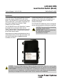
This instructional leaflet contains general installation
information for the LCR 6600 RFN Load Control
Switch. The LCR 6600 RFN is used to control remote
electric loads and it is activated by commands sent
over Eaton’s Cooper Power Systems’ Radio
Frequency (RF) mesh network.
The LCR 6600 RFN uses an RF SelectCom™ module
to provide two-way communication with the
Yukon™ master station. Once powered-up, the LCR
will automatically form a communication path back
to the Yukon master station.
Advanced security features provide both over-the-air
and local port security. All local port connections and
over-the-air commands are logged to provide
traceability of actions.
The data log records the actual time of state
changes, for the control relay and appliances, to
provide improved granularity of runtime and
shedtime information.
The LCR 6600 RFN addressing must be configured
for your demand response system prior to operation.
CAUTION
Observe precautions for handling
electrostatic sensitive devices.
MISE EN GARDE
Respecter les précautions
de manipulation des dispositifs
électrostatiques sensibles.
LCR 6600 RFN
Load Control Switch (Brazil)
WARNING
Dangerous voltages are present. Equipment damage, personal injury, and death can result if safety
precautions are not followed. Use authorized utility procedures to install, test, and service the LCR 6600 RFN.
AVERTISSEMENT
Présence de tensions dangereuses. Tout défaut de se conformer aux mesures de sécurité
peut entraîner un bris d'équipement, une blessure corporelle ou même la mort. Servez-vous des procédures
autorisées par l'entreprise de services pour installer, tester et entretenir le LCR 6600 RFN.

2 Instructional Leaflet
LCR 6600 RFN Load Control Switch
(Brazil)
SAFETY FOR LIFE
Eaton’s Cooper Power Systems™ products meet or exceed all applicable industry standards relating to product
safety. We actively promote safe practices in the use and maintenance of our products through our service
literature, instructional training programs, and the continuous efforts of all Eaton’s Cooper Power Systems
employees involved in product design, manufacture, marketing, and service.
We strongly urge that you always follow all locally approved safety procedures and safety instructions when working
around high voltage lines and equipment and support our “Safety For Life” mission.
SAFETY INFORMATION
The instructions in this manual are not intended as a
substitute for proper training or adequate experience in
the safe operation of the equipment described. Only
competent technicians who are familiar with this
equipment should install, operate, and service it.
A competent technician has these qualifications:
•
Is thoroughly familiar with these instructions.
•
Is trained in industry-accepted high- and low-voltage
safe operating practices and procedures.
•
Is trained in the electrical safety codes and standard
installation techniques that pertain to this type of
equipment.
•
Is trained in the use of safety equipment such as safety
glasses, hard hat, gloves, etc.
Following is important safety information. For safe
installation and operation of this equipment, be sure to
read and understand all cautions and warnings
.
Safety Instructions
Following are general caution and warning statements
that apply to this equipment. Additional statements,
related to specific tasks and procedures, are located
throughout the manual.
!
SAFETY
FOR LIFE
!
SAFETY
FOR LIFE
Hazard Statement Definitions
This document may contain four types of hazard
statements:
DANGER:
Indicates a hazardous situation which, if
not avoided, will result in death or serious injury.
WARNING:
Indicates a hazardous situation which, if
not avoided, could result in death or serious injury.
CAUTION:
Indicates a hazardous situation which,
if not avoided, could result in minor or moderate
injury
or equipment damage
.
CAUTION:
Indicates a potentially hazardous situation
which, if not avoided, may result in equipment damage only.
DANGER:
Hazardous voltage. Contact with
hazardous voltage will cause death or severe
personal injury. Follow all locally approved safety
procedures when working around high and
low-voltage lines and equipment.
G103.3
DANGER:
Before installing, operating,
maintaining, or testing this equipment, carefully
read and understand the contents of this
document. Improper operation, handling, or
maintenance can result in death, severe personal
injury, and equipment damage.
G101.0
DANGER:
This equipment is not intended to
protect human life. Follow all locally approved
procedures and safety practices when installing or
operating this equipment. Failure to comply may
result in death, severe personal injury, and
equipment damage.
G102.1

Eaton’s Cooper Power Systems 3
CT-Y0-0557
!
SAFETY
FOR LIFE
LA SÉCURITÉ C'EST LA VIE
Les produits Eaton’s Cooper Power Systems rencontrent et dépassent toutes les normes de sécurité industrielles
applicables. Nous encourageons activement les pratiques les plus sûres au cours de l'utilisation et de la
maintenance de nos produits dans nos manuels d'entretien, nos programmes de formation et les efforts
permanents de tous les employés de Eaton’s Cooper Power Systems participant à la conception, à la fabrication, à
la mise sur le marché et à l'entretien des produits.
Nous recommandons fortement de toujours suivre les procédures et instructions de sécurité locales lors d'une
intervention au voisinage de lignes et de matériel haute tension dans le cadre de notre initiative “La sécurité c'est la vie”.
INFORMATIONS DE SÉCURITÉ
Les instructions du présent manuel ne sont pas destinées
à se substituer à une formation ou à une expérience
adéquate pour l'utilisation sûre du matériel décrit. Seuls
des techniciens compétents et qui connaissent bien le
matériel sont habilités à l'installer, l'utiliser et l'entretenir.
Un technicien compétent dispose des qualifications
suivantes:
•
Il connaît parfaitement toutes ces instructions.
•
Il est formé aux pratiques et procédures de sécurité
industrielles acceptées en haute et basse tension.
•
Il a été formé dans les codes de sécurité électrique et
les techniques d'installation standard qui se
rapportent à ce type d'équipement.
•
Il est formé à l'entretien et à l'utilisation de
l'équipement de protection tel que vêtements
réfléchissants, lunettes de sécurité, casques de
chantier, gants, etc.
Cette page contient des informations importantes
concernant la sécurité. Pour l'installation et l'utilisation de
ce matériel en toute sécurité, veiller à lire et à bien
comprendre toutes les mises en garde et tous les
avertissements.
Instructions de Sécurité
Les consignes suivantes sont des mises en garde et
avertissements d'ordre général qui s'appliquent à ce
matériel. D'autres consignes relatives à des tâches et
des procédures spécifiques sont données tout au long
du manuel.
!
SAFETY
FOR LIFE
!
SAFETY
FOR LIFE
Définitions des mises en garde
Ce manuel contient quatre types de mises en garde:
DANGER:
Indique une situation de danger
immnente qui, si elle n’est pas évitée, entraînera
des blessures graves, voire, mortelles.
AVERTISSEMENT:
Indique une situation potentiel-
lement dangereuse qui, si elle n’est pas évitée, peut
entra
î
ner des blessure graves, voire mortelles
.
ATTENTION:
Indique une situation potentielle-
ment dangereuse qui, si elle n’est pas évitée, peut
entra
î
ner des blessures mineures ou modérées.
ATTENTION:
Indique une situation potentiellement
dangereuse qui, si elle n’est pas évitée, peut entraîner des
dégâts matériels.
DANGER: Tension dangereuse. Le contact
avec une tension dangereuse causera des bles-
sures graves, voire mortelles. Suivre toutes les
procédures de sécurité approuvées localement
pour toute intervention au voisinage de lignes et
de matériel à haute et basse tension.
G103.3
AVERTISSEMENT: Avant d'installer, d'utiliser,
d'entretenir ou de tester ce matériel, lire atten-
tivement et veiller à bien comprendre le contenu
de ce manuel. Une utilisation, une manutention
ou une maintenance incorrecte peut causer des
blessures graves ou mortelles, et des dégâts
matériels.
G101.0
AVERTISSEMENT: Ce matériel n'est pas un
dispositif de protection vitale. Se conformer à
toutes les procédures et pratiques de sécurité
approuvées localement pour l'installation et
l'utilisation de ce matériel. Faute de quoi, il y a
risque de mort, de blessures graves et de
dégâts matériels.
G102.1

4 Instructional Leaflet
LCR 6600 RFN Load Control Switch
(Brazil)
LCR 6600 RFN Regulatory Notices
NOTICE:
The Original Equipment Manufacturer (OEM) must ensure that FCC Labeling requirements are met. This
includes a clearly visible label on the outside of the OEM enclosure specifying the Eaton’s Cooper Power Systems
FCC identifier (FCC ID: P9X-RFNSCOMMMR3) and IC Number (IC: 6766A-RFNSCOMMMR3) as well as the FCC
Notice below.
NOTICE:
This device complies with Part 15 of the FCC Rules. Operation is subject to the following two conditions.
As such, the radio component of this device is intended only for OEM integrators under the following two conditions:
1. This device may not cause harmful interference, and
2. The transmitter module may not be co-located with any other transmitter or antenna.
NOTICE:
Changes or modifications not expressly approved by the party responsible for compliance could void the
user’s authority to operate the equipment.
NOTICE:
This equipment has been tested and found to comply with the limits for a Class B digital device, pursuant
to part 15 of the FCC Rules. These limits are designed to provide reasonable protection against harmful interference
in a residential installation. This equipment generates, uses and can radiate radio frequency energy and, if not
installed and used in accordance with the instructions, may cause harmful interference to radio communications.
However, there is no guarantee that interference will not occur in a particular installation.
If this equipment does cause harmful interference to radio or television reception, which can be determined by
turning the equipment off and on, the user is encouraged to try to correct the interference by one or more of the
following measures:
• Reorient or relocate the receiving antenna.
• Increase the separation between the equipment and receiver.
• Connect the equipment into an outlet on a circuit different from that to which the receiver is connected.
• Consult the dealer or an experienced radio/TV technician for help.
NOTICE:
The installer of this radio equipment must ensure that the antenna is located or pointed such that it does
not emit RF field in excess of Health Canada limits for the general population; consult Safety Code 6, obtainable from
Health Canada’s Web site: www.hc-sc.gc.ca.
NOTICE:
To comply with FCC RF exposure compliance requirements, the antenna used for this transmitter must be
installed to provide a separation distance of at least 20 cm from all persons and must not be co-located or operate
in conjunction with any other antenna or transmitter.
As such, the radio component of this device is intended only for OEM integrators under the following two conditions:
• The antenna must be installed such that 20 cm is maintained between the antenna and users.
• The transmitter module may not be co-located with any other transmitter or antenna.
As long as the two conditions above are met, further transmitter testing will not be required. However, the OEM
integrator is still responsible for testing their end product for any additional compliance requirements required with
this module installed (e.g., digital device emissions, PC peripheral requirements).
In the event that these conditions cannot be met (for example, co-location with another transmitter), then the FCC
authorization is no longer considered valid and the FCC ID cannot be used on the final product. In these
circumstances, the OEM integrator will be responsible for re-evaluating the end product (including the transmitter)
and obtaining a separate FCC authorization.
End Product Labeling
This transmitter module is authorized only for use in devices where the antenna may be installed such that 20 cm
may be maintained between the antenna and users (for example access points, routers, wireless ASDL modems,
certain laptop configurations, and similar equipment).
The final end product must be labeled in a visible area with
the following: “Contains FCC ID: P9X-RFNSCOMMMR3, IC: 6766A-RFNSCOMMMR3”.
The radio component is an integral part of the LCR 6600 RFN and it cannot be removed.

Eaton’s Cooper Power Systems 5
CT-Y0-0557
!
SAFETY
FOR LIFE
LCR 6600 RFN Réglementations
NOTIFICATION:
Le fabricant d'équipement d'origine (OEM) doit s'assurer que les exigences en matière d'étiquetage
FCC sont remplies. Cette comprend une étiquette clairement visible à l'extérieur du boîtier OEM précisant le numéro
d’identification FCC de Eaton’s Cooper Power Systems (FCC ID: P9X-RFNSCOMMMR3) et le numéro IC Number
(IC: 6766A-RFNSCOMMMR3) ainsi que l'avis FCC ci-dessous.
NOTIFICATION:
Cet appareil est conforme à la Partie 15 des règlements de la FCC. Son fonctionnement est soumis
aux deux conditions suivantes. En tant que tel, le composant radio de cet appareil est destiné uniquement aux
intégrateurs OEM sous les deux conditions suivantes:
1. Cet appareil ne doit pas provoquer d'interférences nuisibles, et
2. Le module émetteur peut ne pas être colocalisé avec un autre émetteur ou antenne.
NOTIFICATION:
Tout changement ou modification non expressément approuvés par la partie responsable de la
conformité pourraient annuler l'autorité de l'utilisateur à utiliser cet équipement.
NOTIFICATION:
Cet équipement a été testé et s'est avéré conforme aux limites pour un appareil numérique de
classe B, conformément à la partie 15 des règles de la FCC. Ces limites sont conçues pour fournir une protection
raisonnable contre les interférences nuisibles dans une installation résidentielle. Cet équipement génère, utilise et
peut émettre des fréquences radioélectriques et, s'il n'est pas installé et utilisé conformément aux instructions, il peut
causer des interférences nuisibles pour les communications radio. Cependant, il n'existe aucune garantie que des
interférences ne se produiront pas dans une installation particulière. Si cet équipement provoque des interférences
nuisibles à la réception radio ou télévision, ce qui peut être déterminé en l'éteignant et en le rallumant, l'utilisateur
est prié d’essayer de corriger l'interférence en prenant une ou plusieurs des mesures suivantes:
• Réorienter ou déplacer l'antenne de réception.
• Augmenter la distance entre l'équipement et le récepteur.
• Connecter l'équipement à une sortie sur un circuit différent de celui sur lequel est branché le récepteur.
• Consulter le revendeur ou un technicien radio / TV expérimenté.
NOTIFICATION:
L'installateur de cet équipement radio doit s'assurer que l'antenne est située ou orientée de telle
sorte qu'il ne pas émettre de champ RF dépassant les limites de Santé Canada pour la population générale; consulter
le Code de sécurité 6, disponible sur le site Web de Santé Canada: www.hc-sc.gc.ca.
NOTIFICATION:
Pour se conformer aux exigences de conformité de la FCC, l'antenne utilisée pour ce transmetteur
doit être installée pour fournir une distance de séparation d'au moins 20 cm de toute personne et ne doit pas être
co-localisée ou exploitée en conjonction avec aucune autre antenne ou transmetteur.
Le composant radio de cet appareil est destiné uniquement aux intégrateurs OEM sous les deux conditions
suivantes:
• L'antenne doit être installée de telle sorte qu’une distance de 20 cm soit maintenue entre l'antenne et les
utilisateurs.
• Le module émetteur peut ne pas être installé avec un autre émetteur ou antenne.
Tant que les deux conditions précitées sont remplies, d'autres tests de l'émetteur ne seront pas nécessaires.
Cependant, l’intégrateur OEM est toujours responsable de tester son produit final pour toutes les exigences de mise
en conformité supplémentaires nécessaires à ce module installé (par exemple, les émissions de périphériques
numériques, des exigences périphériques PC).
Dans le cas où ces conditions ne peuvent être remplies (par exemple, la co-localisation avec un autre émetteur),
l’autorisation de la FCC n'est plus considérée comme valide et le numéro d’identification FCC ne peut pas être utilisé
sur le produit final. Dans ces circonstances, l'intégrateur OEM sera responsable de réévaluer le produit final (y
compris l'émetteur) et d’obtenir une autorisation de la FCC.
Étiquetage du produit final
Ce module émetteur est autorisé uniquement pour une utilisation dans les appareils où l'antenne peut être installée
de telle sorte qu’une distance de 20 cm peut être maintenue entre l'antenne et les utilisateurs (par exemple des points
d'accès, routeurs, modems ASDL sans fil, certaines configurations d'ordinateurs portables et autres équipements
similaires).
Le produit final doit être étiqueté dans un endroit visible avec ce qui suit:
“Contient FCC ID: P9X-RFNSCOMMMR3, IC: 6766A-RFNSCOMMMR3”.
Le composant radio est une partie intégrante du LCR 6600 RFN et il ne peut pas être enlevé.

6 Instructional Leaflet
LCR 6600 RFN Load Control Switch
(Brazil)
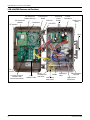
LCR 6600 RFN Features and Functions
Wiring Diagram
Location
LCR
Address Label
Low Current Relay
Locations with
Current Detection(2)
High Current
Relay
Test Button
RF SelectCom
Module
Wiring
Compartment
and Cover
Low Current
Relay Wires
HIgh Current
Relay Wires
VAC Power
Wires
LCR LEDs
IrDA Port
LCR Receiver
Board
RF Antenna
RF SelectCom
Module LEDs (2)
Current
Transformer
Switching
Power
Supply
Latch
FIP
Gasket
Divider

Eaton’s Cooper Power Systems 7
CT-Y0-0557
!
SAFETY
FOR LIFE
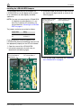
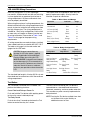
Installing the LCR 6600 RFN Jumpers
This procedure describes how to configure the
LCR 6600 RFN for use with digital control systems
on air conditioners or other digitally controlled
appliances.
NOTE:
If you are not connecting the LCR 6600 RFN
to a digitally controlled appliance, it is not
necessary to perform this procedure. You
may proceed with
“Mounting the LCR 6600
RFN” on page 8
.
The jumpers and relays are related as follows:
Prior to mounting or connecting power to the
LCR 6600 RFN, perform the following steps to install
the appropriate jumper(s) on the LCR circuit board:
1. Open the cover of the
LCR 6600 RFN.
2. Locate the jumper pins for each relay as
identified in the following figure.
3. Install the jumper on the relay or relays that will
be wired to the digital control as shown in the
following figure.
4. You are now ready to proceed with “Mounting
the LCR 6600 RFN” on page 8
.
Jumper Pins Relay
J14 K1 Relay 1
J15 K3 Relay 3
Digital Control Jumper
Pin J15 for Relay 3
(Low Power)
Digital Control Jumper
Pin J14 for Relay 1
Digital Control Jumper
Pin J15 for Relay 3
(Low Power)
Digital Control Jumper
Pin J14 for Relay 1

8 Instructional Leaflet
LCR 6600 RFN Load Control Switch
(Brazil)
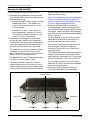
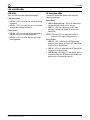
Mounting the LCR 6600 RFN
Perform the following steps to mount the LCR:
1. Determine which knockout(s) are to be used.
The
LCR 6600 RFN
contains five knockouts for
input and load wiring:
•
Knockouts A and D – Enters the Class 2 wiring
compartment (Class 1 if the divider is not
present). These knockouts are for 1/2 inch
(1.25 cm) conduit.
•
Knockouts B, C and E – Enters the Class 1
wiring compartment. Knockout B is for 3/4
inch (1.905 cm) conduit. Knockouts C and E
are for 1/2 inch (1.25 cm) conduit.
2. Remove the knockout prior to mounting by
using a drill and a conduit-style step drill bit.
The dimple in the center of the knockout allows
you to accurately position the step-drill bit in
the center of the knockout for a clean hole.
The knockout may also be removed by inserting a
screwdriver into the knockout slot at several
points and prying it out. Do not hit the knockout
directly, as this may damage the case.
For added flexibility, the LCR enclosure provides
two side-entry access holes, D and E.
Per the manufacturer’s instructions, install a
conduit fitting onto the LCR enclosure. A small
bead of weather-proof silicone should be used to
seal the conduit fitting to the face of the enclosure.
See the Cooper Crouse-Hinds Web site for UL
approved conduit fittings:
http://www.cooperindustries.com/content/pub
lic/en/crouse-hinds/commercial_products/
products/commercial_fittings/rigid_imc/steel_s
et_screw_rigidimcconduitfittings.html
3. Mount the
LCR 6600 RFN
at the desired
mounting location, which is preferably a flat,
non-vibrating surface. Tightening the screws on
an irregular surface may distort the mounting
tabs. This can cause the tabs to break or defeat
the rain-tight seal.
For best reception, mount the LCR four feet or
higher above the ground, on the exterior of a
structure, and away from metal surfaces.
Ensure that the front door has room to open at
least 90 degrees. The minimum required
clearance is 8 inches (20.3 cm) in front of the
mounting surface.
The LCR provides three pre-drilled mounting tabs.
Cooper Power Systems recommends #10 pan
head screws for mounting the LCR. The diameter
of the mounting holes is 1/4 inches (0.635 cm).
For a rain-tight rating, mount the LCR so that
Knockouts A, B and C are located at the bottom
of the unit facing the ground.
4. Perform the LCR installation and wiring
instructions described on the next page.
Knockout A Knockout CKnockout B
Knockout D Knockout E
Dimple for Positioning
the Step-Drill bit

Eaton’s Cooper Power Systems 9
CT-Y0-0557
!
SAFETY
FOR LIFE
Installing the LCR 6600 RFN
Perform the following steps to complete the LCR
installation:
1. Remove electrical power from the AC circuits
that are to supply the LCR and the load(s) to be
controlled.
2. Wire the LCR 6600 RFN according to the wiring
diagram located inside the LCR enclosure.
NOTE:
To wire the LCR 6600 RFN to a Dual Stage air
conditioner and perform Dual Stage
TrueCycle control, wire the output lead from
Relay 1 (K1) to the primary compressor and
wire the output lead from Relay 3 (K3) to the
secondary compressor
.
3. The LCR 6600 RFN uses a switching power
supply.
For 120/240 VAC, connect the red and black leads
to the power source as shown in the wiring
diagram.
For 24 VAC, connect the two red leads to the
power source as shown in the wiring diagram.
4. Apply electrical power to the
LCR 6600 RFN
.
5. If cold load pick-up is enabled, the appropriate
relays energize and the red LEDs are lit.
6. If desired, perform a test shed as described in
the section “Test Button” on page 10.
7. Record the LCR address and other necessary
information.
8. Close the LCR door, secure the latch, and
install a utility seal.
WARNING
Dangerous voltages are present.
Multiple disconnects may be required to de-
energize all circuits.
MISE EN GARDE
Présence de tensions
dangereuses. Plusieurs débranchements
peuvent être nécessaire afin de mettre tous
les circuits hors tension.

10 Instructional Leaflet
LCR 6600 RFN Load Control Switch
(Brazil)
LCR 6600 RFN Wiring Connections
Install the wiring within a 1/2 inch liquid-tight,
non-metallic, flexible conduit or make sure the wiring
is close nippled into an approved junction box or
wiring compartment. All power and control wires
must be properly terminated.
When using the enclosure’s wiring compartment, the
divider installed within the wiring compartment must
remain in place to isolate the low voltage wires from
the high voltage wires. The wiring compartment is
suitable for 1 and 2 relay configurations. Units with 3
or more relays will require an external junction box
for wiring termination. Please refer to
Table 1
and
Table 2
on this page for the proper wiring
requirements.
All wiring connections are made to factory-installed,
color-coded leads that are rated for 600 VAC, 105°C.
The table on this page lists the color codes and
gauges for the LCR leads.
The standard lead length is 8 inches (20.32 cm) and
these leads are for connections within the enclosure
wiring compartment.
Two output leads are supplied for each relay. No
polarity requirements apply. All relay leads are
attached via push-on connectors.
Test Button
The Test button, located on the LCR board, can
perform the following functions:
Cancel Cold Load Pickup at Power-On
Push and hold the Test button while applying power
to the unit to cancel cold load pickup.
Test Relay Control
Push for less than 5 seconds and release the Test
button to control the relay for 1 minute.
The relay control initiated by the Test button is
implemented as a standard timed load control
command, zero delay, and zero random extension.
This overrides any other currently implemented or
delayed control.
NOTE:
Pushing the Test button multiple times does
not increment the control time by an
additional amount of time
.
CAUTION
Incorrect connections can
damage the LCR when power is applied.
Follow all applicable Local and National
Electrical Codes when wiring the LCR.
MISE EN GARDE
Un branchement incorrect
peut endommager le LCR au moment de la
mise sous tension. Conformez-vous à tous les
codes de l'électricité locaux et nationaux
pertinents pour procéder au branchement du
LCR.
Table 1. Wire Colors and Gauge
Connection Lead Color Gauge
Common Black 18
120/240 VAC Red 18
L1 Power (24 VAC) Red 18
L2 Power (24 VAC) Red 18
Relay 1 Yellow 18
Relay 2 Blue 10
Relay 3 (Low Power) Orange 18
Relay 4 (High Power) Green 10
Table 2. Relay Configuration
Configuration
Large
Compartment
Small
Compartment
One Low Current
Relay
Power One Low Current
Relay
One Low Current
Relay and One
High Current Relay
Power plus
One High Current
Relay
One Low Current
Relay
Two Low Current
Relays
Two Low Current
Relays
Power
One High Current
Relay
One High Current
Relay
Power
3 or More Relays Junction Box is Required

Eaton’s Cooper Power Systems 11
CT-Y0-0557
!
SAFETY
FOR LIFE
LCR 6600 RFN LEDs
LCR LEDs
The LCR LEDs have the following meanings:
Load Status (Red)
•
LED Off
– LED is off when the load is not being
controlled.
•
LED On
– LED is on when the relay is activated
and the load is being controlled.
Power (Green)
•
LED On
– LED is on during normal operation to
indicate that the unit is receiving power.
•
LED Off
– LED is off when that the unit is not
receiving power.
RF SelectCom LEDs
The two RF SelectCom Module LEDs have the
following meanings:
Status (Blue)
•
LED On During Startup
– LED is on solid for 30
seconds during startup, then it turns off.
•
LED On
– LED is on solid when an RF radio
message is being transmitted or received in a
connection.
NOTE:
The blue LED is not illuminated when a
broadcast message is being received
.
Status (Green)
•
LED Off
– LED is off when the RF SelectCom
module has lost power or when the RF SelectCom
firmware has malfunctioned.
•
LED On
– LED is on solid when the RF SelectCom
firmware has malfunctioned.
•
LED Blinking
– LED blinks (1/2 second on and 1/2
second off) when the RF SelectCom module has
power and it is functioning normally.

LCR 6600 RFN Load Control Switch
(Brazil)
FCC COMPLIANCE STATEMENT
This device complies with Part 15 of the FCC Rules. Operation is subject to the following two conditions:
(1) This device may not cause harmful interference, and
(2) This device must accept any interference received, including interference that may cause undesired operation.
This equipment has been tested and found to comply with the limits for a Class B digital device, pursuant to part 15 of the FCC Rules.
These limits are designed to provide reasonable protection against harmful interference in a residential installation. This equipment
generates, uses and can radiate radio frequency energy and, if not installed and used in accordance with the instructions, may cause
harmful interference to radio communications. However, there is no guarantee that interference will not occur in a particular installation.
If this equipment does cause harmful interference to radio or television reception, which can be determined by turning the equipment
off and on, the user is encouraged to try to correct the interference by one or more of the following measures:
• Reorient or relocate the receiving antenna.
• Increase the separation between the equipment and receiver.
• Connect the equipment into an outlet on a circuit different from that to which the receiver is connected.
• Consult the dealer or an experienced radio/TV technician for help.
These devices operate under Part 15 of the FCC rules. Modifications to these devices not expressly authorized by
Eaton’s Cooper
Power Systems may affect your ability to legally operate these devices.
DISCLAIMER OF WARRANTIES AND LIMITATION OF LIABILITY
THERE ARE NO UNDERSTANDINGS, AGREEMENTS, REPRESENTATIONS, OR WARRANTIES, EXPRESS OR IMPLIED,
INCLUDING WARRANTIES OF MERCHANTABILITY OR FITNESS FOR A PARTICULAR PURPOSE, OTHER THAN THOSE
SPECIFICALLY SET OUT BY ANY EXISTING CONTRACT BETWEEN THE SELLER AND BUYER. ANY SUCH CONTRACT
STATES THE ENTIRE OBLIGATION OF SELLER. THE CONTENTS OF THIS INFORMATION LEAFLET SHALL NOT BECOME
PART OF OR MODIFY ANY SUCH PRIOR OR EXISTING AGREEMENT.
The information, recommendations, descriptions, and safety notations are based on Eaton’s Cooper Power Systems
experience and judgment. THIS INFORMATION SHOULD NOT BE CONSIDERED AS ALL-INCLUSIVE OR COVERING ALL
CONTINGENCIES. If further information is required, Eaton’s Cooper Power Systems should be consulted. In no event will
Eaton’s Cooper Power Systems be responsible to the user in contract, in tort (including negligence), strict liability or otherwise
for any special, indirect, incidental, or consequential damage or loss whatsoever; or claims against the user by its customers
resulting from use of information, recommendations, descriptions, or safety notations.
One Cooper | www.cooperpower.com | Online
Copyright © 2013 Eaton. All rights reserved.
Eaton, Cooper Power Systems, SelectCom and Yukon are valuable
trademarks of Eaton in the U.S. and other countries. You are not
permitted to use Eaton trademarks without the prior written consent of
Eaton.
CT-Y0-0557 REV1
!
SAFETY
FOR LIFE
LCR 6600 RFN Specifications
Communications
SelectCom Radio Frequency Mesh Network
Operating Frequency:
902 to 907.5 MHz and 915 to 928 MHz
License Free Band
RF Maximum Output Power:
30 dBm (1 W)
Data Rates:
38.4 kbps, 76.8 kbps and 153.6 kbps
Receiver Sensitivity:
-104 dBm (@ 1% PER, +25
C, 38.4 kbps)
-101 dBm (@ 1% PER, +25
C, 76.8 kbps)
-98 dBm (@ 1% PER, +25
C, 153.6 kbps)
Mode:
Frequency Hopping Spread Spectrum (FHSS)
Operating Requirements
Power Source:
120/240 VAC (±20%) at 50/60 Hz
24 VAC (-20%, +10%) at 50/60 Hz
Supply Output:
12 V ±5%, 12 W
Temperature:
-40º F to 131º F (-40º C to +55º C)
Relative Humidity:
0 to 95% non-condensing
Relay Control
Low Power:
Form C (SPDT) non-latching
Maximum Ratings:
Low Current Relays: 1 A at 28 VDC or 120 VAC
High Current Relays: 30 A at 240 VAC Resistive
or 28 VDC
Housing
IP56 rated, injection-molded, UV-stabilized
polycarbonate plastic. Rain-tight per UL916.
Box Dimensions (Including Mounting Tabs)
10.81 in. H x 7.68 in. W x 3.60 in. D
(27.46 cm H x 19.51 cm W x 9.14 cm D)
-
 1
1
-
 2
2
-
 3
3
-
 4
4
-
 5
5
-
 6
6
-
 7
7
-
 8
8
-
 9
9
-
 10
10
-
 11
11
-
 12
12


Eaton Cooper Power System LCR 6600 RFN Instructional Leaflet
- Taper
- Instructional Leaflet
dans d''autres langues
Autres documents
-
DeWalt DXMA1909935 Manuel utilisateur
-
 SCX Design O18/32507 4000mAh Wireless Power Bank Notebook Manuel utilisateur
-
Yamaha PM5000 Le manuel du propriétaire
-
-
Yamaha V1 Le manuel du propriétaire
-
Yamaha CL5 Le manuel du propriétaire
-
-
-
Yamaha V3 Le manuel du propriétaire
-
