ASROCK P4VM890 Le manuel du propriétaire
- Catégorie
- Cartes mères
- Taper
- Le manuel du propriétaire

11
11
1
ASRock P4VM890 Motherboard
EnglishEnglish
EnglishEnglish
English
Copyright Notice:Copyright Notice:
Copyright Notice:Copyright Notice:
Copyright Notice:
No part of this installation guide may be reproduced, transcribed, transmitted, or trans-
lated in any language, in any form or by any means, except duplication of documen-
tation by the purchaser for backup purpose, without written consent of ASRock Inc.
Products and corporate names appearing in this guide may or may not be registered
trademarks or copyrights of their respective companies, and are used only for identifica-
tion or explanation and to the owners’ benefit, without intent to infringe.
Disclaimer:Disclaimer:
Disclaimer:Disclaimer:
Disclaimer:
Specifications and information contained in this guide are furnished for informational
use only and subject to change without notice, and should not be constructed as a
commitment by ASRock. ASRock assumes no responsibility for any errors or omissions
that may appear in this guide.
With respect to the contents of this guide, ASRock does not provide warranty of any kind,
either expressed or implied, including but not limited to the implied warranties or
conditions of merchantability or fitness for a particular purpose. In no event shall
ASRock, its directors, officers, employees, or agents be liable for any indirect, special,
incidental, or consequential damages (including damages for loss of profits, loss of
business, loss of data, interruption of business and the like), even if ASRock has been
advised of the possibility of such damages arising from any defect or error in the guide
or product.
This device complies with Part 15 of the FCC Rules. Operation is subject to the
following two conditions:
(1) this device may not cause harmful interference, and
(2) this device must accept any interference received, including interference that
may cause undesired operation.
Published August 2007
Copyright©2007 ASRock INC. All rights reserved.
CALIFORNIA, USA ONLY
The Lithium battery adopted on this motherboard contains Perchlorate, a toxic
substance controlled in Perchlorate Best Management Practices (BMP) regulations
passed by the California Legislature. When you discard the Lithium battery in
California, USA, please follow the related regulations in advance.
“Perchlorate Material-special handling may apply, see
www.dtsc.ca.gov/hazardouswaste/perchlorate”
ASRock Website: http://www.asrock.com

ASRock P4VM890 Motherboard
22
22
2
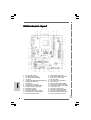
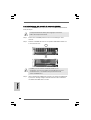
Motherboard LMotherboard L
Motherboard LMotherboard L
Motherboard L
ayoutayout
ayoutayout
ayout
EnglishEnglish
EnglishEnglish
English
1 PS2_USB_PWR1 Jumper 16 USB 2.0 Header (USB67, Blue)
2 ATX 12V Connector (ATX12V1) 17 Chassis Speaker Header (SPEAKER 1)
3 CPU Heatsink Retention Module 18 Serial Port Connector (COM1)
4 CPU Socket 19 AMR Slot (AMR1)
5 2 x 184-pin DDR DIMM Slots (DDR1, DDR2; Blue) 20 Clear CMOS Jumper (CLRCMOS1)
6 Infrared Module Header (IR1) 21 JR1 / JL1 Jumpers
7 Flash Memory 22 Front Panel Audio Header (AUDIO1)
8 Floppy Connector (FLOPPY1) 23 Internal Audio Connector: CD1 (Black)
9 Secondary IDE Connector (IDE2, Black) 24 Internal Audio Connector: AUX1 (White)
10 Primary IDE Connector (IDE1, Blue) 25 3 x PCI Slots (PCI1- 3)
11 North Bridge Controller 26 PCI Express x16 Slot (PCIE1)
12 South Bridge Controller 27 Chassis Fan Connector (CHA_FAN1)
13 Primary Serial ATA Connector (SATA1) 28 ATX Power Connector (ATXPWR1)
14 Secondary Serial ATA Connector (SATA2) 29 Shared USB 2.0 Header (USB4_5, Blue)
15 System Panel Header (PANEL1) 30 CPU Fan Connector (CPU_FAN1)

33
33
3
ASRock P4VM890 Motherboard
EnglishEnglish
EnglishEnglish
English
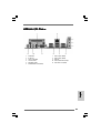
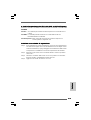
ASRock I/O PlusASRock I/O Plus
ASRock I/O PlusASRock I/O Plus
ASRock I/O Plus
TMTM
TMTM
TM
1 Parallel Port 7 USB 2.0 Ports (USB01)
2 RJ-45 Port 8 USB 2.0 Ports (USB23)
3 Line In (Light Blue) 9 VGA Port
4 Line Out (Lime) 10 PS/2 Keyboard Port (Purple)
5 Microphone (Pink) 11 PS/2 Mouse Port (Green)
6 Shared USB 2.0 Ports (USB45)

ASRock P4VM890 Motherboard
44
44
4
1. Introduction1. Introduction
1. Introduction1. Introduction
1. Introduction
Thank you for purchasing ASRock P4VM890 motherboard, a reliable motherboard
produced under ASRock’s consistently stringent quality control. It delivers excellent
performance with robust design conforming to ASRock’s commitment to quality and
endurance.
This Quick Installation Guide contains introduction of the motherboard and step-by-
step installation guide. More detailed information of the motherboard can be found in
the user manual presented in the Support CD.
Because the motherboard specifications and the BIOS software might
be updated, the content of this manual will be subject to change
without notice. In case any modifications of this manual occur, the
updated version will be available on ASRock website without further
notice. You may find the latest VGA cards and CPU support lists on
ASRock website as well.
ASRock website
http://www.asrock.com
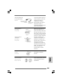
1.1 Package Contents1.1 Package Contents
1.1 Package Contents1.1 Package Contents
1.1 Package Contents
ASRock P4VM890 Motherboard
(Micro ATX Form Factor: 9.6-in x 8.0-in, 24.4 cm x 20.3 cm)
ASRock P4VM890 Quick Installation Guide
ASRock P4VM890 Support CD
One 80-conductor Ultra ATA 66/100/133 IDE Ribbon Cable
One Ribbon Cable for a 3.5-in Floppy Drive
One Serial ATA (SATA) Cable (Optional)
One Serial ATA (SATA) HDD Power Cable (Optional)
One ASRock I/O Plus
TM
Shield
One COM Port Bracket
EnglishEnglish
EnglishEnglish
English

55
55
5
ASRock P4VM890 Motherboard
EnglishEnglish
EnglishEnglish
English
1.21.2
1.21.2
1.2
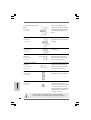
SpecificationsSpecifications
SpecificationsSpecifications
Specifications
Platform - Micro ATX Form Factor: 9.6-in x 8.0-in, 24.4 cm x 20.3 cm
CPU - Socket 478 for Intel
®
Pentium
®
4 / Celeron
®
D (Prescott,
Northwood, Willamate) processors
- FSB 800/533/400 MHz
- Supports Hyper-Threading Technology (see CAUTION 1)
- Supports Untied Overclocking Technology (see CAUTION 2)
Chipset - Northbridge: VIA
®
P4M890
- Southbridge: VIA
®
VT8237R Plus
Memory - 2 x DDR DIMM slots
- Support DDR400/333
- Max. capacity: 2GB
Hybrid Booster - CPU Frequency Stepless Control (see CAUTION 3)
- ASRock U-COP (see CAUTION 4)
- Boot Failure Guard (B.F.G.)
Expansion Slot - 3 x PCI slots
- 1 x PCI Express x16 slot
- 1 x AMR slot
Graphics - Integrated VIA
®
UniChrome Pro 3D/2D Graphics
- DirectX 7.0 VGA
- Max. shared memory 64MB
Audio - Realtek ALC653 5.1channel AC’97 audio codec
LAN - VIA
®
PHY VT6103
- Speed: 10/100 Ethernet
- Supports Wake-On-LAN
Rear Panel I/O ASRock I/O Plus
TM
- 1 x PS/2 Mouse Port
- 1 x PS/2 Keyboard Port
- 1 x VGA Port
- 1 x Parallel Port (ECP/EPP Support)
- 6 x Ready-to-Use USB 2.0 Ports
- 1 x RJ-45 LAN Port
- Audio Jack: Line in/Front Speaker/Microphone
Connector - 2 x Serial ATA 1.5 Gb/s connectors, support RAID (RAID 0,
RAID 1 and JBOD) and “Hot Plug” functions
- 2 x ATA133 IDE connectors (support 4 x IDE devices)
- 1 x Floppy connector
- 1 x IR header
- 1 x COM port header
- CPU/Chassis FAN connector

ASRock P4VM890 Motherboard
66
66
6
EnglishEnglish
EnglishEnglish
English
- 20 pin ATX power connector
- 4 pin 12V power connector
- CD in header
- AUX in header
- Front panel audio connector
- 2 x USB 2.0 headers (support 4 USB 2.0 ports; 2 of them are
shared with USB45 ports on the I/O panel)
(see CAUTION 5)
BIOS Feature - 4Mb AMI BIOS
- AMI Legal BIOS
- Supports “Plug and Play”
- ACPI 1.1 Compliance Wake Up Events
- Supports jumperfree
- AMBIOS 2.3.1 Support
Support CD - Drivers, Utilities, AntiVirus Software (Trial Version)
Hardware - CPU Temperature Sensing
Monitor - Chassis Temperature Sensing
- CPU Fan Tachometer
- Chassis Fan Tachometer
- Voltage Monitoring: +12V, +5V, +3.3V, Vcore
OS - Microsoft
®
Windows
®
2000 / XP compliant
Certifications - FCC, CE, WHQL
WARNING
Please realize that there is a certain risk involved with overclocking, including adjusting
the setting in the BIOS, applying Untied Overclocking Technology, or using the third-
party overclocking tools. Overclocking may affect your system stability, or even
cause damage to the components and devices of your system. It should be done at
your own risk and expense. We are not responsible for possible damage caused by
overclocking.

77
77
7
ASRock P4VM890 Motherboard
EnglishEnglish
EnglishEnglish
English
CAUTION!
1. About the setting of “Hyper Threading Technology”, please check page 26
of “User Manual” in the support CD.
2. This motherboard supports Untied Overclocking Technology. Please read
“Untied Overclocking Technology” on page 19 for details.
3. Although this motherboard offers stepless control, it is not recommended
to perform over-clocking. Frequencies other than the recommended CPU
bus frequencies may cause the instability of the system or damage the
CPU.
4. While CPU overheat is detected, the system will automatically shutdown.
Before you resume the system, please check if the CPU fan on the
motherboard functions properly and unplug the power cord, then plug it
back again. To improve heat dissipation, remember to spray thermal
grease between the CPU and the heatsink when you install the PC system.
5. Power Management for USB 2.0 works fine under Microsoft
®
Windows
®
XP
SP1 or SP2 / 2000 SP4.

ASRock P4VM890 Motherboard
88
88
8
EnglishEnglish
EnglishEnglish
English
2.2.
2.2.
2.
InstallationInstallation
InstallationInstallation
Installation
P4VM890 is a Micro ATX form factor (9.6-in x 8.0-in, 24.4 cm x 20.3 cm) motherboard.
Before you install the motherboard, study the configuration of your chassis to en-
sure that the motherboard fits into it.
Pre-installation PrecautionsPre-installation Precautions
Pre-installation PrecautionsPre-installation Precautions
Pre-installation Precautions
Take note of the following precautions before you install motherboard com-
ponents or change any motherboard settings.
1. Unplug the power cord from the wall socket before touching any
component.
2. To avoid damaging the motherboard components due to static electricity,
NEVER place your motherboard directly on the carpet or the like. Also
remember to use a grounded wrist strap or touch a safety grounded
object before you handle components.
3. Hold components by the edges and do not touch the ICs.
4. Whenever you uninstall any component, place it on a grounded anti-
static pad or in the bag that comes with the component.
Before you install or remove any component, ensure that the power is
switched off or the power cord is detached from the power supply.
Failure to do so may cause severe damage to the motherboard,
peripherals, and/or components.

99
99
9
ASRock P4VM890 Motherboard
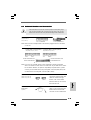
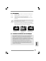
2.1 CPU Installation2.1 CPU Installation
2.1 CPU Installation2.1 CPU Installation
2.1 CPU Installation
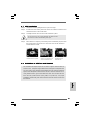
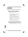
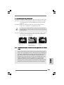
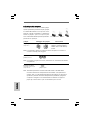
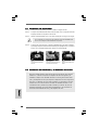
Step 1. Unlock the socket by lifting the lever up to a 90° angle.
Step 2. Position the CPU directly above the socket such that its marked corner
matches the base of the socket lever.
Step 3. Carefully insert the CPU into the socket until it fits in place.
The CPU fits only in one correct orientation. DO NOT force the
CPU into the socket to avoid bending of the pins.
Step 4. When the CPU is in place, press it firmly on the socket while you push down
the socket lever to secure the CPU. The lever clicks on the side tab to
indicate that it is locked.
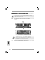
2.2 Installation of CPU Fan and Heatsink2.2 Installation of CPU Fan and Heatsink
2.2 Installation of CPU Fan and Heatsink2.2 Installation of CPU Fan and Heatsink
2.2 Installation of CPU Fan and Heatsink
This motherboard adopts 478-pin CPU socket to support Intel
®
Pentium
®
4
/
Celeron
®
CPU. It requires larger heatsink and cooling fan to dissipate heat.
You also need to spray thermal grease between the CPU and the heatsink to
improve heat dissipation. Make sure that the CPU and the heatsink are se-
curely fastened and in good contact with each other. Then connect the CPU
fan to the CPU_FAN connector (CPU_FAN1, see p.2 No. 30). For proper
installation, please kindly refer to the instruction manuals of the CPU fan and
the heatsink.
STEP 1:
Lift The Socket Lever Up to 90°
STEP 2/STEP 3:
Match The CPU Marked Corner
to The Socket Marked Corner
STEP 4:
Push Down And Lock
The Socket Lever
Lift Lever Up to 90°
CPU Marked Corner
Socket Marked Corner
EnglishEnglish
EnglishEnglish
English

ASRock P4VM890 Motherboard
1010
1010
10
EnglishEnglish
EnglishEnglish
English
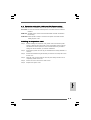
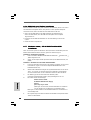
2.3 Installation of Memory Modules (DIMM)2.3 Installation of Memory Modules (DIMM)
2.3 Installation of Memory Modules (DIMM)2.3 Installation of Memory Modules (DIMM)
2.3 Installation of Memory Modules (DIMM)
P4VM890 motherboard provides two 184-pin DDR (Double Data Rate) DIMM slots.
Please make sure to disconnect power supply before adding or removing
DIMMs or the system components.
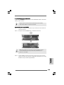
Step 1. Unlock a DIMM slot by pressing the retaining clips outward.
Step 2. Align a DIMM on the slot such that the notch on the DIMM matches the break
on the slot.
The DIMM only fits in one correct orientation. It will cause
permanent damage to the motherboard and the DIMM if you
force the DIMM into the slot at incorrect orientation.
Step 3. Firmly insert the DIMM into the slot until the retaining clips at both ends fully
snap back in place and the DIMM is properly seated.

1111
1111
11
ASRock P4VM890 Motherboard
EnglishEnglish
EnglishEnglish
English
2.4 Expansion Slots (PCI, AMR and PCI Express Slots)2.4 Expansion Slots (PCI, AMR and PCI Express Slots)
2.4 Expansion Slots (PCI, AMR and PCI Express Slots)2.4 Expansion Slots (PCI, AMR and PCI Express Slots)
2.4 Expansion Slots (PCI, AMR and PCI Express Slots)
There are 3 PCI slots, 1 AMR slot, and 1 PCI Express slot on this motherboard.
PCI slots: PCI slots are used to install expansion cards that have the 32-bit PCI
interface.
AMR slot: The AMR slot is used to insert an ASRock MR card with v.92 Modem
functionality.
PCIE Slots: PCIE1 (PCIE x16 slot) is used for PCI Express cards with x16 lane
width graphics cards.
Installing an expansion cardInstalling an expansion card
Installing an expansion cardInstalling an expansion card
Installing an expansion card
Step 1. Before installing the expansion card, please make sure that the power
supply is switched off or the power cord is unplugged. Please read the
documentation of the expansion card and make necessary hardware
settings for the card before you start the installation.
Step 2. Remove the system unit cover (if your motherboard is already installed in a
chassis).
Step 3. Remove the bracket facing the slot that you intend to use. Keep the screws
for later use.
Step 4. Align the card connector with the slot and press firmly until the card is
completely seated on the slot.
Step 5. Fasten the card to the chassis with screws.
Step 6. Replace the system cover.

ASRock P4VM890 Motherboard
1212
1212
12
EnglishEnglish
EnglishEnglish
English
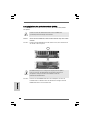
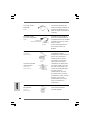
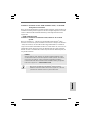
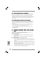
2.5 Jumpers Setup2.5 Jumpers Setup
2.5 Jumpers Setup2.5 Jumpers Setup
2.5 Jumpers Setup
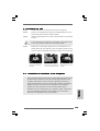
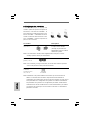
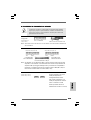
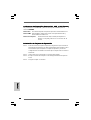
The illustration shows how jumpers are
setup. When the jumper cap is placed on
pins, the jumper is “Short”. If no jumper cap
is placed on pins, the jumper is “Open”. The
illustration shows a 3-pin jumper whose pin1
and pin2 are “Short” when jumper cap is
placed on these 2 pins.
Jumper Setting
PS2_USB_PWR1 Short pin2, pin3 to enable
(see p.2, No. 1) +5VSB (standby) for PS/2
or USB wake up events.
Note: To select +5VSB, it requires 2 Amp and higher standby current provided
by power supply.
JR1(see p.2, No. 21)
JL1(see p.2, No. 21)
Note: If the jumpers JL1 and JR1 are short, both the front panel and the rear panel
audio connectors can work.
Clear CMOS
(CLRCMOS1, 2-pin jumper)
(see p.2, No. 24)
Note: CLRCMOS1 allows you to clear the data in CMOS. The data in CMOS includes
system setup information such as system password, date, time, and system
setup parameters. To clear and reset the system parameters to default setup,
please turn off the computer and unplug the power cord from the power
supply. After waiting for 15 seconds, use a jumper cap to short 2 pins on
CLRCMOS1 for 5 seconds.
Short
Open
2-pin jumper

1313
1313
13
ASRock P4VM890 Motherboard
EnglishEnglish
EnglishEnglish
English
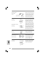
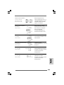
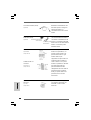
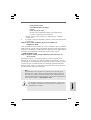
2.6 Onboard Headers and Connectors2.6 Onboard Headers and Connectors
2.6 Onboard Headers and Connectors2.6 Onboard Headers and Connectors
2.6 Onboard Headers and Connectors
Onboard headers and connectors are NOT jumpers. Do NOT place jumper
caps over these headers and connectors. Placing jumper caps over the
headers and connectors will cause permanent damage of the motherboard!
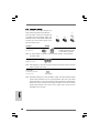
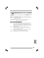
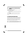
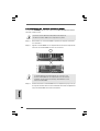
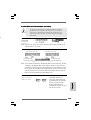
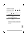
FDD Connector
(33-pin FLOPPY1)
(see p.2, No. 8)
Note: Make sure the red-striped side of the cable is plugged into Pin1 side of the
connector.
Primary IDE Connector (Blue) Secondary IDE Connector (Black)
(39-pin IDE1, see p.2, No. 10) (39-pin IDE2, see p.2, No. 9)
Note: If you use only one IDE device on this motherboard, please set the IDE
device as “Master”. Please refer to the instruction of your IDE device vendor
for the details. Besides, to optimize compatibility and performance, please
connect your hard disk drive to the primary IDE connector (IDE1, blue) and
CD-ROM to the secondary IDE connector (IDE2, black).
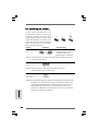
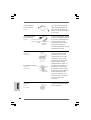
Serial ATA Connectors These two Serial ATA (SATA)
(SATA1: see p.2, No. 13) connectors support SATA data
(SATA2: see p.2, No. 14) cables for internal storage
devices. The current SATA
interface allows up to 1.5 Gb/s
data transfer rate.
Serial ATA (SATA) Either end of the SATA data
Data Cable cable can be connected to the
(Optional) SATA hard disk or the SATA
connector on the motherboard.
connect the black end
to the IDE devices
connect the blue end
to the motherboard
80-conductor ATA 66/100/133 cable
the red-striped side to Pin1
SATA1SATA2

ASRock P4VM890 Motherboard
1414
1414
14
EnglishEnglish
EnglishEnglish
English
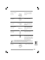
Serial ATA (SATA) Please connect the black end of
Power Cable SATA power cable to the power
(Optional) connector on the drive. Then
connect the white end of SATA
power cable to the power
connector of the power supply.
USB 2.0 Header Besides six default USB 2.0
(9-pin USB67) ports on the I/O panel, there are
(see p.2, No. 16) two USB 2.0 headers on this
motherboard. Each USB 2.0
header cansupport two USB
2.0 ports. The shared USB 2.0
header (USB4_5) is shared with
Shared USB 2.0 Header USB ports 45 on the I/O panel.
(9-pin USB4_5) When using the front panel USB
(see p.2, No. 29) ports by attaching the front panel
USB cable to USB4_5 header,
the USB ports 45 on the I/O panel
will not be able to function.
Infrared Module Header This header supports an optional
(5-pin IR1) wireless transmitting and
(see p.2, No. 6) receiving infrared module.
Internal Audio Connectors These connectors allow you
(4-pin CD1, 4-pin AUX1) to receive stereo audio input
(CD1: see p.2, No. 23) from sound sources such as
(AUX1: see p.2, No. 24) a CD-ROM, DVD-ROM, TV
tuner card, or MPEG card.
Front Panel Audio Header This is an interface for the front
(8-pin AUDIO1) panel audio cable that allows
(see p.2, No. 22) convenient connection and
control of audio devices.
connect to the
power supply
connect to the SATA
HDD power connector
CD1 AUX1

1515
1515
15
ASRock P4VM890 Motherboard
EnglishEnglish
EnglishEnglish
English
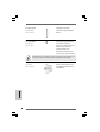
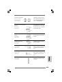
System Panel Header This header accommodates
(9-pin PANEL1) several system front panel
(see p.2, No. 15) functions.
Chassis Speaker Header Please connect the chassis
(4-pin SPEAKER 1) speaker to this header.
(see p.2, No. 17)
Chassis Fan Connector Please connect the chassis fan
(3-pin CHA_FAN1) cable to this connector and
(see p.2, No. 27) match the black wire to the
ground pin.
CPU Fan Connector Please connect the CPU fan
(3-pin CPU_FAN1) cable to this connector and
(see p.2, No. 30) match the black wire to the
ground pin.
ATX Power Connector Please connect an ATX power
(20-pin ATXPWR1) supply to this connector.
(see p.2, No. 28)
ATX 12V Connector Please note that it is necessary
(4-pin ATX12V1) to connect a power supply with
(see p.2, No. 2) ATX 12V plug to this connector
so that it can provides sufficient
power. Failing to do so will cause
the failure to power up.
Serial port connector This COM1 connector
(9-pin COM1) supports a serial port module.
(see p.2, No. 18)
Please install the heatsink and the CPU fan before installing ATX 12V
connector; otherwise, it may cause permanent damage!

ASRock P4VM890 Motherboard
1616
1616
16
EnglishEnglish
EnglishEnglish
English
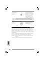
2.7 Serial A2.7 Serial A
2.7 Serial A2.7 Serial A
2.7 Serial A
TT
TT
T
A (SAA (SA
A (SAA (SA
A (SA
TT
TT
T
A) Hard Disks InstallationA) Hard Disks Installation
A) Hard Disks InstallationA) Hard Disks Installation
A) Hard Disks Installation
This motherboard adopts VIA
®
VT8237R Plus southbridge chipset that supports
Serial ATA (SATA) hard disks and RAID (RAID 0, RAID 1 and JBOD) functions. You
may install SATA hard disks on this motherboard for internal storage devices. This
section will guide you to install the SATA hard disks.
STEP 1: Install the SATA hard disks into the drive bays of your chassis.
STEP 2: Connect the SATA power cable to the SATA hard disk.
STEP 3: Connect one end of the SATA data cable to the motherboard’s SATA
connector.
STEP 4: Connect the other end of the SATA data cable to the SATA hard disk.
2.8 Hot Plug and Hot Swap F2.8 Hot Plug and Hot Swap F
2.8 Hot Plug and Hot Swap F2.8 Hot Plug and Hot Swap F
2.8 Hot Plug and Hot Swap F
unctions for SAunctions for SA
unctions for SAunctions for SA
unctions for SA
TT
TT
T
A HDDsA HDDs
A HDDsA HDDs
A HDDs
P4VM890 motherboard supports Hot Plug and Hot Swap functions for
SATA Devices.
NOTE
What is Hot Plug Function?
If the SATA HDDs are NOT set for RAID configuration, it is called “Hot
Plug” for the action to insert and remove the SATA HDDs while the system
is still power-on and in working condition.
However, please note that it cannot perform Hot Plug if the OS has been
installed into the SATA HDD.
What is Hot Swap Function?
If SATA HDDs are built as RAID1 then it is called “Hot Swap” for the action
to insert and remove the SATA HDDs while the system is still power-on
and in working condition.
2.92.9
2.92.9
2.9
Driver Installation GuideDriver Installation Guide
Driver Installation GuideDriver Installation Guide
Driver Installation Guide
To install the drivers to your system, please insert the support CD to your optical
drive first. Then, the drivers compatible to your system can be auto-detected and
listed on the support CD driver page. Please follow the order from up to bottom
side to install those required drivers. Therefore, the drivers you install can work
properly.

1717
1717
17
ASRock P4VM890 Motherboard
EnglishEnglish
EnglishEnglish
English
2.112.11
2.112.11
2.11
Installing WindowsInstalling Windows
Installing WindowsInstalling Windows
Installing Windows
®
2000 / XP With RAID Functions 2000 / XP With RAID Functions
2000 / XP With RAID Functions 2000 / XP With RAID Functions
2000 / XP With RAID Functions
If you want to install Windows
®
2000 / Windows
®
XP OS on your SATA
HDDs with RAID functions, please follow below steps.
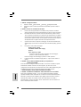
STEP 1: Set up BIOS.
A. Enter BIOS SETUP UTILITY Advanced screen IDE Configuration.
B. Set the “SATA Operation Mode” option to [RAID].
STEP 2: Make a SATA driver diskette.
A. Insert the ASRock Support CD into your optical drive to boot your system.
B. During POST at the beginning of system boot-up, press <F11> key, and
then a window for boot devices selection appears. Please select CD-
ROM as the boot device.
C. When you see the message on the screen, “Generate Serial ATA driver
diskette [YN]?”, press <Y>.
D. Then you will see these messages,
Please insert a blank
formatted diskette into floppy
drive A:
press any key to start
Please insert a floppy diskette into the floppy drive, and press any key.
E. The system will start to format the floppy diskette and copy SATA drivers
into the floppy diskette.
STEP 3: Use “RAID Installation Guide” to set RAID configuration.
Before you start to configure RAID function, you need to check the RAID installation
guide in the Support CD for proper configuration. Please refer to the document in the
following path in the Support CD:
.. \ RAID Installation Guide
STEP 4: Install Windows
®
2000 / XP OS on your system.
After step1, 2, 3, you can start to install Windows
®
2000 / Windows
®
XP OS on your
system. At the beginning of Windows
®
setup, press F6 to install a third-party RAID
driver. When prompted, insert the SATA driver diskette containing the VIA
®
RAID
driver. After reading the floppy disk, the driver will be presented. Select the driver to
install according to the mode you choose and the OS you install.
2.102.10
2.102.10
2.10
AMR Card and Driver Installation AMR Card and Driver Installation
AMR Card and Driver Installation AMR Card and Driver Installation
AMR Card and Driver Installation
If you do not insert AMR card to this motherboard, and you finish installing all
drivers to your system now, but in the future, you plan to use AMR card function
on this motherboard, please follow the steps below then.
1. Insert AMR card to AMR slot on this motherboard. Please make sure that the
AMR card is completely seated on the slot.
2. Install AMR card driver from our support CD to your system.
3. Reboot your system.

ASRock P4VM890 Motherboard
1818
1818
18
If you want to use “VIA RAID Tool” in Windows
®
environment, please install
SATA drivers from the Support CD again so that “VIA RAID Tool” will be
installed to your system as well.
NOTE. If you install Windows
®
2000 / Windows
®
XP on IDE HDDs and want to manage
(create, convert, delete, or rebuild) RAID functions on SATA HDDs, you still need to
set up “SATA Operation Mode” to [RAID] in BIOS first. Then, please set the RAID
configuration by using the document in the following path in the Support CD:
.. \ RAID Installation Guide
2.12 Installing Windows2.12 Installing Windows
2.12 Installing Windows2.12 Installing Windows
2.12 Installing Windows
®
2000 / XP Without RAID 2000 / XP Without RAID
2000 / XP Without RAID 2000 / XP Without RAID
2000 / XP Without RAID
FunctionsFunctions
FunctionsFunctions
Functions
If you want to install Windows
®
2000 / XP on your SATA HDDs without RAID functions,
please follow below steps.
STEP 1: Set up BIOS.
A. Enter BIOS SETUP UTILITY Advanced screen IDE Configuration.
B. Set the “SATA Operation Mode” option to [non-RAID].
STEP 2: Install Windows
®
2000 / XP OS on your system.
After setting up BIOS, you can start to install Windows
®
2000 / XP on your
system.
EnglishEnglish
EnglishEnglish
English

1919
1919
19
ASRock P4VM890 Motherboard
3. BIOS Information3. BIOS Information
3. BIOS Information3. BIOS Information
3. BIOS Information
The Flash Memory on the motherboard stores BIOS Setup Utility. When you start up
the computer, please press <F2> during the Power-On-Self-Test (POST) to enter
BIOS Setup utility; otherwise, POST continues with its test routines. If you wish to
enter BIOS Setup after POST, please restart the system by pressing <Ctl> + <Alt> +
<Delete>, or pressing the reset button on the system chassis.
The BIOS Setup program is designed to be user-friendly. It is a menu-driven program,
which allows you to scroll through its various sub-menus and to select among the
predetermined choices. For the detailed information about BIOS Setup, please refer
to the User Manual (PDF file) contained in the Support CD.
4. Software Suppor4. Software Suppor
4. Software Suppor4. Software Suppor
4. Software Suppor
t CD informationt CD information
t CD informationt CD information
t CD information
This motherboard supports various Microsoft
®
Windows
®
operating systems: 2000 /
XP. The Support CD that came with the motherboard contains necessary drivers and
useful utilities that will enhance motherboard features.
To begin using the Support CD, insert the CD into your CD-ROM drive. It will display
the Main Menu automatically if “AUTORUN” is enabled in your computer. If the Main
Menu does not appear automatically, locate and double-click on the file
“ASSETUP.EXE” from the BIN folder in the Support CD to display the menus.
EnglishEnglish
EnglishEnglish
English
2.132.13
2.132.13
2.13
Untied Overclocking TUntied Overclocking T
Untied Overclocking TUntied Overclocking T
Untied Overclocking T
echnologyechnology
echnologyechnology
echnology
This motherboard supports Untied Overclocking Technology, which means during
overclocking, FSB enjoys better margin due to fixed PCI / PCIE bus. You may set “CPU
Host Frequency” option of BIOS setup to [Auto], which will show you the actual CPU
host frequency in the following item. Therefore, CPU FSB is untied during overclocking,
but PCI / PCIE bus is in the fixed mode so that FSB can operate under a more stable
overclocking environment.
Please refer to the warning on page 6 for the possible overclocking risk before
you apply Untied Overclocking Technology.

ASRock P4VM890 Motherboard
2020
2020
20
DeutschDeutsch
DeutschDeutsch
Deutsch
1. Einführung1. Einführung
1. Einführung1. Einführung
1. Einführung
Wir danken Ihnen für den Kauf des ASRock P4VM890 Motherboard, ein zuverlässiges
Produkt, welches unter den ständigen, strengen Qualitätskontrollen von ASRock
gefertigt wurde. Es bietet Ihnen exzellente Leistung und robustes Design, gemäß der
Verpflichtung von ASRock zu Qualität und Halbarkeit.
Diese Schnellinstallationsanleitung führt in das Motherboard und die schrittweise
Installation ein. Details über das Motherboard finden Sie in der Bedienungsanleitung
auf der Support-CD.
Da sich Motherboard-Spezifikationen und BIOS-Software verändern können,
kann der Inhalt dieses Handbuches ebenfalls jederzeit geändert werden. Für
den Fall, dass sich Änderungen an diesem Handbuch ergeben, wird eine neue
Version auf der ASRock-Website, ohne weitere Ankündigung, verfügbar sein.
Die neuesten Grafikkarten und unterstützten CPUs sind auch auf der
ASRock-Website aufgelistet.
ASRock-Website: http://www.asrock.com
1.1 Kartoninhalt
ASRock P4VM890 Motherboard
(Micro ATX-Formfaktor: 24.4 cm x 20.3 cm; 9.6 Zoll x 8.0 Zoll)
ASRock P4VM890 Schnellinstallationsanleitung
ASRock P4VM890 Support-CD
Ein 80-adriges Ultra-ATA 66/100/133 IDE-Flachbandkabel
Ein Flachbandkabel für ein 3,5-Zoll-Diskettenlaufwerk
Ein Seriell-ATA- (SATA) Datenkabel (Option)
Ein Seriell-ATA (SATA) Festplattennetzkabel (Option)
Ein ASRock I/O Plus
TM
Shield
Ein COM Port-Anschlusshalter (Option)
La page est en cours de chargement...
La page est en cours de chargement...
La page est en cours de chargement...
La page est en cours de chargement...
La page est en cours de chargement...
La page est en cours de chargement...
La page est en cours de chargement...
La page est en cours de chargement...
La page est en cours de chargement...
La page est en cours de chargement...
La page est en cours de chargement...
La page est en cours de chargement...
La page est en cours de chargement...
La page est en cours de chargement...
La page est en cours de chargement...
La page est en cours de chargement...
La page est en cours de chargement...
La page est en cours de chargement...
La page est en cours de chargement...
La page est en cours de chargement...
La page est en cours de chargement...
La page est en cours de chargement...
La page est en cours de chargement...
La page est en cours de chargement...
La page est en cours de chargement...
La page est en cours de chargement...
La page est en cours de chargement...
La page est en cours de chargement...
La page est en cours de chargement...
La page est en cours de chargement...
La page est en cours de chargement...
La page est en cours de chargement...
La page est en cours de chargement...
La page est en cours de chargement...
La page est en cours de chargement...
La page est en cours de chargement...
La page est en cours de chargement...
La page est en cours de chargement...
La page est en cours de chargement...
La page est en cours de chargement...
La page est en cours de chargement...
La page est en cours de chargement...
La page est en cours de chargement...
La page est en cours de chargement...
La page est en cours de chargement...
La page est en cours de chargement...
La page est en cours de chargement...
La page est en cours de chargement...
La page est en cours de chargement...
La page est en cours de chargement...
La page est en cours de chargement...
La page est en cours de chargement...
La page est en cours de chargement...
La page est en cours de chargement...
La page est en cours de chargement...
La page est en cours de chargement...
La page est en cours de chargement...
La page est en cours de chargement...
La page est en cours de chargement...
La page est en cours de chargement...
La page est en cours de chargement...
La page est en cours de chargement...
La page est en cours de chargement...
La page est en cours de chargement...
La page est en cours de chargement...
La page est en cours de chargement...
La page est en cours de chargement...
La page est en cours de chargement...
La page est en cours de chargement...
-
 1
1
-
 2
2
-
 3
3
-
 4
4
-
 5
5
-
 6
6
-
 7
7
-
 8
8
-
 9
9
-
 10
10
-
 11
11
-
 12
12
-
 13
13
-
 14
14
-
 15
15
-
 16
16
-
 17
17
-
 18
18
-
 19
19
-
 20
20
-
 21
21
-
 22
22
-
 23
23
-
 24
24
-
 25
25
-
 26
26
-
 27
27
-
 28
28
-
 29
29
-
 30
30
-
 31
31
-
 32
32
-
 33
33
-
 34
34
-
 35
35
-
 36
36
-
 37
37
-
 38
38
-
 39
39
-
 40
40
-
 41
41
-
 42
42
-
 43
43
-
 44
44
-
 45
45
-
 46
46
-
 47
47
-
 48
48
-
 49
49
-
 50
50
-
 51
51
-
 52
52
-
 53
53
-
 54
54
-
 55
55
-
 56
56
-
 57
57
-
 58
58
-
 59
59
-
 60
60
-
 61
61
-
 62
62
-
 63
63
-
 64
64
-
 65
65
-
 66
66
-
 67
67
-
 68
68
-
 69
69
-
 70
70
-
 71
71
-
 72
72
-
 73
73
-
 74
74
-
 75
75
-
 76
76
-
 77
77
-
 78
78
-
 79
79
-
 80
80
-
 81
81
-
 82
82
-
 83
83
-
 84
84
-
 85
85
-
 86
86
-
 87
87
-
 88
88
-
 89
89


ASROCK P4VM890 Le manuel du propriétaire
- Catégorie
- Cartes mères
- Taper
- Le manuel du propriétaire
dans d''autres langues
- italiano: ASROCK P4VM890 Manuale del proprietario
- English: ASROCK P4VM890 Owner's manual
- español: ASROCK P4VM890 El manual del propietario
- Deutsch: ASROCK P4VM890 Bedienungsanleitung
Documents connexes
-
ASROCK 939NF4G-SATA2 Le manuel du propriétaire
-
ASROCK 775TWINS-HDTV Le manuel du propriétaire
-
ASROCK K8NF3-VSTA Le manuel du propriétaire
-
ASROCK K7UPGRADE-600 Le manuel du propriétaire
-
ASROCK 4CoreDual-VSTA Le manuel du propriétaire
-
ASROCK K10N78D Guide d'installation
-
ASROCK ALIVENF5-VSTA R2.0 Le manuel du propriétaire
-
ASROCK A780GM-LE-2203 Le manuel du propriétaire
-
ASROCK 4COREDUAL-SATA2 - 11-2007 Le manuel du propriétaire
-
ASROCK ALIVESATA2-GLAN Le manuel du propriétaire