IMC Networks MediaChassis/I-AC Guide d'installation
- Taper
- Guide d'installation

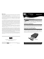
About the MediaChassis Series
The
MMeeddiiaaCChhaassssiiss
Series inlcudes 1-slot and 2-slot
modular chassis for use
with
iiMMccVV
Series modules. When installed in a MediaChassis, the module is
unmanaged, unless it has on-board SNMP logic (i.e. iMcV-FiberLinX). Each
MediaChassis features an internal 100-240 VAC ±10% power supply.
MediaChassis/2 is also available with 38-72 VDC power.
Installing the MediaChassis
Use the MediaChassis as a table-top chassis, or mount it into an equipment
rack or to a wall surface with the appropriate brackets (not included). Install the
MediaChassis chassis by placing it on a flat surface. Make sure to leave adequate
space on top of the unit to accommodate cooling.
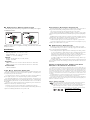
Configuring and Installing Modules
IMC Networks recommends turning the chassis’ power OFF before proceed-
ing. To install a module, slide the module into the chassis until the module is firm-
ly seated in the backplane. Secure the module to the chassis by tightening the
captive screw. Attach the network cables between the module and other devices
that will be interconnected. Plug the chassis into a power source.
NOTE
Refer to the installation guide shipped with your module for its configuration information.
Installing a module
into a MediaChassis/1
W ARRANTY
IMC Networks warrants to the original end-user purchaser that this product, EXCLUSIVE OF SOFTWARE, shall
be free from defects in materials and workmanship under normal and proper use in accordance with IMC
Networks' instructions and directions for a period of six (6) years after the original date of purchase. This war-
ranty is subject to the limitations set forth below.
At its option, IMC Networks will repair or replace at no charge the product which proves to be defective
within such warranty period. This limited warranty shall not apply if the IMC Networks product has been dam-
aged by unreasonable use, accident, negligence, service or modification by anyone other than an authorized
IMC Networks Service Technician or by any other causes unrelated to defective materials or workmanship.
Any replaced or repaired products or parts carry a ninety (90) day warranty or the remainder of the initial war-
ranty period, whichever is longer.
To receive in-warranty service, the defective product must be received at IMC Networks no later than the
end of the warranty period. The product must be accompanied by proof of purchase, satisfactory to IMC
Networks, denoting product serial number and purchase date, a written description of the defect and a Return
Merchandise Authorization (RMA) number issued by IMC Networks. No products will be accepted by IMC
Networks which do not have an RMA number. For an RMA num-ber, contact IMC Networks at PHONE: (800)
624-1070 (in the U.S and Canada) or (949) 465-3000 or FAX: (949) 465-3020. The end-user shall return the
defective product to IMC Networks, freight, customs and handling charges prepaid. End-user agrees to accept
all liability for loss of or damages to the returned product during shipment. IMC Networks shall repair or
replace the returned product, at its option, and return the repaired or new product to the end-user, freight
prepaid, via method to be determined by IMC Networks.
IMC Networks shall not be liable for any costs of procurement of substitute goods, loss of profits, or any
incidental, consequential, and/or special damages of any kind resulting from a breach of any applicable express
or implied warranty, breach of any obligation arising from breach of warranty, or otherwise with respect to the
manufacture and sale of any IMC Networks product, whether or not IMC Networks has been advised of the
possibility of such loss or damage.
EXCEPT FOR THE EXPRESS WARRANTY SET FORTH ABOVE, IMC NETWORKS MAKES NO OTHER WAR-
RANTIES, WHETHER EXPRESS OR IMPLIED, WITH RESPECT TO THIS IMC NETWORKS PRODUCT,
INCLUDING WITHOUT LIMITATION ANY SOFTWARE ASSOCIATED OR INCLUDED. IMC NETWORKS
SHALL DISREGARD AND NOT BE BOUND BY ANY REPRESENTATIONS OR WARRANTIES MADE BY ANY
OTHER PERSON, INCLUDING EMPLOYEES, DISTRIBUTORS, RESELLERS OR DEALERS OF IMC NETWORKS,
WHICH ARE INCONSISTENT WITH THE WARRANTY SET FORTH ABOVE. ALL IMPLIED WARRANTIES
INCLUDING THOSE OF MERCHANTABILITY AND FITNESS FOR A PARTICULAR PURPOSE ARE HEREBY
LIMITED TO THE DURATION OF THE EXPRESS WARRANTY STATED ABOVE.
Every reasonable effort has been made to ensure that IMC Networks product manuals and promotional
materials accurately describe IMC Networks product specifications and capabilities at the time of publication.
However, because of ongoing improvements and updating of IMC Networks products, IMC Networks cannot
guarantee the accuracy of printed materials after the date of publication and disclaims liability for changes,
errors or omissions.
MediaChassis
Installation
Guide
19772 Pauling • Foothill Ranch, CA 92610-2611 USA
TEL: (949) 465-3000 • FAX: (949) 465-3020
www.imc networks.com
© 2003-2004 IMC Networks. All rights reserved.
The information in this document is subject to change without notice. IMC Networks assumes no responsibility for any errors
that may appear in this document.
MediaChassis
is a trademark of IMC Networks. Other brands or product names may be
trademarks and are the property of their respective companies.
Document Number 50-80100-00 B1 September 2004
Networks
1
4

DC POWER S UPPLY W IRING I NSTRUCTIONS
The following chart states wiring configurations for 48 VDC power supplies
for MediaChassis/2-DC.
NOTE: The chassis is protected against mis-wiring; if mis-wired the chassis will
merely not function.
Specifications
Environmental:
Operating Temperature: 32° - 122° F (0° - 50° C)
Storage Temperature: 20° - 160° F (-20° - 70° C)
Humidity: 5 - 95% (non-condensing)
Electrical:
AC Input: 100-240 VAC ±10%, 50/60 Hz, 1A max.
DC Input: 38-72 VDC
Dimensions:
1 Slot: 1.55”H x 4.75”L x 7.31”D (3.94cm H x 12.07cm L x 18.57cm D)
2 Slot: 2.30”H x 4.75”L x 7.31”D (5.84cm H x 12.07cm L x 18.57cm D)
Heat Generation:
51 BTU/hr. maximum
F IBER O PTIC C LEANING G UIDELINES
Fiber Optic transmitters and receivers are extremely susceptible to contamination by particles of dirt
or dust which can obstruct the optic path and cause performance degradation. Good system perform-
ance requires clean optics and connector ferrules.
1) Use fiber patch cords (or connectors, if you terminate your own fiber) only from a reputable sup-
plier; low quality components can cause many hard-to-diagnose problems in an installation.
2) The manufacturer installs dust caps to ensure factory-clean optical devices. These protective caps
should not be removed until the moment of connecting the fiber cable to the device. Assure that the fiber
is properly terminated, polished and free of any dust or dirt and that the location is as free from dust and
dirt as possible.
3) Store spare caps in a dust-free environment such as a sealed plastic bag or box so that when rein-
stalled they do not introduce any contamination to the optics.
4) Should it be necessary to disconnect the fiber device, reinstall the protective dust caps.
5) If you suspect that the optics have been contaminated, alternate between blasting with clean, dry
compressed air and flushing with methanol to remove particles of dirt.
E LECTROSTATIC D ISCHARGE P RECAUTIONS
Electrostatic discharge (ESD) can cause damage to your add-in modules. Always observe the fol-
lowing precautions when installing or handling an add-in module or any board assembly.
1) Do not remove unit from its protective packaging until you're ready to install it.
2) Wear an ESD wrist grounding strap before handling any module or component. If you do not have
a wrist strap, maintain grounded contact with the system unit throughout any procedure requiring ESD pro-
tection.
WARNING! Integrated circuits and fiber optic components are extremely susceptible to electrostat-
ic discharge damage. Do not handle these components directly unless you are a qualified service tech-
nician and use tools and techniques that conform to accepted industry practices.
3) Hold boards by the edges only; do not touch the electronic components or gold connectors.
4) After removal, always place the boards on a grounded, static free surface, ESD pad or in a prop-
er ESD bag. Do not slide the board over any surface.
DC POWER S UPPLY P RECAUTIONS
The following precautions should be observed when installing chassis with DC power supplies.
1) Check nameplate ratings to assure there is no overloading of supply circuits that could have an
effect on overcurrent protection and supply wiring.
2) When installing 48V DC rated equipment, it must be installed only per the following conditions:
A) Connect the equipment to a 48V DC supply source that is electrically isolated form the alter-
nating current source. The 48V DC source is to be connected to a 48V DC SELV source.
B) Input wiring to terminal block must be routed and secured in such a manner that it is protect-
ed from damage and stress. Do not route wiring past sharp edges or moving parts.
C) A readily accessible disconnect device, with a 3mm minimum contact gap, shall be incorpo-
rated in the fixed wiring.
3) Grounding: reliable earthing of this equipment must be maintained. Particular attention should
be given to supply connections when connecting to power strips, rather than direct connections to the
branch circuit.
F EDERAL C OMMUNICATIONS C OMMISSION R ADIO
F REQUENCY I NTERFERENCE S TATEMENT
This equipment has been tested and found to comply with the limits for a Class B computing device, pur-
suant to Part 15 of the FCC Rules. These limits are designed to provide reasonable protection against harmful
interference when the equipment is operated in a commercial environment. This equipment generates, uses
and can radiate radio frequency energy and, if not installed and used in accordance with the instruction man-
ual, may cause harmful interference to radio communications. Operation of this equipment in a residential
area is likely to cause harmful interference in which the user will be required to correct the interference at his
own expense.
This digital apparatus does not exceed the Class B limits for radio noise emission from digital apparatus set
out in the Radio Interference Regulation of the Canadian Department of Communications.
Le présent appareil numérique n'émet pas de bruits radioélectriques dépassant les limites applicables aux
appareils numériques de classe B prescrites dans le Règlement sur le brouillage radioélectrique publié par le
ministère des Communications du Canada.
S AFETY C ERTIFICATIONS
UULL//CCUULL::
Listed to Safety of Information Technology Equipment, Including Electrical Business Equipment.
CCEE::
The products described herein comply with the Council Directive on Electromagnetic
Compatibility (89/336/EEC) and the Council Directive on Electrical Equipment Designed for use
within Certain Voltage Limits (73/23/EEC). Certified to Safety of Information Technology
Equipment, Including Electrical Business Equipment. For further details, contact IMC Networks.
Class 1 Laser product, Luokan 1 Laserlaite,
Laser Klasse 1, Appareil A’Laser de Classe 1
2 3
-
 1
1
-
 2
2


IMC Networks MediaChassis/I-AC Guide d'installation
- Taper
- Guide d'installation
dans d''autres langues
Documents connexes
-
 IMC Networks MediaChassis Series Mode d'emploi
-
 IMC Networks IE-MediaChassis/1 Mode d'emploi
-
 IMC Networks iMcV-S2SM/1250 Manuel utilisateur
-
 IMC Networks MiniMc-Gigabit Mode d'emploi
-
 IMC Networks IE-MiniMc Mode d'emploi
-
 IMC Networks Giga-MediaLinX Mode d'emploi
-
 IMC Networks Giga-MiniMc LFPT Mode d'emploi
-
 IMC Networks McPC MediaLinX Mode d'emploi
-
 IMC Networks Computer Hardware McPc-Gigabit Manuel utilisateur
-
 IMC Networks Giga-MiniMc Mode d'emploi


