Danby DWC140D1BSSPR Le manuel du propriétaire
- Catégorie
- Cave à vin
- Taper
- Le manuel du propriétaire

s. 01.
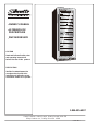
OWNER’S MANUAL
LE MANUEL DU
PROPRIÉTAIRE
DWC140D1BSSPR
CAUTION
Read and follow all safety rules
and operating instructions
before first use of this product.
PRÉCAUTION
Veuillez lire attentivement les
consignes de sécurité et les
instructions d’utilisation avant
l’utilisation initiale de ce produit.
Danby Products Limited, Guelph, Ontario Canada N1H 6Z9
Danby Products Inc., Findlay, Ohio USA 45840
V1.06.14
1-844-455-6097

Important Safety Information
Safety Precautions 3
Grounding Instructions 4
Operating Instructions
Features of Your Wine Cooler 5
The Controls of Your Wine Cooler 6
Setting the Temperature 6
7 egarotS eniW
7 snoitcurtsnI flehS
Installation Instructions
Tools You Will Need 8
Preparing the Enclosure 8
Care and Cleaning
Helpfull Hints 9
How to Clean the Inside 9
How to Clean the Outside 9
Trouble Shooting
Before Your Call For Service 10
3
5
9
11
1
8
Warranty
10
1
11
T
ABLE OF CONTENTS
Function Instruction 6
Moving &Vacations 9

2
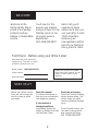
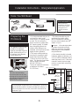
WELCOME
NEED HELP?
Welcome to the
Danby family. We’re
proud of our quality
products and we
believe in dependable
service.
You’ll see it in this
easy-to-use manual
and you’ll hear it in the
friendly voices of our
consumer service
department.
Tel:1-844-455-6097
Best of all, you’ll
experience these
values each time you
use your Wine Cooler.
That’s important,
because your
new appliance will be
part of your family for
Before you call for service,
there are a few things you
can do to help us serve
you better...
Read this manual
It contains instructions to
help you use and maintain
your appliance properly.
If you received a
damaged appliance
Immediately contact the
dealer (or builder) that sold
you the Wine Cooler.
Save time and money
Check the TroubleShooting
section before calling. This
section helps you solve
common problems thatmay
occur.
If you do need service, you
can relax knowing help is
only a phone call away.
Tel: 1-844-455-6097
Write down the model and serial
numbers here. They are on a label
Model number: DWC140D1BSSPR
Serial number:
Date purchased:
Staple your receipt to the inside
back cover of this manual. You will
need it to obtain service under
warranty.
Start Here!…Before using your Wine Cooler
many years to come.
located on the back of the unit.

READ ALL SAFETY INFORMATION BEFORE USING
3
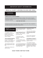
IMPORTANT SAFETY INFORMATION
WARNING
SAFETY
PRECAUTIONS
• This appliance must be
grounded. Connect only to a
properly grounded outlet.
See “Grounding Instructions”
section on page 4.
• Do not operate this appliance
if it has a damaged power cord
or plug, if it is not working
properly, or if the appliance has
been damaged or dropped.
• Do not splice the power cord
that is equipped with this appli-
ance.
• Keep power cord away from
heated surfaces.
• Do not immerse power cord,
plug or the appliance itself in
water.
• Do not use this product near
water-for example, in a wet
basement, near a swimming
pool or near a sink.
• Do not use corrosive
chemicals or vapors in this
appliance.
• Use this appliance only for
it’s intended use, as described
in this manual.
• Do not store perishable food
items such as (but not limited
to) meats and dairy products
in your Wine Cooler.
• Store Wine in sealed
containers only.
• See door surface cleaning
instructions in the Care and
Cleaning section(s) of this
manual.
• Do not cover or block any
openings on the appliance.
• This appliance is intended for
household use only. Do not
attempt to operate or store this
appliance outdoors.
• This appliance should be
serviced only by qualified serv-
ice personnel. Contact nearest
authorized service facility for
examination, repair or adjust-
ment.
SAVE THESE INSTRUCTIONS
DANGER, RISK OF CHILD ENTRAPMENT!
An empty wine cooler is a very dangerous attraction to children. Remove either the gasket,
latches, lids, lock and/or doors from unused or discarded appliances, or take some other action
to guarantee it harmless.
DON’T WAIT, DO IT NOW!
To reduce the risk of fire, burns, electric shock, or injury to persons when using your appliance,
follow basic precautions, including the following sections;

4
This appliance must be
grounded. In the event of an
electrical short circuit, ground-
ing reduces the risk of electric
shock by providing an escape
wire for the electric current.
This appliance is equipped
with a power cord having a
grounding wire with a ground-
ing plug. The plug must be
plugged into an outlet that is
properly installed and ground-
ed.
Consult a qualified electrician
or service technician if the
grounding instructions are not
completely understood, or if
doubt exists as to whether the
appliance is properly ground-
ed.
If the outlet is a standard 2-
prong wall outlet, it is your per-
sonal responsibility and obliga-
tion to have it replaced with a
properly grounded 3-prong
wall outlet.
For best operation, plug this
appliance into its own electri-
cal outlet to prevent flickering
of lights, blowing of fuse or
tripping of circuit breaker.
Do not under any circum-
stances cut or remove the
third (ground) prong from the
power cord.
Do not use an adapter plug
with this appliance.
Do not use an extension
cord with this appliance. If the
power cord is too short, have
a qualified electrician or serv-
ice technician install an outlet
near the appliance.
IMPORTANT SAFETY INFORMATION
Improper use of the
grounding plug can result
in a risk of electric shock.
Extreme Weight Hazard
Use two or more people
when moving the wine cooler.
Beneath the wine cooler there
are two leveling legs that are
located on either side of the
vent. It is important that your
wine cooler is level.
To level the wine cooler:
1. Move the wine cooler to
its final location.
2. Have someone gently lean
against the front of the wine
cooler to take some of the
weight off of the leveling
legs.
3. Turn the leveling legs
clockwise to raise the wine
cooler, or counter-clockwise
to lower it. Continue in this
manner until the wine
cooler is level. See Fig. A.
Raises
the Leg
(lowers
the unit)
Lowers
the Leg
(raises
the unit)
WARNING!
GROUNDING
INSTRUCTIONS
Leveling
Instructions
WARNING!

8
5
Operating Instructions
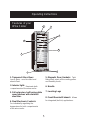
Features of your
Wine Cooler
1. Tempered Glass Door:
Low-E glass - used to reflect and
absorb heat.
4. Dual Electronic Controls:
For individually regulating the
temperature for both compartments
of the wine cooler.
5. Magnetic Door Gaskets: Tight
fitting seals retain all the cooling power
and humidity levels.
6. Handle
8. Front Mounted Exhaust:
Allows
for integrated
(built-in) applications.
7. Leveling Legs
6
1
5
2
2. Interior light:
Illuminate both
compartments of the wine cooler.
7
3
3. Full extension, ball baring glide
wood shelves with stainless
steel trim.
4

6
Operating Instructions
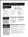
The Controls of your
Wine Cooler
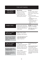
Function
instruction
Temperature Memory Function
Door Ajar Alarm Function
Temperature Alarm Function
NOTE
In the event of a power interruption the wine cooler can remember the
previous temperature settings, and when the power is restored the
cabinet temperature will go back to the same setting temperature as
before.
If the door is not closed completely the alarm will sound after 5 minutes.
Please close the door completely to avoid the loss of cold energy.
once or the door has not been
closed tightly, the unit will display the
after you close the door and
“HI” will disappear.
It is normal that the cabinet
shows “HI” or “LO” from time to time,
If it occurs frequently or lasts for a
long time, you can restart the unit by
unplugging it. If the problem
occurs once again after restart,
If too many bottles are put in at
"HI" signal in the display panel. This
is normal. Please wait 5 minutes
please contact customer service.
°
°
°
°
6
7
1.
Indicator light illuminates to signify the
cooling mode is currently in operation.
2.
Button
To control this appliance ON or OFF
(press and hold this buttons for
approximately 3 seconds).
3. Button
To control the inner light turn ON/OFF.
(If you press this button, the inner
light is not controlled by the reed
swith, and remains on.)
4. °C / °F
Adjacent indicator light denotes which
scale of temperature is displayed.
7.
Button
Used to set the temperature in
Button
5. Window
For viewing the temperature
of the upper zone.
6. Window
the upper zone (see ‘Setting the
Temperature’ below).
Used to set the temperature in
the lower zone (see ‘Setting the
Temperature’ below).
For viewing the temperature
of the lower zone.
If inner temperature is higher than 73°F(23°C), “HI” is shown
in the display panel, and the alarm will sound after one hour.
If inner temperature is lower than 32°F(0°C), “LO” is shown in the
display panel and the alarm will
sound. Refer to the trouble shooting
guide on page 10 for more information.
Setting the
Temperature
To switch the display
between the Fahrenheit (°F)
and Celsius (°C) scale,
depress the and
control buttons simultaneo-
usly for approximately
five(5) seconds.
The temperature range can
be set as low as 39°F(4°C)
or as high as 64°F (18°C) to
suit your specific storage
requirements. Each depres-
sion of the or but-
ton will allow you adjust the
temperature in 1° degree
increments within the afore-
mentioned range.
When you plug in your wine
cooler for the first time,
the temperatures will auto-
matically be set to 54°F
(12°C) in the upper zone and
to 45°F(7°C) in the lower zone,
and will be displayed in the
Fahrenheit scale (°F)
41
2
3
5

Operating Instructions
7
snoitcurtsnI flehS
!TNATROPMI
ton oD -ula htiw skcar revoc
-etam rehto yna ro liof munim
etauqeda tneverp lliw taht lair
-ibac eht nih
tiw noitalucric ria
.ten
To Remove Wine Shelves:
1. Fully extend the shelf you wish to remove (Fig. F)
2. Lift the front of the shelf up (Fig. F)
3. Holding the shelf track, push the shelf in, then up to release
from the rear dampers (Fig. G)
E.giF
D.giF
C.giF
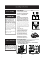
Wine Storage
IMPORTANT!
1. The upper zone
In order to achieve a maximum
capacity of 60 bottles the bottles
must be positioned alternately on
the upper six (6) shelves as shown
in Fig. D. This will allow for the
storage of 10 bottles per shelf on
each of the 6 shelves in this
chamber.
2. The lower zone
In order to achieve the maximum
capacity of 80 bottles,it will be
necessary to position the bottles
alternately on the upper six(6)
shelves,as shown in Fig.D. This
will allow for the storage of ten
(10) 750ml bottles per shelf on
each of the lower six (6) shelves.
On the bottom of cabinet
holds fifteen (15) 750ml bottles
when stocked according to Fig.E.
G .giFF .giF
The maximum capacity of the
DWC140D1BSSPR is 135
bottles.The upper zone will
hold a maximum of 60 bottles
and the lower zone a maximum
of 75 bottles. These capacities
are based on a standard 750ml
Bordeaux style bottles that are
3” in diameter. The actual
capacity will be dictated by the
size and shape of the bottles
and may be reduced depending
on these variables.
Only store unopened, sealed
bottles in the unit.
Alternatively, the spacing between
shelves is greater in the upper zone
and allows for the storage of larger
diameter bottles such as Pinot and
Burgundy with diameters up to 3 5/8”.
In order to achieve the optimum stor-
age, the bottles should be positioned
alternately on the upper six shelves
as shown in Fig. C. This will allow for
the storage of up to 9 bottles per shelf
for a reduced capacity of 54 bottles in
this zone.

8
Installation Instructions - Intergrated Application
Preparing the
Enclosure
Tools You Will Need
It is recommended that you do
not install the wine cooler
into a corner (i.e. directly beside
a wall). This is to allow the
door(s) to have a greater then
90° opening swing. A limited
door swing will prevent the
shelves from sliding out as
intended, and may lead to dam-
aging the door gasket(s).
The rough cabinet opening
must be on a level floor area
and at least 28 11/16” deep
(72.9cm) by 23 3/4”(60.1cm)
wide. The opening should also
have a height of at least
69 8/16 ”(176.5cm).
The electrical outlet may be
positioned from within either
side of the adjacent cabinetry
, or
the rear of the shaded area (as
shown in Fig D).
If the electrical outlet is located
inside the adjacent cabinetry, cut
a 1-1/2”(3.81cm) diameter hole to
admit the power cord. If the cabi-
net wall is metal, the hole edge
must be covered with a bushing
or grommet.
Fig
D
Important˖ If the electrical outlet
is surface mounted (not flush)
within the enclosure, the depth
requirement for the installation
may be affected.
stnemeriuqeR lacirtcelE
-noc eb tsum ecnailppa ehT
laudividni na ot detcen
lacirtcele dednuorg ylreporp
ro 51 a yb detcetorp ,teltuo
rekaerb tiucric erepma 02
.esuf yaled emit ro
FigE
}
}
}
}
69
8
/16
”
/
176.5cm
28
11
/16
/
72.9cm
Electrical
Access:1-1/2”/
3.81cm
23
3
/4
”
/
60.1cm
Cabinets
must be
square
and
plumb.
”
}
Top:2-1/2”/ 6.5cm
The top of cabinet should have
a deepness of at least
2-1/2”(6.5cm).
While performing
installations described
in this section, gloves,
safety glasses or
goggles should be
worn.
Tape measure
Carpenter square
Electric drill with hole bit
Gloves
Level
Safety goggles
Flashlight
)25<2856$)(7<
127(
This unit is front breathing.
Do not block the front air vent.
Blockage of the vent will result in
high operating temperatures and
system failure. (Fig.E)
*The listed depth requirement for the installation is assuming
that the electrical outlet is located in theadjacent cabinetry or
is flush mounted in the rear wall, not surface mounted in the
enclosure. Fig.D

9
Helpful Hints
NOTE: Be certain the
power is off before
cleaning any part of
this appliance.
Care and Cleaning
How to Clean
the Outside
Outer Case
It’s important to keep the area
clean where the door seals
against the cabinet. Clean this
area with a soapy cloth. Rinse
with a damp cloth and let dry
Door surface
Use only mild, non-abrasive
detergents applied with a
clean sponge or soft cloth.
Rinse well with damp cloth.
Control Panel and
Door
Wipe with a damp cloth and
dry thoroughly. Do not use
cleaning sprays, large
amounts of soap and water,
abrasive or sharp objects on
the panel-they can damage it.
Some paper towels may also
scratch the control panel and
door glass.
Do not use cleaners con-
taining ammonia or alcohol
on the wine cooler
Ammonia or alcohol can
damage the appearance of
the appliance.
How to Clean
the Inside
Walls, Floor, Inside
Window, and Shelves
Some water deposits and dust
can be removed with a dry
paper towel, others may
require a damp cloth.
Never use any commercial/
abrasive cleaners or sharp
objects on any part of the
wine cooler.
Moving &
Vacations
When Moving
1. Remove or securely fasten
down all loose items
inside the wine cooler.
2. To avoid damaging the
leveling screws, turn them
all the way into the base.
Vacation
For short vacation periods,
leave the controls at their
usual settings. During longer
absences;
1. Remove all bottles.
2. Disconnect from electrical
outlet.
3. Clean the wine cooler
thoroughly.
4. Leave the door open to
avoid formations of
condensate, mold or
odors.
Allow the wine cooler door to
remain open for a few minutes
after manual cleaningto air out
and dry the inside ofthe wine
cooler cabinet

10
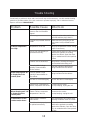
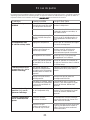
Trouble Shooting
Problem Possible Cause What to do
No Power
A fuse in your home may
Replace fuse or reset circuit breaker.be
blown or the circuit
Plug not fully inserted into
wall
outlet
Door(s) not shut properly Ensure that the doors are fully closed
only as needed and for short periods
Exhaust vent is obstructed Verify there is nothing blocking the
Recently
added
a
large
Limit the quantity of warm items
Condensation on the
High humidity conditions The condensation will subside once
Door(s) not shut properly Ensure that the doors are fully closed
against the cabinets. Open the doors
only as needed and for short periods
breaker
tripped
Power surge
too
High
or
opened excessively
and that the gaskets are sealing
against the cabinet. Open the doors
the
cabinet
of time
cabinet and/or doors
in the home humidity conditions return to normal
quantity
of
warm
bottles to
being introduced to the cabinet.
front mounted exhausting vent
of time
Adjust if neccessary
Cabinet
Temperature Temperature
Verify the temperature control setting
or opened excessively
and that the gaskets are sealing
Alarm Beeping and “HI”
is displayed on the
control panel
not as set
Recently added a large
to the cabinet
quantity
of warm bottles
Limit the quantity warm items
being introduced to the cabinet.
of
The door is not closed tightly Be sure the door is closed tightly
System leak, evaporator fan
failure, compressor fan failure
Contact service center.
To stop beeping, unplug the unit
Alarm Beeping and “LO”
is displayed on the
control panel
Sensor Failure, evaporator
temperature is too low
Contact service center.
To stop beeping, unplug the unit
Unplug the wine cooler, wait a few
seconds and then plug it back in
Make sure the 3-prong plug on the
wine cooler is fully inserted into the
outlet
Occasionally, a problem is minor and a service call may not be necessary - use this trouble shooting
guide for a possible solution. If the unit continues to operate improperly, call an authorized service
depot or toll free at 1-844-455-6097

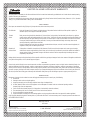
LIMITED IN-HOME APPLIANCE WARRANTY
This quality product is warranted to be free from manufacturer’s defects in material and workmanship, provided that the unit is used under the normal operating
conditions intended by the manufacturer.
This warranty is available only to the person to whom the unit was originally sold by Danby Products Limited (Canada) or Danby Products Inc. (U.S.A.) (hereafter
“Danby”) or by an authorized distributor of Danby, and is non-transferable.
TERMS OF WARRANTY
Plastic parts, are warranted for thirty (30) days only from purchase date, with no extensions provided.
First 24 Months
During the first twenty four (24) months, any functional parts of this product found to be defective, will be repaired or replaced, at
warrantor’s option, at no charge to the ORIGINAL purchaser.
To obtain
Danby reserves the right to limit the boundaries of “In Home Service” to the proximity of an Authorized Service Depot. Any appliance
Service
requiring service outside the limited boundaries of “In Home Service” ,it will be the consumer’s responsibility to transport the appliance (at
their own expense) to the original retailer (point of purchase) or a service depot for repair. See “Boundaries of In Home Service” below.
Contact your dealer from whom your unit was purchased, or contact your nearest authorized Danby service depot, where service
must be performed by a qualified service technician.
If service is performed on the unit by anyone other than an authorized service depot, or the unit is used for commercial application, all
obligations of Danby under this warranty shall be void.
Boundaries of
If the appliance is installed in a location that is 100 kilometers (62 miles) or more from the nearest service center your unit must be
In Home Service
delivered to the nearest authorized Danby Service Depot, as service must only be performed by a technician qualified and certified for
warranty service by Danby. Transportation charges to and from the service location are not protected by this warranty and are the
responsibility of the purchaser.
Nothing within this warranty shall imply that Danby will be responsible or liable for any spoilage or damage to food or other contents of this appliance, whether due
to any defect of the appliance, or its use, whether proper or improper.
EXCLUSIONS
Save as herein provided, Danby, there are no other warranties, conditions, representations or guarantees, express or implied, made or intended by Danby or its
authorized distributors and all other warranties, conditions, representations or guarantees, including any warranties, conditions, representations or guarantees
under any Sale of Goods Act or like legislation or statue is hereby expressly excluded. Save as herein provided, Danby shall not be responsible for any damages
to persons or property, including the unit itself, howsoever caused or any consequential damages arising from the malfunction of the unit and by the purchase of
the unit, the purchaser does hereby agree to indemnify and hold harmless Danby from any claim for damages to persons or property caused by the unit.
GENERAL PROVISIONS
No warranty or insurance herein contained or set out shall apply when damage or repair is caused by any of the following:
1) Power failure.
2) Damage in transit or when moving the appliance.
3) Improper power supply such as low voltage, defective house wiring or inadequate fuses.
4) Accident, alteration, abuse or misuse of the appliance such as inadequate air circulation in the room or abnormal operating conditions
(extremely high or low room temperature).
5) Use for commercial or industrial purposes (ie. If the appliance is not installed in a domestic residence).
6) Fire, water damage, theft, war, riot, hostility, acts of God such as hurricanes, floods etc.
7) Service calls resulting in customer education.
8) Improper Installation (ie. Building-in of a free standing appliance or using an appliance outdoors that is not approved for outdoor application).
Proof of purchase date will be required for warranty claims; so, please retain bills of sale. In the event warranty service is required, present this document to our
AUTHORIZED SERVICE DEPOT.
Danby Products Limited
PO Box 1778, Guelph, Ontario, Canada N1H 6Z9
Telephone: (519) 837-0920 FAX: (519) 837-0449
Danby Products Inc.
PO Box 669, Findlay, Ohio, U.S.A. 45840
Telephone: (419) 425-8627 FAX: (419) 425-8629
04/09
1-844-455-6097
Warranty Service
In-home

Informations de sécurité importantes
Précautions 15
Instructions de mise à la terre 16
Instructions de fonctionnement
Caractéristiques de votre refroidisseur de vin
17
Commandes de votre refroidisseur de vin
18
R
églage de la température
18
Instruction de fonction 18
Entreposage des vins 19
Instruction des tabletts 19
Instructions d'installation
Outils néccesaires 20
Préparation de l’enceinte 20
Renversement de la Porte 21
Soin et nettoyage
Conseils utiles 22
Comment nettoyer l’intérieur 22
Comment nettoyer l’extérieur 22
En cas de panne
Avant de placer un appel de service 23
Garantie 24
15
17
22
23
12
TABLE DES MATIÈRES
20

13
BIENVENUE
EN CAS DE BESOIN
D’ASSISTANCE
Bienvenue dans la famille
Danby. Nous sommes
fiers de nos produits de
qualité et croyons au bien
fondé de fournir une
assistance fiable à nos
clients.
Vous le découvrirez par
ce guide facile d’utilisation
et vous pourrez l’entendre
en provenance des voix
amicales de notre service
d’assistance à la clientèle.
Tél.: 1-844-455-6097
Mais, ce qui est encore
mieux, vous pourrez
bénéficier de ces valeurs
à chaque utilisation de
votre refroidisseur de vin.
Ceci est important parce
que votre nouvelle
appareil fera partie de
votre famille pour
longtemps.
Voici quelques contributions
que vous pouvez effectuer
avant de faire un appel de
service, pour nous aider à
mieux vous servir :
Lisez ce guide
Il comprend des instructions
pour vous assister à l’utilisa-
tion et l’entretien adéquats de
votre refroidisseur de vin.
Si votre appareil neuf est
avarié
Communiquez immédiatement
avec le revendeur (ou le man-
ufacturier).
Épargnez temps et argents
Avant de faire un appel de
service, révisez le chapitre
intitulé “Dépannage”. Ce
chapitre vous aidera à solu-
tionner des problèmes com-
muns qui pourraient survenir.
Si une réparation est requise,
vous pouvez avoir l’esprit tran-
quille parce que de l’aide ne
sera l’affaire que d’un appel
téléphonique.
Tél.: 1-844-455-6097
Enregistrez ici les numéros de modèle
et de série. Ces numéros se trouvent
sur l’étiquette au dos de l’appareil.
Numéro de modèle: DWC140D1BSSPR
Numéro de série:
Date d’achat:
Agrafez votre reçu d’achat à l’intérieur
de la couverture arrière de de guide. Il
sera requis pour faire une réclamation
de la garantie.
Point de départ...AVANT d’utiliser votre cabinet à vin

LISEZ TOUTES LES INFORMATIONS DE SÉCURITÉ
AVANT DE FAIRE FONCTIONNER L’APPAREIL
14
INFORMATIONS DE SÉCURITÉ IMPORTANTES
AVERTISSEMENT
PRÉCAUTIONS
Pour minimiser le risque d’incendie, de brûlures, de chocs électriques ou de blessures,
suivez les chapitres suivants en plus d’appliquer les précautions de base.
Cet appareil doit être mis à lat-
terre. Branchez le seulement dans
une prise correctement mise à la
terre. Référez-vous au chapitre intit-
ulé “Instructions de mise à la terre” à
la page 16.
Ne faites pas fonctionner cet
appareil s’il a un cordon ou fiche
électrique endommagé, s’il ne fonc-
tionne pas correctement, ou si
l’appareil a été endommagé ou
échappé.
N'épissez pas le cordon électrique
Gardez le cordon électrique
éloigné des sources de chaleur.
N’immersez pas le cordon ou sa
fiche dans aucun liquide.
N’utilisez pas cet appareil près de
bassins d’eau, par exemple dans un
sous-sol détrempé, près d’une
piscine ou d’un évier.
N’utilisez pas de produits
chimiques ou vapeurs corrosives
dans/près de cet appareil.
N’utilisez cet appareil que pour
les fins auxquelles il est conçu
comme indiqué dans ce guide.
Ne placez pas les articles périss-
ables de nourriture dans votre
refroidisseur de vine. (Pour exam-
plem, les viandes et les produits
laitiers)
Entreposez le vin dans des
bouteilles scellées seullement.
Référez-vous aux instructions de
nettoyage du fini de la porte se trou-
vant au(x) chapitre(s) de Soins et
nettoyage de ce guide.
Ne recouvrez pas ou n’obstruez
aucune ouverture de l’appareil.
Cet appareirl est conçu pour un
usage domestique à l’intérieur
seulement. N’entreposez ni n’u-
tilisez pas cet appareil à l’extérieur.
Cet appareil ne devrait être réparé
que par du personnel qualifié. Pour
tout examen, réparation ou réglage,
contactez votre centre de service le
plus rapproché.
SAUVEGARDEZ CES INSTRUCTIONS
DANGER, RISQUE DES ENFANTS DEVIENNENT COINCER DANS L’APPAREIL
Un refroidisseur de vin vide est une attraction dangereuse aux enfants. Enlever les joints étanch-
es, les loquets, les couvercles ou les porte des appareils qui ne sont pas utiliser, ou faites de soit
que l’appareil ne présente aucun danger.
N’ATTENDEZ PAS! FAITES-LE IMMEDIATEMEN!

15
Cet appareil doit être mis à la
terre. Dans l’éventualité d’un
court-circuit, la mise à la terre
procure un chemin direct de
contournement du courant
pour prévenir l’électrocution
des manipulateurs de l’ap-
pareil.
Cet appareil est muni d’un cor-
don comprenant une fiche et
fil de mise à la terre.
La fiche doit être branchée
dans une prise correctement
installée et mise à la terre.
Si les directives de mise à la
terre ne sont pas tout à fait
comprises ou en cas de tout
doute relatif à la mise à la
terre appropriée de l’appareil,
faites appel à un électricien ou
à un technicien qualifié.
Si la prise murale est une
prise à 2 branches, c’est votre
obligation, et la responsabilité
vous en incombe, de la faire
remplacer par une prise à trois
branches adéquatement mise
à la terre.
Pour un meilleur rendement et
pour éviter que les ampoules
d’éclairage de la résidence
soient affectées d’un affaisse-
ment de tension, ou que le
fusible ou disjoncteur du circuit
ne grille ou ne se déclenche,
dédiez un circuit individuel
d’alimentation à la machine à
glaçons (prise (double) unique
sur le circuit).
Sous aucun prétexte il est
permis de couper ou d’enlever
la troisième branche (mise à la
terre) de la fiche du cordon
électrique.
N’utilisez pas d’adaptateur
de fiche avec cet appareil.
N’utilisez pas de cordon de
rallonge avec cet appareil. Si
le cordon électrique de l’ap-
pareil ne rejoint pas la prise
murale, faites installer une
prise plus rapprochée par un
électricien ou un technicien
qualifié.
INSTRUCTIONS
DE MISE À LA
TERRE
INFORMATIONS DE SÉCURITÉ IMPORTANTES
AVERTISSEMENT
Une mauvaise utilisation
de la mise à la terre de la
fiche constitue un danger
d’électrocution.
AVERTISSEMENT!
Danger de poids excessif
Il faut deux personnes ou plus
pour déplacer le refroidisseur de
vin.
Sous le conduit de ventilation
du refroidisseur de vin, deux
pattes de réglage de niveau
sont situées sur chaque côté du
conduit de ventilation. Il est
important que votre refroidis-
seur de vin soit à niveau.
1. Installez le refroidisseur de
vin à sa position finale.
2. Demandez à une autre
personne d’appliquer une
légère pression sur la
partie avant supérieure du
refroidisseur de vin pour
l’incliner et alléger la
pesanteur sur les pattes de
réglage de mise à niveau.
3. Pivotez les pattes de mise à
niveau dans le sens des
aiguilles d’une montre pour
lever le refroidisseur à vin ou
dans le sens contraire pour
l’abaisser. Continuez le
procédé jusqu’à ce que le
refroidisseur soit à niveau.
Voir la Fig. A.
Instructions de
mise à niveau
Fig. A
d'élever
la patte
(abaisser
l'unité)
(lever l'unité)
Abaissez
la patte
Pour mettre le refroidisseur
de vin à niveau :

16
Instructions de fonctionnement
Caractéristiques de votre
refroidisseur de vin
8
6
1
5
2
7
3
4
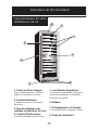
1. Portes en Verre Trempé:
Verre à faible émissivité - Utillsé à
réfléchir et à bsorber la chaleur.
2. Lumière Intérieures:
S’aIllume lorsqu’on ouvre la porte
du cabinet.
3. Bois-des étagères avec
roulettes inoxversions en acier.
4. Controls Électroniques:
Contrôlede latempérature de l'unité
5. Joint Étanche Magnétique:
Le jointétanche permet de conserver le
niveau de température et d’humidité
àl’intérieur du cabinet.
6. Poignée
7. Échappement sur le Devant:
Pour desapplications intégrées cabinet.
8. Pieds de nivellement

Pour changer l'affichage entre
la température en Celsius (°C)
et la la température en
Fahrenheit (°F) appuyez sur les
bouton de control et
en même temps pour environ
5 secondes.
compartiments peut être ajustée
aussi basse que 39°F(4°C) ou
aussi haut que 64°F (18°C) pour
saisfaire à vos besoin spécifiques
pour votre entreposage de vin.
Chaque pression du bouton
commande ou vous per-
mettra d'ajuster la température par
intervalle de un degré dans la
marge mentionnée ci-dessus.
˚
˚
˚
˚
6
7
Instructions de fonctionnement
Commandes de votre
refroidisseur de vin
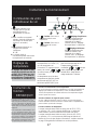
1. Le voyant s’allume pour
indiquer que le cycle de
refroidissement est
presentment en marche.
2. Pour contrôler cet appareil
allumer / éteindre (Appuyez et
maintenez ces bouton pour
environ 3 secondes).
3. Manuellement illuminer ou
éteignez les lumières
intérieures.
C° / F°
4. Le voyant situés à
côté, dénote quelle balance de
la température est montrée.
5. ‘ ’ Fenêtre :Pour vue la
température de la zone
supérieure.
6. ‘ ’ Fenêtre: Pour vue la
température de la zone
inférieure.
7. ‘ ’ Réglage Supérieure :
Réglez la température du
chambre supérieure par
intervalle de un degré
(référez-vous au “Réglage
du température” ci-dessous).
‘ ’Réglage Inférieure :
Réglez la température du
chambre inférieure par
intervalle de un degré
(référez vous au “Réglage
du température” ci-dessous).
R
é
glage du
temp
é
rature
17
Le réglage par défaut du ther-
mostat du refroidisseur de vin
est 54°F (12°C) dans les com-
partiment. 45°F (7°C) dans la
zone inférieure, Température
est affichée en Fahrenheit (°F)
Instruction de
fonction
REMARQUE!
Si trop de bouteilles de vin sont mises dans
le refroidisseur en même temps ou si la
porte n’est pas bien fermée, il est possible
que « HI » apparaisse sur l’afficheur. C’est
un phénomène normal : attendez quelques
minutes après avoir fermé la porte et « HI »
disparaîtra.
Il est normal que le cabinet indique « HI »
ou « LO » de temps à autre. Si cela se pro-
duit fréquemment ou dure longtemps, vous
pouvez éteindre l’appareil, puis le rallumer,
pour corriger la situation. Si le problème se
reproduit après le redémarrage de l’ap-
pareil, veuillez communiquer avec le serv-
ice après-vente pour obtenir de l’aide.
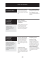
Fonction de mémorisation de la température
En cas de panne de courant, le refroidisseur à vin peut sauvegarder les
réglages précédents de la température, et lors du rétablissement du
courant, la température du cabinet retournera à la température réglée
avant la panne de courant.
Fonction d’alarme de rappel de porte ouverte
Si vous oubliez de fermer la porte ou celle-ci n’est pas bien fermée,
l’alarme retentit au bout de 5 minutes. Veuillez fermer complètement la
porte et éviter que le froid s’échappe.
Fonction d’alarme
de température
La température pour les deux
Lorsque la température intérieure est à plus de 23°C (73°F),
on peut lire « HI » sur le panneau d’affichage, ou advenant
cette situation, l’alarme se déclenchera après une heure.
Lorsque la température intérieure est à moins de 0°C (32°F),
on peut lire « LO » sur le panneau d’affichage et l’alarme se
déclenche. Pour de plus amples informations, veuillez consulter
la page 23 du guide de l’utilisateur en cas de problèmes.

18
!TNATROPMI
E.giF
D.giF
C.giF
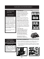
IMPORTANT!
1. The upper zone
In order to achieve a maximum
capacity of 60 bottles the bottles
must be positioned alternately on
the upper six (6) shelves as shown
in Fig. D. This will allow for the
storage of 10 bottles per shelf on
each of the 6 shelves in this
chamber.
2. The lower zone
In order to achieve the maximum
capacity of 80 bottles,it will be
necessary to position the bottles
alternately on the upper six(6)
shelves,as shown in Fig.D. This
will allow for the storage of ten
(10) 750ml bottles per shelf on
each of the lower six (6) shelves.
On the bottom of cabinet
holds fifteen (15) 750ml bottles
when stocked according to Fig.E.
G .giFF .giF
The maximum capacity of the
DWC140D1BSSPR is 135
bottles.The upper zone will
hold a maximum of 60 bottles
and the lower zone a maximum
of 75 bottles. These capacities
are based on a standard 750ml
Bordeaux style bottles that are
3” in diameter. The actual
capacity will be dictated by the
size and shape of the bottles
and may be reduced depending
on these variables.
Only store unopened, sealed
bottles in the unit.
Alternatively, the spacing between
shelves is greater in the upper zone
and allows for the storage of larger
diameter bottles such as Pinot and
Burgundy with diameters up to 3 5/8”.
In order to achieve the optimum stor-
age, the bottles should be positioned
alternately on the upper six shelves
as shown in Fig. C. This will allow for
the storage of up to 9 bottles per shelf
for a reduced capacity of 54 bottles in
this zone.
Pour retirer les clayettes à vin :
1. Étirer complètement la clayette que vous désirez retirer (Fig. F)
2. Soulever vers le haut la partie avant de la clayette (Fig. F)
3. Tout en maintenant le rebord de la clayette, pousser la clayette
en place et puis vers le haut de manière à la libérer des clapets
arrières. (Fig. G)
SAP zervuocer eN sel
-ula’d selliuef ed serègaté
ertua tuot ed uo muinim
tiardneivérp iuq enarbmem
-ni’l
à ria’l ed noitalucric al
.tenibac ud rueirét
Instructions
pour tablettes
Entreposage
des vins
Instructions de fonctionnement

19
Instructions d’installation - Application Intégré
Préparation de l’enceinte
Outils néccesaires
Fig.F
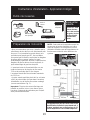
NOTE: Cette unité est la respiration avant. Ne
bloquez pas la bouche d'aération sur la face
avant de l'appareil. Le blocage de la bouche
d'aération se traduira par des températures de
fonctionnement élevées et de défaillance du
système.
Ruban à
mesurer
Equerre de
charpentier
Perceuse et jeu de
scie cylindrique
Gants
Niveau
Lunette de sécurité
Lampe de poche
En faire les insta-
llations décrites
dans cette section,
des gants, les lun-
ette de sûcurité
devraient être
portés.
POUR VOTRE
SÛRETÉ:
de
sérer
moire
trou
ou
mc6.571
mc72.9
sèccA
:euqirtcelÉ
mc18.3
erreuqÉ
eriomrA
te
eirebmolp
60.1cm
L’ouverture brute de l’armoiredoit être sur une
surface niveau avec le plancher et d’au moins
72.9 cm de profonder par 60,1cm largeur.
L’ouverture devrait être à une hauteur maximale
de 176.5 cm.
La prise murale peut être placé de l'un ou l'autre
côté si la prise murale n'est pas dans l'ouverture
d'installation, ou de l'arrière du secteur ombragé
(comme montré dans Fig. C.).
Important :Si la prise de courant électrique est
installée en surface (et non à ras dumur) dans
l’enceinte, l’exigence de profondeur pour l’install-
ation pourrait être affectée.
Nous recommandons que vous n'installez pas le
refroidisseur de vin dans un coin (directement près
d'un mur). Ceci permettre les portes d'avoir une
oscillation plus grande que 90°. Une oscillation
d’ouverture qui est limitée, empêchera les étagères
de glisser dehors comme supposé, et peut
endommager la garniture de porte., empêchera les
étagères de glisser dehors comme supposé, et
peut endommager la garniture de porte.
Cet appareil doit être raccordé à un circuit
de dérivation indivdual correctment mis à
la terre, protégér par un disjoncteur de 15
ou 20 ampères ou d’un fusible temporisé.
Alimentation:
La page est en cours de chargement...
La page est en cours de chargement...
La page est en cours de chargement...
La page est en cours de chargement...
-
 1
1
-
 2
2
-
 3
3
-
 4
4
-
 5
5
-
 6
6
-
 7
7
-
 8
8
-
 9
9
-
 10
10
-
 11
11
-
 12
12
-
 13
13
-
 14
14
-
 15
15
-
 16
16
-
 17
17
-
 18
18
-
 19
19
-
 20
20
-
 21
21
-
 22
22
-
 23
23
-
 24
24


Danby DWC140D1BSSPR Le manuel du propriétaire
- Catégorie
- Cave à vin
- Taper
- Le manuel du propriétaire
dans d''autres langues
- English: Danby DWC140D1BSSPR Owner's manual
Documents connexes
-
Danby DWC031D1BSSPR Le manuel du propriétaire
-
-
-
-
-
-
-
Danby DWC031D1BSSPR Tuscany Le manuel du propriétaire
-
-
Silhouette SSWC056D1BS Le manuel du propriétaire