
MD 052B7150
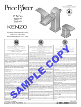
MOUNTING SOLUTIONS
5
YEAR
VES A
120kg
PRODUCT MANUAL
DE Produkthandbuch
FR Manuel de produit
NL Producthandleiding
9
8
7
6
3
2
Instructions reset controlbox
CONTENTS
Mounting regulations
Specification sheet
Mounting instructions
User manual
Wiring diagram

MD 052B7150
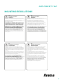
MOUNTING REGULATIONS
Correcte montage is van absoluut belang en valt niet binnen
de aansprakelijkheid van SmartMetals Mounting Solutions.
Onjuiste montage kan tot persoonlijk letsel en materiële schade
leiden. SmartMetals kan niet op wat voor manier dan ook
aansprakelijk worden gesteld indien dit product op onjuiste wijze
is gemonteerd.
Om veiligheidsredenen wordt geen montagemateriaal
bijgevoegd, gezien het feit dat de staat en het draagvermogen
van plafonds/muren individueel zijn. Montagemateriaal kan
worden gekozen al naar gelang het materiaal van plafond/
muur.
Raadpleeg een vakspecialist voor de keus van geschikt
montagemateriaal. De installateur moet vaststellen of het
plafond/de muur minstens vier keer van het gecombineerde
gewicht van scherm/projector en steun kan dragen. Maximale
belasting voor dit product volgens de informatie in deze
montagevoorschriften. Voor de montage moeten ook de
installatie- en gebruiksvoorschriften voor het te monteren
scherm/projector in acht worden genomen.
NL
Montage voorschriften
WAARSCHUWING
Le montage doit impérativement être effectué de façon
correcte et ne relève pas de la responsabilité de SmartMetals
Mounting Solutions. Un mauvais montage peut occasionner des
blessures corporelles et des dommages matériels. SmartMetals
décline toute responsabilité en cas de montage incorrect de
ses produits.
Pour des raisons de sécurité, aucun matériel de montage n’est
livré avec les produits, car la nature et la capacité de soutien
des murs/plafonds varient. Le matériel de montage est choisi en
fonction de la composition du mur/plafond.
Pour vous aider à choisir le bon matériel, consultez un expert
responsabilité de l’installateur de veiller à ce que le mur/plafond
puisse supporter au moins quatre fois le poids total de l’écran/
vidéo-projecteur et de son support. Charge max. pour ce
produit, d’après l’information dans ce guide d’installation. Lors
du montage, les instructions d’installation et d’utilisation de
l’écran/vidéo-projecteur doivent elles aussi être suivies.
FR
Règlements de montage
AVERTISSEMENT
A correct mounting is extremely important and this is not the
responsibility of SmartMetals Mounting Solutions. Faulty mounting
may result in injury to persons or damage to equipment.
SmartMetals will not be responsible in any way if the product has
been mounted incorrectly.
of safety, since the properties and bearing strength of walls/
must be selected based on the material of the wall/ceiling.
responsibility of the installer to ensure that the wall/ceiling
can support at least four times the combined weight of the
screen/projector and bracket. The maximum load for this
product is given in these mounting instructions. The instructions
for installation and use of the screen/projector must also be
followed with respect to the location and attachment of the
screen/projector.
GB
Mounting regulations
WARNING
Eine korrekte Montage ist von größter Bedeutung, und
SmartMetals Mounting Solutions kann dafür keine Verantwortung
übernehmen. Falsche Montage kann zu Personen- und
Sachschaden führen. SmartMetals lehnt jede Art von
Verantwortung ab, falls das Produkt falsch montiert wird.
Aus Sicherheitsgründen wird kein Montagematerial beigefügt,
da Beschaffenheit und Tragkraft von Wand bzw. Decke
unterschiedlich sind. Das Material für die Montage richtet sich
nach dem Material von Wand bzw. Decke.
Bei der Wahl des geeigneten Montagematerials sollten Expertise
trägt die Verantwortung dafür, dass die Wand bzw. Decke
mindestens das vierfache Gesamtgewicht von Bildschirm/
Projektor plus Halterung tragen kann. Maximale Belastung
für dieses Produkt steht in dieser Montageanleitung. Bei der
für den anzubringenden Bildschirm/Projektor beachtet werden.
DE
Montagevorschriften
WARNUNG
2

MD 052B7150
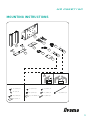
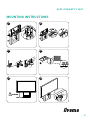
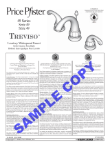
MOUNTING INSTRUCTIONS
1
2
3
4
5
6
7
8
11
9
MON.0095
MON.0120
10
MON.0095
10a | M6x16 | 8x
10b | M6 | 8x
10c | M6x25 | 8x
10d | 25x45 | 1x
MON.0120
11a | M6x12 | 4x
11b | M6x25 | 4x
11c | D25, d8.4x30 | 4x
11d | M8x14 | 4x
11e | M8x25 | 4x
11f | M8x45 | 4x
11g | 200x3.6 | 2x
3

MD 052B7150
3
5
4
1 2
6
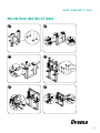
MOUNTING INSTRUCTIONS
4
2
1
2
1
B
3
2.1
2.2
3
2.1
2.2
4
4
2
1
4
4
3
3
6
7
7
5
10b | 8x
10c | 8x
max 10 Nm

MD 052B7150
9
11
10
7 8
12
MOUNTING INSTRUCTIONS
7.1
7.2
8
10
052.7135
3
3
10
052.7135
Max 120 kg (265 lbs)
11a - 11b 11d - 11e | 4x
Optional | 11f | 4x
Optional | 11c | 4x
10d
5
11g
11g
8
3
8
08.1
08.208.2
10
min. 4 mm
8
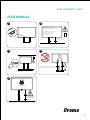
Kg

Max 120 Kg
product only under supervision of an adult
Children older than six years, may use the
under the lift system
Do not place objects
SE Varning! Klämrisk
PL Uwaga! Ryzyko przygniecenia
NL Voorzichtig! Beknellingsgevaar
IT Attenzione! Rischio di schiacciamento
GB Caution! Risk of crushing
FR Attention! Risque d'écrasement
FI Varoitus! Puristumisvaara
ES ¡Precaución! Peligro de aplastamiento
DK Forsigtig! Fare for knusning
DE Achtung! Risiko des Zerquetschens
MD 052B7150
120 Kg
on product
Max weight
3
5
4
USER MANUAL
Up
Down
1 2
6
Kg

MD 052B7150
3
5
4
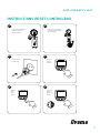
INSTRUCTIONS RESET CONTROLBOX
1 2
6
Push the
down
button for
30 sec
30s
Release
the
down
button
Move to
lowest
position
power plug
Connect the
the controlbox
from the power plug to
Check the connection
the controlbox
from the remote to
Check the connection
7

MD 052B7150
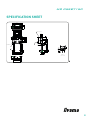
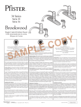
SPECIFICATION SHEET
AA
145
620
145
420
232.5
680
100
200
400
440
600
200
300
400
100
227.5
265
37
300
580
250
75
125
75
90400
112.5
+5
-75
635 - 655
125
213
103
936 - 1806
stroke = 870
25
8.5
127.5 392.5 127.5
677.5
147
8.5
6.5
11
11
SmartMetals
Mounting Solutions BV
Vlietskade 8016
4241 WS Arkel
The Netherlands
www.smartmetals.nl
Product: Floor supp. wall lift XXL for touch screen 86 inch, 120 kg
A4
Product code: 052-7150W Maximum load: 120 kg Net weight: 34 kg Rev.: B Units: mm
M4 (4x)
SEE DETAIL A
max free space
center of screen
max free space
SECTION A-A
DETAIL A
SCALE 0.150
8

MD 052B7150
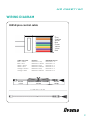
WIRING DIAGRAM
Cable wire color Function RJ45 8 Pin plug no.
Blue + Green Reference 1 Up RJ45 Pin 4 + 5
Blue + Red Reference 1 Down RJ45 Pin 4 + 8
White + Green Reference 2 Up RJ45 Pin 3 + 5
White + Red Reference 2 Down RJ45 Pin 3 + 8
Orange + Green Reference 3 Up RJ45 Pin 2 + 5
Orange + Red Reference 3 Down RJ45 Pin 2 + 8
L = 1700 mm +/- 70 mm
70 - 20
150
+/- 20
70
+/- 20
RJ45 8 pins control cable
+/ +/ +/
70+/-20
150+/-20
70+/-20
Grey
Orange
White
Blue
Green
Yellow
Violet
Red
9
-
 1
1
-
 2
2
-
 3
3
-
 4
4
-
 5
5
-
 6
6
-
 7
7
-
 8
8
-
 9
9


iiyama MD 052W7150K Manuel utilisateur
- Taper
- Manuel utilisateur
- Ce manuel convient également à
dans d''autres langues
- English: iiyama MD 052W7150K User manual
- Deutsch: iiyama MD 052W7150K Benutzerhandbuch
- Nederlands: iiyama MD 052W7150K Handleiding
Documents connexes
Autres documents
-
AG Neovo FMC-05B Manuel utilisateur
-
-
 Pfister F-049-ST0K Guide d'installation
-
 Pfister GT49YP1K Guide d'installation
-
 Pfister F-049-LT0Y Guide d'installation
-
 Pfister GT49DF0C Guide d'installation
-
 Pfister F-049-DK00 Guide d'installation
-
 Pfister LF-034-3ALY Guide d'installation


