La page est en cours de chargement...
La page est en cours de chargement...
La page est en cours de chargement...

Page 4
AG Neovo Technology B.V. • Molenbaan 9 • 2908 LL CAPELLE A/D IJSSEL • The Netherlands
FWL-01B
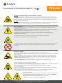
INFORMATIONS DE SÉCURITÉ IMPORTANTES - FR
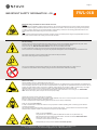
Informations de sécurité importantes pour l’installateur et l’utilisateur
l’Installateur:
Avant de commencer l’installation, lisez attentivement les consignes de sécurité, les réglementations de montage et le reste
de ce manuel du produit. Si vous ne lisez pas, ne comprenez pas bien et ne suivez pas toutes les instructions, vous risquez
de vous blesser gravement, d’endommager l’équipement ou d’annuler la garantie d’usine! Il est de la responsabilité de
l’installateur certié de s’assurer que tous les systèmes / accessoires de montage sont correctement assemblés et installés en
utilisant les instructions fournies.
l’Utilisateu:
Veuillez lire attentivement les informations de sécurité ci-dessous et le manuel d’utilisation (le cas échéant) avant d’utiliser le
support ou le support sur roulettes à hauteur réglable. Cela garantit une unité sans défaillance et évite les accidents.
Sécurité électrique
Connectez l’appareil à une prise correctement mise à la terre uniquement. Assurez-vous que l’appareil peut être
immédiatement séparé de la prise de courant.
N’utilisez l’appareil que dans des pièces sèches, protégez-le de l’eau et d’autres liquides. Essuyez uniquement l’appareil avec
un chion sec.
N’ouvrez pas l’unité de levage. RISQUE DE CHOC ELECTRIQUE. Il n’y a aucune pièce réparable à l’intérieur.
En cas de dysfonctionnement, débranchez l’unité de la prise de courant et appelez un technicien agréé.
Ne surchargez pas le cordon d’alimentation et ne l’endommagez d’aucune autre manière. Remplacez immédiatement les
cordons endommagés par de nouveaux câbles identiques.
Les connexions des prises de l’appareil et de la prise murale doivent être facilement accessibles.
Débranchez la che secteur avant de déplacer le produit.
L’appareil n’est pas protégé contre les gouttes d’eau ou les éclaboussures. Ne placez pas d’objets remplis de liquide sur
l’appareil et ne le vaporisez pas.
Pour réduire le risque de choc électrique: Débranchez toujours l’appareil de la prise électrique avant de le nettoyer.
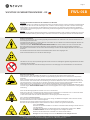
Sécurité mécanique
Assurez l’installation de l’unité uniquement par un technicien agréé.
Utilisez uniquement les pièces de montage d’origine fournies avec le système et n’utilisez pas d’accessoires non recommandés
par le fabricant.
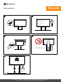
Ne chargez pas l’unité de manière incorrecte: Pour le max. charge de l’unité, veuillez vous référer à la page avec la che
technique de ce manuel. Ne pas dépasser: une utilisation avec des écrans plus lourds peut entraîner une instabilité provoquant
le basculement, entraînant la mort ou des blessures graves! La fonction de réglage en hauteur de cet appareil ne fonctionnera
pas correctement si le poids dépasse la charge maximale donnée.
N’utilisez ce système de montage que pour l’usage auquel il est destiné, comme décrit dans ces instructions. Ne vous
accrochez pas à l’appareil. UNITÉ TRÈS LOURDE. Risque de blessure grave lorsque l’appareil bascule en raison d’une
mauvaise utilisation.
Gardez toujours la trajectoire de mouvement du produit libre d’obstacles.
Avant de déplacer l’unité vers le haut ou vers le bas, assurez-vous au moins une distance de sécurité de 20 cm / 7,9 pouces
de toute partie de l’unité à tout autre accessoire an d’éviter les pièges de cisaillement ou les points de serrage.
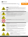
En cas d’accident, veuillez libérer le panneau de commande. Le mouvement de l’unité s’arrêtera immédiatement.
Votre unité a-t-elle un anti-collision?
En cas d’accident avec un lift avec anti-collision, il est très important de libérer le panneau de commande: continuer à pousser
entraîne une neutralisation de l’anti-collision!
Tenez également compte du fait que l’anti-collision ne fonctionne qu’après env. 1 seconde après l’activation du lift.
Veuillez lire le chapitre séparé de ce manuel sur ce sujet pour son fonctionnement exact.
Votre appareil est-il équipé de roulettes?
N’utilisez l’unité sur roulettes que sur des sols plats et stables. Déplacer l’unité uniquement sur les
planchers plats.
Risque de basculement lors des planchers inégalités, seuils de porte et similaires. UNITÉ TRÈS
LOURDE. Risque de blessure grave lorsque l’unité bascule.
Bloquer les freins des roues avant lors de l’utilisation de l’unité.
Déplacez toujours votre trolley avec l’écran en position la plus basse.
1
2
La page est en cours de chargement...

Page 6
AG Neovo Technology B.V. • Molenbaan 9 • 2908 LL CAPELLE A/D IJSSEL • The Netherlands
FWL-01B
A correct mounting is extremely important and this is not the responsibility of SmartMetals
Mounting Solutions. Faulty mounting may result in injury to persons or damage to equipment.
SmartMetals will not be responsible in any way if the product has been mounted incorrectly.
Mounting ttings are not included with the product for reasons of safety, since the properties
and bearing strength of walls/ceilings are specic for each case. Suitable mounting ttings
must be selected based on the material of the wall/ceiling.
Obtain advice from a specialist in the eld or from a specialist shop concerning the choice
of mounting ttings. It is the responsibility of the installer to ensure that the wall/ceiling
can support at least four times the combined weight of the screen/projector and bracket.
The maximum load for this product is given in these mounting instructions. The
instructions for installation and use of the screen/projector must also be followed with respect
to the location and attachment of the screen/projector.
GB
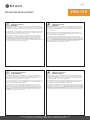
Mounting regulations
WARNING
Eine korrekte Montage ist von größter Bedeutung, und SmartMetals Mounting Solutions
kann dafür keine Verantwortung übernehmen. Falsche Montage kann zu Personen- und
Sachschaden führen. SmartMetals lehnt jede Art von Verantwortung ab, falls das Produkt
falsch montiert wird.
Aus Sicherheitsgründen wird kein Montagematerial beigefügt, da Beschaenheit und
Tragkraft von Wand bzw. Decke unterschiedlich sind. Das Material für die Montage richtet
sich nach dem Material von Wand bzw. Decke.
Bei der Wahl des geeigneten Montagematerials sollten Expertise oder Fachhandel
herangezogen werden. Der Installateur trägt die Verantwortung dafür, dass die Wand bzw.
Decke mindestens das vierfache Gesamtgewicht von Bildschirm/Projektor plus Halterung
tragen kann. Maximale Belastung für dieses Produkt steht in dieser Montageanleitung.
Bei der Montage müssen auch Installations- und Benutzungsvorschriften für den
anzubringenden Bildschirm/Projektor beachtet werden.
DE
Montagevorschriften
WARNUNG
Le montage doit impérativement être eectué de façon correcte et ne relève pas de la
responsabilité de SmartMetals Mounting Solutions. Un mauvais montage peut occasionner
des blessures corporelles et des dommages matériels. SmartMetals décline toute
responsabilité en cas de montage incorrect de ses produits.
Pour des raisons de sécurité, aucun matériel de montage n’est livré avec les produits, car
la nature et la capacité de soutien des murs/plafonds varient. Le matériel de montage est
choisi en fonction de la composition du mur/plafond.
Pour vous aider à choisir le bon matériel, consultez un expert dans ce domaine ou un
magasin spécialisé. Il est de la responsabilité de l’installateur de veiller à ce que le mur/
plafond puisse supporter au moins quatre fois le poids total de l’écran/vidéo-projecteur et
de son support. Charge max. pour ce produit, d’après l’information dans ce guide
d’installation. Lors du montage, les instructions d’installation et d’utilisation de l’écran/
vidéo-projecteur doivent elles aussi être suivies.
FR
Règlements de montage
AVERTISSEMENT
Correcte montage is van absoluut belang en valt niet binnen de aansprakelijkheid van
SmartMetals Mounting Solutions. Onjuiste montage kan tot persoonlijk letsel en materiële
schade leiden. SmartMetals kan niet op wat voor manier dan ook aansprakelijk worden
gesteld indien dit product op onjuiste wijze is gemonteerd.
Om veiligheidsredenen wordt geen montagemateriaal bijgevoegd, gezien het feit dat de
staat en het draagvermogen van plafonds/muren individueel zijn. Montagemateriaal kan
worden gekozen al naar gelang het materiaal van plafond/muur.
Raadpleeg een vakspecialist voor de keus van geschikt montagemateriaal. De installateur
moet vaststellen of het plafond/de muur minstens vier keer van het gecombineerde gewicht
van scherm/projector en steun kan dragen. Maximale belasting voor dit product volgens
de informatie in deze montagevoorschriften. Voor de montage moeten ook de installatie-
en gebruiksvoorschriften voor het te monteren scherm/projector in acht worden genomen.
NL
Montage voorschriften
WAARSCHUWING
MOUNTING REGULATIONS

Page 7
AG Neovo Technology B.V. • Molenbaan 9 • 2908 LL CAPELLE A/D IJSSEL • The Netherlands
FWL-01B
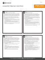
GUARANTEE TERMS AND CONDITIONS
W
A
R
R
A
N
T
Y
W
A
R
R
A
N
T
Y
1. SmartMetals Mounting Solutions guarantees that a product that SmartMetals
has determined to be defective as a result of decient manufacture or material
this will be repaired or – if necessary – replaced or you will be provided with a
replacing part (the previous always to be determined by SmartMetals), without
cost, on condition that a claim is made within the period of warranty, which is 5
years.
2. In the event of a claim being made under the terms of the warranty, the
product needs to be returned to SmartMetals accompanied by a RMA form,
which we will send on request. The freightcosts back and forth will always be
borne by the owner.
3. The guarantee provided by SmartMetals shall lapse:
• if a defect arises as the result of incorrect or inexpert assembly or installation.
• in case of improper use or any use not in accordance with the instructions.
• in case of normal wear and tear.
• if, without obtaining the written consent of SmartMetals, customer or a third
party have introduced changes to the product or have attempted to do so,
if other items have been attached to the product that should not be
attached, if products were processed or revised in some way other than was
instructed.
• if customer or a third party engaged by customer performed repairs without
the written consent of SmartMetals beforehand.
GB
Guarantee terms and conditions
1. SmartMetals Mounting Solutions garantiert, dass ein Produkt, bei dem
SmartMetals Defekte infolge von Fabrikations- oder Materialfehlern feststellt,
kostenlos repariert oder, falls notwendig, ersetzt wird, oder Ersatzteile werden
Ihnen zur Verfügung gestellt (das Vorstehende immer von SmartMetals zu
bestimmen) sofern die Reklamation innerhalb der gültigen Garantiezeit von 5
Jahren eingereicht wurde.
2. Im Falle dass Anspruch unter den Bedingungen der Garantie gemacht wird,
muss das Produkt SmartMetals durch eine RMA-Formular, die wir auf Anfrage
gerne zusenden, begleitet zurückgegeben werden. Die Frachtgebühren hin und
her werden immer vom Besitzer getragen.
3. Die Garantie von Smartmetals wird hinfällig:
• wenn ein Defekt auftritt aufgrund falscher oder unsachgemäßer Montage
oder Installation.
• im Falle einer missbräuchlichen Verwendung oder eine Verwendung nicht
den Anweisungen entsprechend.
• bei normalem Abnutzung.
• wenn, ohne die schriftliche Zustimmung von Smartmetals, Kunde oder ein
Dritter Änderungen am Produkt eingeführt haben oder versucht haben
dies zu tun, wenn andere Gegenstände am Produkt befestigt wurden, die
nicht befestigt sein sollten, wenn Produkte verarbeitet wurden oder in einigen
überarbeitet auf andere Weise als angewiesen wurde.
• wenn der Kunde oder ein Dritter von ihm beschäftigt Reparaturen ausgeführt
hat ohne die schriftliche Zustimmung von Smartmetals vorab.
DE
Garantiebedingungen
1. SmartMetals Mounting Solutions garantit que tout produit jugé défectueux
par SmartMetals du fait d’un vice de fabrication ou de matériaux, sera réparé
ou, si nécessaire, remplacé ou vous sera fourni avec une partie remplaçant (la
précédente toujours à déterminer par SmartMetals) sans coût supplémentaire,
à condition que la réclamation soit faite avant l’expiration de la période de
garantie qui est de 5 ans.
2. Dans le cas d’une réclamation faite en vertu des termes de la garantie, le
produit doit être retourné à SmartMetals accompagnée d’une forme de retour,
que nous vous enverrons sur demande. Les frais de transport aller-retour seront
toujours à la charge du propriétaire.
3. La présente garantie ne s’applique pas lorsque:
• si un défaut survient à la suite de l’assemblage ou l’installation incorrecte ou
inexpérimentée.
• en cas de mauvaise utilisation ou d’une utilisation non conforme aux
instructions.
• en cas d’usure normale.
• si, sans avoir obtenu le consentement écrit de SmartMetals, client ou un
tiers ont introduit des modications au produit ou ont tenté de le faire, si
d’autres éléments ont été apposées sur le produit qui ne devrait pas être
xé, si les produits ont été traités ou révisés d’une autre façon que ce qui
était demandé.
• si le client ou une tierce partie engagée par le client a eectué des
réparations sans le consentement écrit de SmartMetals au préalable.
FR
Conditions de garantie
1. SmartMetals Mounting Solutions garandeert dat in het geval een product
dat door SmartMetals ten gevolge van in gebreke gebleven vervaardiging
of gebrekkig materiaal als defect wordt beschouwd, deze kosteloos wordt
gerepareerd of indien noodzakelijk vervangen of u een vervangend onderdeel
toegestuurd krijgt (voorgaande te allen tijde te bepalen door SmartMetals),
onder voorwaarde dat de klacht binnen de geldende garantieperiode van 5
jaar wordt ingediend.
2. Indien er een beroep op de garantie wordt gedaan, dient het product
vergezeld van een RMA formulier, dat u op aanvraag door ons wordt
toegestuurd, aan SmartMetals te worden geretourneerd. Vrachtkosten heen en
terug komen te allen tijde ten laste van de eigenaar.
3. De garantie van SmartMetals komt te vervallen:
• indien een gebrek is ontstaan als gevolg van, of voortvloeit uit een onjuiste
c.q. onoordeelkundige montage of installatie.
• indien er sprake is van oneigenlijk gebruik of enig gebruik dat niet in
overeenstemming is met gebruiksaanwijzigingen.
• indien er sprake is van normale slijtage.
• indien er zonder schriftelijke toestemming van SmartMetals, opdrachtgever
of derden aan het product wijzigingen hebben aangebracht danwel
hebben getracht aan te brengen, daaraan andere zaken werden bevestigd
die daaraan niet bevestigd dienen te worden, indien deze werden ver- of
bewerkt op een andere dan de voorgeschreven wijze.
• indien opdrachtgever of een door hem ingeschakelde derde een reparatie
heeft verricht zonder voorafgaande schriftelijke toestemming van
SmartMetals.
NL
Garantievoorwaarden
W
A
R
R
A
N
T
Y
W
A
R
R
A
N
T
Y
W
A
R
R
A
N
T
Y
W
A
R
R
A
N
T
Y
W
A
R
R
A
N
T
Y
W
A
R
R
A
N
T
Y

Page 8
AG Neovo Technology B.V. • Molenbaan 9 • 2908 LL CAPELLE A/D IJSSEL • The Netherlands
FWL-01B
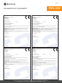
DECLARATION OF CONFORMITY
GB Declaration of conformity
Manufacturer:
SmartMetals Mounting Solutions BV
Vlietskade 8016
4241 WS ARKEL
THE NETHERLANDS
hereby declares that:
Floor supported wall lift FWL-01B
are compliant to the following directives:
Machinery Directive 2006/42/EG
EMC Directive 2014/30/EU
References to the relevant harmonised standards used, or references to the specications in relation
to which conformity is declared:
EN IEC 60204-1: 2016: Safety of machines - Electrical equipment of machines - Part 1: General
Requirements.
EN ISO14120: 2015: Safety of machines - Guards - General requirements for the design and
construction of xed and movable guards.
EN IEC 60335-1: 2012: Household and similar electrical appliances - Safety - Part 1: General
requirements
EN 614-1: 2006 + A1: 2009: Machine safety - Ergonomic design principles - Part 1: Terminology and
general principles
Arkel, 27 July 2020
Martijn Kleijweg
Quality & Product manager
DE Konformitätserklärung
Hersteller:
SmartMetals Mounting Solutions BV
Vlietskade 8016
4241 WS ARKEL
DIE NIEDERLANDE
erklärt hiermit daß:
Boden abgestützte Wandlift FWL-01B
sind konform mit den folgenden Richtlinien:
Maschinenrichtlinie 2006/42/EG
EMV-Richtlinie 2014/30/EU
Bezugnahme auf die verwendeten einschlägigen harmonisierten Normen oder Bezugnahme auf
Spezikationen, für die die Konformität erklärt wird:
EN IEC 60204-1: 2016: Sicherheit von Maschinen - Elektrische Ausrüstung von Maschinen - Teil 1:
Allgemeine Anforderungen.
EN ISO14120: 2015: Sicherheit von Maschinen - Schutzeinrichtungen - Allgemeine Anforderungen an
Gestaltung und Bau von festen und beweglichen trennenden Schutzeinrichtungen.
EN IEC 60335-1: 2012: Sicherheit elektrischer Geräte für den Hausgebrauch und ähnliche Zwecke -
Teil 1: Allgemeine Anforderungen
EN 614-1: 2006 + A1: 2009: Sicherheit von Machinen - Ergonomische Gestaltungsgrundsätze - Teil 1:
Begrie und allgemeine Leitsätze
Arkel, 27. Juli 2020
Martijn Kleijweg
Quality & Product manager
FR Déclaration of conformité
Fabricant:
SmartMetals Mounting Solutions BV
Vlietskade 8016
4241 WS ARKEL
LES PAYS-BAS
déclare que:
Lift mur supporté au sol FWL-01B
sont conformes aux directives suivantes:
Directive Machines 2006/42/EG
Directive CEM 2014/30/EU
Références aux normes harmonisées pertinentes utilisées ou références aux spécications par
rapport auxquelles la conformité est déclarée:
EN IEC 60204-1: 2016: Sécurité des machines - Équipement électrique des machines - Partie 1:
Exigences générales.
EN ISO14120: 2015: Sécurité des machines - Protecteurs - Prescriptions générales pour la
conception et la construction des protecteurs xes et mobiles.
EN IEC 60335-1: 2012: Appareils électrodomestiques et analogues - Sécurité - Partie 1: Prescriptions
générales
EN 614-1: 2006 + A1: 2009: Sécurité des machines - Principes ergonomique de conception - Partie
1: Terminologie et principes généraux
Arkel, 27 juillet 2020
Martijn Kleijweg
Quality & Product manager
NL Conformiteitsverklaring
Fabrikant:
SmartMetals Mounting Solutions BV
Vlietskade 8016
4241 WS ARKEL
NEDERLAND
verklaart hierbij dat:
Vloer afgesteunde wandlift FWL-01B
voldoen aan de volgende richtlijnen:
Machinerichtlijn 2006/42/EG
EMC-richtlijn 2014/30/EU
Verwijzingen naar de toegepaste relevante geharmoniseerde normen of van de specicaties waarop
de conformiteitsverklaring betrekking heeft:
EN IEC 60204-1: 2016: Veiligheid van machines - Elektrische uitrusting van machines - Deel 1:
Algemene Eisen.
EN ISO14120: 2015: Veiligheid van machines - Afschermingen - Algemene eisen voor het ontwerp en
de constructie van vaste en beweegbare afschermingen.
EN IEC 60335-1:2012: Huishoudelijke en soortgelijke elektrische toestellen - Veiligheid - Deel 1:
Algemene eisen
EN 614-1:2006+A1:2009: Veiligheid van machines - Ergonomische ontwerpprincipes - Deel 1:
Terminologie en algemene principes
Arkel, 27 juli 2020
Martijn Kleijweg
Quality & Product manager

Page 9
AG Neovo Technology B.V. • Molenbaan 9 • 2908 LL CAPELLE A/D IJSSEL • The Netherlands
FWL-01B
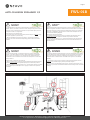
ANTI-COLLISION EXPLAINED 1/2
GB
Anti-collision
IMPORTANT
Aus Sicherheitsgründen wurde dieses Liftsystem mit einem integrierten Sensor alias
PIEZO™ ausgestattet. Der PIEZO™-Kollisionsschutz minimiert das Risiko von Schäden an
Hubsystem und Schirm, die durch Quetschen oder Blockieren aufgrund von Hindernissen
auf der Auf- und Abbewegung des Liftsystems verursacht werden. Beispiele sind in der
untenstehenden Abbildung dargestellt.
Bitte beachten Sie folgende Hinweise:
1. In gewissem Umfang erhöht die Funktion auch die persönliche Sicherheit, aber es
entspricht jedoch nicht den spezischen Gesetzen zur persönlichen Sicherheit.
2. Beachten Sie, daß PIEZO ™ für ca. 1 Sekunde nach Aktivierung der Liftsystems wird
ignoriert, was bedeutet was bedeutet daß der Lift schon eine Strecke überbrückt, ohne
Antikollisionsschutz.
DE
Antikollision
WICHTIG
Pour une sécurité optimisée, ce système lift est équipé d’un capteur intégré appelé
PIEZO™. L’anti-collision PIEZO™ minimise le risque d’endommager le système lift et
l’écran en raison d’un écrasement ou d’un blocage causé par des obstacles dans la
trajectoire de montée et de descente de l’ascenseur. Des exemples sont montrés dans
l’image ci-dessous.
Veuillez prendre en compte les notes suivantes:
1. Dans une certaine mesure, la fonction augmente également la sécurité des personnes,
mais elle n’est pas conforme à la législation spécique sur la sécurité des personnes.
2. Sachez que PIEZO ™ sera ignoré pendant env. 1 seconde après l’activation du système
lift, ce qui signie que le lift est déjà en train de voyager une distance sans protection
anticollision.
FR
Anti-collision
IMPORTANT
Voor optimale veiligheid is dit liftsysteem uitgerust met een geïntegreerde sensor, PIEZO™
genoemd. PIEZO™ anti-collision minimaliseert het risico op schade aan het liftsysteem en
scherm veroorzaakt door verdrukking of blokkering door obstakels die zich in de op- en
neerwaartse baan van de lift bevinden. Voorbeelden worden getoond in onderstaande
afbeelding.
1. Tot op zekere hoogte verhoogt het systeem ook de persoonlijke veiligheid, maar het
voldoet niet aan specieke wetgeving omtrent persoonlijke veiligheid.
2. Houd er rekening mee dat PIEZO™ gedurende ca. 1 seconde na het activeren van het
liftsysteem nog niet actief is wat betekent dat de lift al afstand overbrugt zonder anti-collision
beveiliging.
NL
Anti-collision
BELANGRIJK
For optimised safety this lift system has been tted with an integrated sensor, called
PIEZO™. PIEZO™ anti-collision minimises the risk for damages to lift system and screen
caused by crushing or blocking due to obstacles in the up and down trajectory of the lift.
Examples are shown in the image below.
Please take into account following notes:
1. To a certain extent, the function also increases personal safety, but it does not comply
with specic legislation on personal safety.
2. Be aware that PIEZO™ will be ignored for approx. 1 second after activating the
lift system, which means that the lift is already bridging distance without anti-collision
protection.
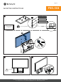
Although this graphic shows lifting columns applied in a desk furniture instead of a monitor lift system, it’s the red circled squeezing examples that are of importance.

Page 10
AG Neovo Technology B.V. • Molenbaan 9 • 2908 LL CAPELLE A/D IJSSEL • The Netherlands
FWL-01B
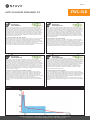
ANTI-COLLISION EXPLAINED 2/2
GB
Anti-collision
FUNCTIONALITY
PIEZO ™ ist ein in die Liftsäule integrierter elektronischer Sensor, der auf Lastwechsel
reagiert. Fährt das Liftsystem gegen ein Hindernis, ändert sich die Last. Dieser Lastwechsel
wird von PIEZO ™ erfasst und das Signal wird an die Steuerbox gesendet. Die Steuerbox
stoppt das System sofort und veranlasst es, in die entgegengesetzte Richtung zu fahren,
um die Kollision zu vermeiden / zu minimieren. Diese Bewegung hält nur 4 Sekunden und
nicht länger als die vorherige Bewegung. Bei der Kollision tritt eine bestimmte Kraft (N)
auf, bevor das System anhält und in die entgegengesetzte Richtung fährt. Die typische
Kraft (N) ist in der folgenden Grak 1 dargestellt. Das PIEZO ™ -Systems basiert aud den
Maschinenrichtlinien EN12453 + EN12445 für Geräte, bei denen Hindernisse / Personen
gequetscht werden können.
„Die Bustürrichtlinie“: EN 12453 + EN12445
Die folgende Grak 1 entspricht der max. Kräfte in den Bereichen „Industrie-, Geschäfts-
und Garagentore. Sicherheit bei der Verwendung von kraftbetätigten Türen. Anforderungen
„Norm und Prüfverfahren“: EN12453 + EN12445. Diese Richtlinie beschreibt, wie die
„Quetsch“ Funktion und die max. Kraft, mit der das System im Laufe der Zeit quetschen darf.
Der blaue Bereich zeigt die max. Kraft und Zeitraum, in dem die Kraft anwesend sein kann.
In den meisten Fällen entspricht das PIEZO ™ -System der Norm, in einigen Fällen kann es
JEDOCH zu Ausnahmen kommen, wie die rote Kurve in der folgenden Abbildung zeigt.
DE
Antikollision
FUNKTIONALITÄT
PIEZO ™ est un capteur électronique intégré dans la colonne du lift, qui réagit aux
changements de charge. Si le lift entre en collision avec un obstacle, la charge changera.
Ce changement de charge est capté par PIEZO ™ et le signal est envoyé au boîtier de
commande. Le boîtier de commande arrête immédiatement le système et le fait rouler dans
le sens opposé pour éviter / minimiser la collision. Ce mouvement ne durera que 4 secondes
et jamais plus longtemps que le mouvement précédent. Lors de la collision, il y aura une
certaine force (N) avant que le système s’arrête et roule dans la direction opposée. La force
typique (N) est illustrée dans le graphique 1 ci-dessous. Le système PIEZO ™ est basé sur
les directives de la machine EN12453 + EN12445 pour les équipements où des obstacles /
personnes peuvent être piégés.
“La directives sur les portes de bus”: EN 12453 + EN12445
Le graphique 1 ci-dessous est similaire aux forces maximales des «Portes et portails
industriels, de l’entreprise et de garage. Sécurité lors de l’utilisation de portes électriques.
Exigences techniques de sécurité et procédures d’essai ”: EN12453 + EN12445. Cette
directive décrit comment tester la fonction “pincement” et la puissance maximale avec
laquelle le système peut pincer au l de temps. La zone bleue indique la puissance maximale
et la période de temps pendant laquelle la puissance peut être présente.
Dans la plupart des cas, le système PIEZO ™ sera conforme à la directive, MAIS dans
certains cas, il peut y avoir des exceptions, illustrées par la courbe rouge dans l’illustration
ci-dessous.
FR
Anti-collision
FONCTIONNALITÉ
PIEZO™ is een ingebouwde elektronische sensor in de liftkolom, die reageert op
veranderingen in de belasting. Als het liftsysteem tegen een obstakel aanloopt, verandert de
belasting, wat wordt opgemerkt door PIEZO™ die vervolgens een signaal naar de control
box stuurt. De control box stopt het systeem onmiddelijk en laat het in de tegenovergestelde
richting bewegen om botsing te voorkomen/minimaliseren. Deze beweging duurt maar 4
seconden en nooit langer dan de voorgaande beweging. Bij de botsing komt een bepaalde
kracht (N) vrij voordat het systeem stopt en in tegenovergestelde richting beweegt.
Deze kracht (N) wordt weergegeven in de afbeelding hieronder. Het PIEZO™ systeem
is gebaseerd op de machinerichtlijnen EN12453 + EN12445 voor apparatuur waarbij
obstakels/personen bekneld kunnen raken.
“De busdeur richtlijn”: EN 12453 + EN12445
De onderstaande afbeelding 1 is vergelijkbaar met de max. krachten in de “Industriële,
bedrijfs- en garagedeuren en hekken. Veiligheid bij het gebruik van elektrisch aangedreven
deuren. Technische veiligheidseisen en testprocedures”: EN12453 + EN12445. Deze richtlijn
schrijft voor hoe de “knel” functie getest dient te worden en de max. kracht waarmee het
systeem na verloop van tijd kan knellen. Het blauwe gebied geeft de maximale kracht en
tijdsperiode aan waarin de kracht aanwezig kan zijn.
In de meeste gevallen voldoet het PIEZO™ -systeem aan de richtlijn, MAAR in sommige
gevallen kunnen er uitzonderingen zijn, weergegeven met de rode curve in de onderstaande
afbeelding.
NL
Anti-collision
FUNCTIONALITEIT
PIEZO™ is a built-in electronic sensor in the lift column, which reacts on load changes. If
the lift system drives into an obstacle the load will change. This load change is picked up
by PIEZO™ and the signal is sent to the control box. The control box immediately stops the
system and makes it drive in the opposite direction avoiding/minimising the collision. This
drive will only last for 4 seconds and never longer than the previous drive. At the collision,
there will be a certain force (N) before the system stops and drives in the opposite direction.
The typical force (N) is shown in graphic 1 below. The objective of the PIEZO™ system is
that it should follow the ocial test standards EN12453 + EN12445 for equipment where
obstacles/persons can be squeezed.
“The bus door standard”: EN 12453 + EN12445
The below graphics 1 is similar to the max. forces in the “Industrial, commercial and garage
doors and gates. Safety in use of power operated doors. Requirements “standard and
test methods”: EN12453 + EN12445. This standard describes how to test the “Squeezing”
function and the max. force with which the system is allowed to squeeze over time. The blue
area illustrates the max. force and time period in which the force may be present.
In most cases, the PIEZO™ system will comply with the standard, BUT in some cases there
may be exceptions, illustrated by the red curve in the below illustration.
Graphics 1:
La page est en cours de chargement...
La page est en cours de chargement...
La page est en cours de chargement...
La page est en cours de chargement...
La page est en cours de chargement...
La page est en cours de chargement...
La page est en cours de chargement...

Page 18
AG Neovo Technology B.V. • Molenbaan 9 • 2908 LL CAPELLE A/D IJSSEL • The Netherlands
FWL-01B
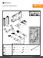
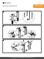
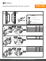
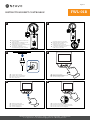
INSTRUCTIONS RESET CONTROLBOX
GB
DE
FR
NL
- Check the connection from the remote
to the controlbox
- Überprüfen Sie die Verbindung von der
Fernbedienung zur Controlbox
- Vérifiez la connexion de la télécommande
au boîtier de commande
- Controleer de verbinding van de
afstandsbediening naar de controlbox
GB
DE
FR
NL
- Check the connection from
the power plug to the controlbox
- Überprüfen Sie die Verbindung vom
Netzstecker zur Controlbox
- Vérifiez la connexion de la prise
d’alimentationau boîtier de commande
- Controleer de verbinding van de
stekker naar de controlbox
GB
DE
FR
NL
- Connect the power plug
- Schließen Sie den Netzstecker an
- Brancher la fiche d'alimentation
- Sluit de stekker aan
GB
DE
FR
NL
- Move to lowest position
- Beweg zur untersten Position
- Déplacer vers la position la plus basse
- Ga naar de laagste positie
GB
DE
FR
NL
- Release the down button
- Lassen Sie die Abwärtstaste los
- Relâchez le bouton bas
- Laat de omlaagknop los
30s
GB
DE
FR
NL
- Push the down button for 30 sec
- Drücken Sie die Abwärtstaste 30 Sekunden lang
- Appuyez sur le bouton bas pendant 30 secondes
- Druk 30 seconden op de omlaagknop
1 2
3 4
5 6
La page est en cours de chargement...
La page est en cours de chargement...
La page est en cours de chargement...
La page est en cours de chargement...
-
 1
1
-
 2
2
-
 3
3
-
 4
4
-
 5
5
-
 6
6
-
 7
7
-
 8
8
-
 9
9
-
 10
10
-
 11
11
-
 12
12
-
 13
13
-
 14
14
-
 15
15
-
 16
16
-
 17
17
-
 18
18
-
 19
19
-
 20
20
-
 21
21
-
 22
22


dans d''autres langues
- English: AG Neovo FWL-01B User manual
- Deutsch: AG Neovo FWL-01B Benutzerhandbuch
- Nederlands: AG Neovo FWL-01B Handleiding
Documents connexes
Autres documents
-
iiyama MD 052W7150K Manuel utilisateur
-
-
ATC RFA30/15-TE2 Assembly Instruction Manual
-
Ricatech RR300 Manuel utilisateur
-
Ricatech RTT77 Manuel utilisateur
-
Ricatech RTT88 Manuel utilisateur
-
Ricatech RMC200 Manuel utilisateur
-
Ricatech PR220 Manuel utilisateur
-
-
Ricatech RMC100 - 5 in 1 MUSIC CENTER Manuel utilisateur