
T9 SMART THERMOSTAT
RCHT9510WFW2019
Installation Guide
Online Guides
Resideo.com

2
M38354
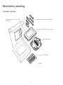
Read before installing.
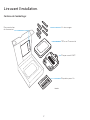
Included in your box:
Thermostat
Literature
Screws and anchors
T9 Smart Thermostat
UWP Wallplate
Wire labels

3
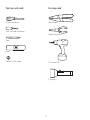
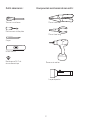
Tools you will need: You may need:
Phillips screwdriver Wire Stripper
Home WiFi Password
Small flat head screwdriver
Needle-nose pliers
Pencil
Drill and drill bit
Level
Flashlight

4
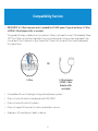
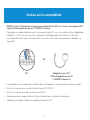
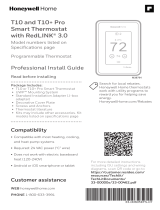
Compatibility Section
• REQUIRED: A CWire (common wire) is needed for 24 VAC power. If you do not have a CWire,
a FREE CWire Adapter offer is included.
This guide will help you determine if you have a CWire or will need to use a CWire Adapter (Step
10). The CWire is a wire that originates from your heating and cooling system and needs to be
connected to the C terminal on your thermostat. There is no universal color used to designate
this type of wire.
• Compatible with most heating/cooling, and heat pump systems
• Does not work with electric baseboard heat (120240V)
• Does not work with millivolt systems
• Does not support S terminals for indoor and outdoor sensors
• Android or iOS smartphone, tablet, or device
C
CU
GY
GY
A
OR
CWire CWire Adapter
(FREE CWire
Adapter offer
included)

5
For help, see:
ONLINE GUIDES AND SUPPORT VIDEOS AT: Resideo.com
SOCIAL Twitter: @Honeywell_Home, Facebook: Honeywell Home
Or contact:
PHONE 18006333991
CAUTION: ELECTRICAL HAZARD
Can cause electrical shock or equipment damage. Disconnect power before beginning installation.
CAUTION: EQUIPMENT DAMAGE HAZARD
Compressor protection is bypassed during testing. To prevent equipment damage, avoid cycling the compressor quickly.
CAUTION: MERCURY NOTICE
If this product is replacing a control that contains mercury in a sealed tube, do not place the old control in the trash. Contact
your local waste management authority for instructions regarding recycling and proper disposal.

6
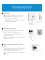
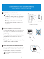
Removing your old thermostat
You will need: Screwdriver, needle-nose pliers
OFF
ON
75
1
2
3
Turn off power
To protect your equipment, turn off the power
at the breaker box or switch that controls you
heating and cooling equipment.
Note: The thermostat off switch will not turn off
the power to the equipment.
Check that your system is off
Change the temperature on your old thermostat so
that your system starts heating or cooling.
If you don’t hear or feel the system turn on within 5
minutes, the power is off.
Note: If you have a digital thermostat that has a blank
display, skip this step.
Remove your existing thermostat from the wall
plate
On most thermostats, you can take off the thermostat
by grasping and gently pulling. Some thermostats
may have screws, buttons, or clasps.
Do not remove any wires from your thermostat at
this time!
OR
OFF
Breaker box
Switch

7
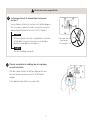
5
4
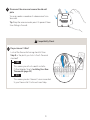
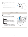
Take a picture of your existing wall plate’s wiring
In order to capture all of the letters next to the
terminals, be sure to take multiple pictures from
different angles.
You may need to reference this image later.
Do you have a line voltage system?
Line voltage systems have thick black wires with
wire nuts or are labeled high voltage (120V or
higher).
Your system is not compatible. Go to
Resideo.com to find a pro installer in your
area.
Continue to the next step.
Wire nut
Thick black wire
Compatibility Check
YES
NO

8
6
7
Remove any jumpers
A jumper is used to connect two terminals. It may look
like a small staple or a colored wire.
Do not discard.
Keep jumpers with your old wallplate.
Label the wires
Use the stickers provided with your new thermostat to
label each wire on your existing wall plate.
Do not label jumpers. Your new thermostat does not
need jumpers.
Example
of a jumper
Terminals
YRRC
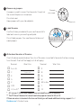
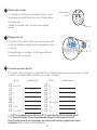
8Write down the colors of the wires
Check the boxes and write down the color of the wires connected to terminals that are coming
from the wall. Check all that apply (not all will apply).
Terminal Wire Color Terminal Wire Color
¨A or L/A ¨R
¨CRequired* ¨Rc
¨E¨Rh
¨G¨W
¨K¨W2 or Aux
¨O/B ¨Y
¨U (1 or 2)** ¨Y2
* A C-wire or CWire Power Adapter (see included free offer) is required.
** The T9 Smart thermostat cannot control equipment wired to U1 or U2.
If there are wires in terminals that are not listed, you will need additional wiring support. Visit
Resideo.com to find out more.

9
10 Do you have a CWire?
Look at the thermostat wiring checklist from
Step 8, or the photo you took. Is the CTerminal
checked?
This means you will not need to install a
CWire Adapter. Skip to Installing Your New
Thermostat (page 13).
This means you don’t have a C-wire connected
to your thermostat. Continue to next step.
Compatibility Check
YES
NO
9Disconnect the wires and remove the old wall
plate
You may need a screwdriver to release wires from
terminals.
Tip: Wrap the wires around a pencil to prevent them
from falling in the wall.
C
CU
GY
GY
A

10
11
12
Do you have a zoning panel?
You have a zoning panel if you have multiple
thermostats and one furnace or heating system.
CWire Adapter installation is more complicated
on zoned systems. Go to Resideo.com to find a
pro installer in your area.
Proceed to the next step.
Do you have an unused wire?
Look at the bundle of wires coming from the wall.
Note: You may have to pull the bundle of wires out
from the wall to find the unused wire.
Continue to Step 13.
See the CWire Power Adapter FREE OFFER
included in the thermostat box. Follow the
instructions that come with the CWire Power
Adapter, and then return to page 13 of this
guide to complete the installation.
Compatibility Check
YES
YES
NO
NO
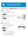
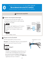
Only complete this section if you answered No to Step 10
Connecting Your Unused CWire
You will need: Screwdriver, flashlight, wire strippers
Thermostat
Furnace
Example of unused C-wire
Zoning
Panel

11
13 Label unused wire
Label your unused wire with the
provided “C” sticker label. You may need
to use a wire stripper to expose at least
1/4 inch of the wire.
Note: If you have multiple unused wires,
then label only one wire and make note
of the color here:
-
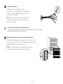
Go to your furnace or heating system
This system is often located in your basement, attic or garage.
Bring a flashlight and screwdriver.
14 Remove cover from furnace or heating system
Open the heating and cooling system’s cover to find
the control board. You should see the same terminal
labels that are on your thermostat.
Note: You may need to unscrew the cover. The
control board may be at the top or bottom.
G
C
R
W
Y

12
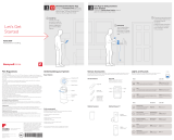
16
15
17
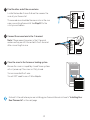
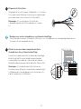
Connect the unused wire to the C-terminal
Note: If there are existing wires in the C-terminal,
make sure they are still connected to the C-terminal
after connecting this wire.
Find the other end of the unused wire
Locate the bundle of wires that are the same as the
ones at your thermostat.
The unused wire should be the same color as the one
near your existing thermostat. See Step 13 for the
color you wrote down.
Close the cover to the furnace or heating system
Be sure the cover is completely closed. Some systems
will not power up if the cover isn’t fully closed.
You’ve connected the C-wire.
You will NOT need to use a CWire Adapter.
G
C
R
W
Y
G
C
R
W
Y
-
Go back to the wall where you are installing your thermostat and continue to “Installing Your
New Thermostat” on the next page.

13
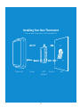
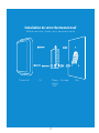
Installing Your New Thermostat
You will need: Level, pencil, drill and a drill bit
Thermostat Screws UWP
wallplate
WallAnchors

14
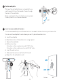
18
19
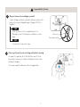
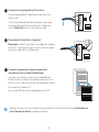
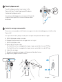
Position wall plate
Pull open the wall plate that was included with your
new thermostat. Insert the bundle of wires through
the back of the wall plate.
Make sure at least 1/4-inch of each wire is exposed
for easy insertion into the wire terminals.
Insert recommended wall anchors
It is recommended that you use the wall anchors included in the box to mount your thermostat.
You can use the wall plate to mark where you want to place the wall anchors.
a) Level the wall plate
b) Mark the location of the wall anchors using a pencil
c) Remove the wall plate
d) Drill anchor holes.
If your box contains red anchors, drill 7/32” holes.
If your box contains yellow anchors, drill 3/16” holes.
e) Insert the wall anchors
f) Make sure the anchors are flush with the wall
g) Reposition the wall plate on wall
-
UWP
Anchors Wall

15
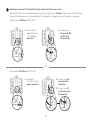
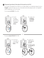
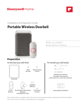
1. Ensure the
right R-switch
is in the up
position.
1. Set right
R-switch to the
down position.
UWP
20 Determine Correct RSwitch Position and Insert R-wire or wires
Set the R-switch up or down based on your wiring notes in Step 8. Insert wires into the inner
holes of the terminals on the wall plate. The tabs will stay down once the wire is inserted.
If you have 1 RWire (R, RC, RH):
If you have 2 RWires (R, RC, RH):
2. Insert your
R-wire (R, Rh
or Rc) into
R-terminal.
2. Insert your Rc
wire into Rc-
terminal.
3. Insert your R
or Rh wire into
R-terminal.
OR

16
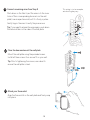
22
23
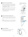
Close the door and mount the wall plate
Mount the wall plate using the provided screws.
Install all three screws for a secure fit on your wall.
Tip: Prior to tightening the screws, use a level to
ensure the wall plate is level.
Attach your thermostat
Align the thermostat on the wall plate and firmly snap
into place.
21 Connect remaining wires from Step 8
Push down on the tabs to put the wires into the inner
holes of their corresponding terminals on the wall
plate (one wire per terminal) until it is firmly in place.
Gently tug on the wires to verify they are secure.
Tip: If you need to release the wires again, push down
the terminal tabs on the sides of the wall plate.
This wiring is just an example,
actual wiring may vary.

17
24
25
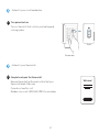
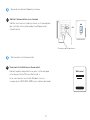
Turn power back on
Turn on the switch that controls your heating and
cooling system.
Complete setup on the thermostat
Remove the protective film and confirm that your
thermostat reads “Welcome.”
If you do not see this, visit
Resideo.com or call 18006333991 for more help.
Go back to your circuit breaker box.
Go back to your thermostat.
OFF
ON
ON
Breaker box
Switch
Welcome!

18
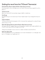
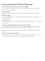
Getting the most from the T9 Smart Thermostat
Prioritize Rooms (Requires optional Wireless Room Sensor accessory)
Prioritize a specific room or multiple rooms, or let comfort follow your move using built-in motion
detection.
Control on the Go
Adjust your thermostat from anywhere using your tablet or smartphone.
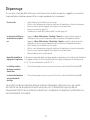
Save Energy
With geofencing, you can save money on the most expensive part of your energy bill while you’re
away.
Simple Installation
The thermostat automatically programs itself. Just answer a few simple questions and you’ll be up
and running in no time.
WholeHome Range (Requires optional Wireless Room Sensor accessory)
With up to a 200-foot* range, 20 sensors with temperature, humidity, and occupancy detection can
connect to your thermostat from throughout your home.
*Range can vary based on home construction, wireless interference, and other factors.
Know Your Home Is Safe
Get customizable alerts on your mobile device such as when the basement is so cold a pipe could
burst, or if the baby’s room is getting too hot.

19
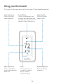
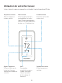
Using your thermostat
The screen will wake up by pressing the center area of the displayed temperature.
74
2
18%
Indoor Temperature
Displays the current
indoor temperature.
Adjust Temperature
Touch the up and down
arrows to set your desired
temperature.
Current Priority
Displays the type of priority and
number of rooms being prioritized.
Extend your thermostat’s reach with
additional Wireless Room Sensors.
Menu
Contains features such
as mode, fan, schedule,
priority, and other
thermostat settings.
Indoor Humidity
Displays the current
indoor humidity.
Desired Temperature
Displays the desired
temperature.

20
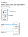
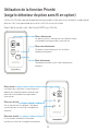
Using Priority
(Requires optional Wireless Room Sensor accessory)
Priority creates an average temperature in your home based on specific rooms. This allows you to
prioritize comfort where you want it.
From the Home screen, select MENU, then Priority.
Selected Rooms
Rooms you manually select create an average
temperature in your home.
Unselected Room
Will not contribute to the average temperature.
Selected Room
Will contribute to the average temperature.
72 72
72 72
72 72
72 72
Active Rooms
Rooms with detected motion are automatically
selected to create an average temperature in
your home.
Room without Activity
No motion is detected. Will not contribute to
the average temperature.
Room with Activity
Motion is detected. Will contribute to the
average temperature.
La page est en cours de chargement...
La page est en cours de chargement...
La page est en cours de chargement...
La page est en cours de chargement...
La page est en cours de chargement...
La page est en cours de chargement...
La page est en cours de chargement...
La page est en cours de chargement...
La page est en cours de chargement...
La page est en cours de chargement...
La page est en cours de chargement...
La page est en cours de chargement...
La page est en cours de chargement...
La page est en cours de chargement...
La page est en cours de chargement...
La page est en cours de chargement...
La page est en cours de chargement...
La page est en cours de chargement...
La page est en cours de chargement...
La page est en cours de chargement...
La page est en cours de chargement...
La page est en cours de chargement...
La page est en cours de chargement...
La page est en cours de chargement...
La page est en cours de chargement...
La page est en cours de chargement...
La page est en cours de chargement...
La page est en cours de chargement...
-
 1
1
-
 2
2
-
 3
3
-
 4
4
-
 5
5
-
 6
6
-
 7
7
-
 8
8
-
 9
9
-
 10
10
-
 11
11
-
 12
12
-
 13
13
-
 14
14
-
 15
15
-
 16
16
-
 17
17
-
 18
18
-
 19
19
-
 20
20
-
 21
21
-
 22
22
-
 23
23
-
 24
24
-
 25
25
-
 26
26
-
 27
27
-
 28
28
-
 29
29
-
 30
30
-
 31
31
-
 32
32
-
 33
33
-
 34
34
-
 35
35
-
 36
36
-
 37
37
-
 38
38
-
 39
39
-
 40
40
-
 41
41
-
 42
42
-
 43
43
-
 44
44
-
 45
45
-
 46
46
-
 47
47
-
 48
48


Honeywell RCHT9610WFSW2003/U Guide d'installation
- Taper
- Guide d'installation
- Ce manuel convient également à
dans d''autres langues
Documents connexes
-
Honeywell RCHT8610WF Guide d'installation
-
-
Honeywell RCHT8612WF20052PK Manuel utilisateur
-
-
Honeywell T6 Pro Programmable Thermostat Le manuel du propriétaire
-
-
Honeywell THX321WFS2001W Mode d'emploi
-
-
-
Autres documents
-
 Honeywell Home RTH Series T5 Smart Thermostat Guide d'installation
-
resideo SMHOM9585WLD3KIT Manuel utilisateur
-
 Honeywell Home THX321WFS2001W Guide d'installation
-
Honeywell Home T6 Mode d'emploi
-
-
 Honeywell Home RCHS5200WF1004/U Guide de démarrage rapide
-
Honeywell Home T3 Pro Installation Instructions Manual
-
Honeywell Home THX321WFS2001W/U Mode d'emploi
-
 Honeywell Home RDWL311A2000/U Guide d'installation
-
 Honeywell Home TH6320WF2003/U Mode d'emploi


