Whirlpool ACMK 6110 / WH / 3 Mode d'emploi
- Catégorie
- Plaques de cuisson
- Taper
- Mode d'emploi
Ce manuel convient également à

ACMK 6110/WH/3
ACMK 6110/IX/2
ACMK 6110/IX/3

English
GB
Operating Instructions
COOKER AND OVEN
Contents
Operating Instructions,2
Description of the appliance-Overall view,5
Description of the appliance-Control Panel,6
Installation,7
Start-up and use,12
Care and maintenance,15
FR
Français
Mode d’emploi
CUISINIERE ET FOUR
Sommaire
Mode d’emploi,2
Description de l’appareil-Vue d’ensemble, 5
Description de l’appareil-Tableau de bord, 6
Installation,18
Mise en marche et utilisation,24
Nettoyage et entretien,27
AR
ﻞﻴﻐﺸﺘﻟا تﺎﻤﻴﻠﻌﺗ
خﺎّﺒﻃ
تﺎﻳﻮﺘﺤﻤﻟا
ﻞﻴﻐﺸﺘﻟا
تﺎﻤﻴﻠﻌﺗ
زﺎﻬﺠﻟا
ﻒﺻو
ﺔﻣﺎﻋ ةﺮﻈﻧ
ﻢﻜﺤﺘﻟا ﺔﺣﻮﻟ
ﺐﻴﻛﺮﺘﻟا
ماﺪﺨﺘﺳﻻاو ﻞﻴﻐﺸﺘﻟا
ﺢﺋﺎﺼﻧو رﺬﺣ ﻞﺋﺎﺳو
ﺔﻧﺎﻴﺼﻟاو
ﺔﻳﺎﻨﻌﻟا
EnglishEnglishEnglishEnglish
W ARNINGS,3
ATTENTION,4
WARRANTY
Duration & Coverage
,17
GARANTIE
Durée et couvertu
re
,29

3
.
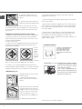
WARNING: The appliance and its
accessible parts become hot during
use.
Care should be taken to avoid
touching heating elements.
Children less than 8 years of
age shall be kept away unless
continuously supervised.
This appliance can be used by
children aged from 8 years and
above and persons with reduced
physical, sensory or mental
capabilities or lack of experience and
knowledge if they have been given
supervision or instruction concerning
use of the appliance in a safe
way and understand the hazards
involved. Children shall not play with
the appliance. Cleaning and user
maintenance shall not be made by
children without supervision.
WARNING: Unattended cooking on a
hob with fat or oil can be dangerous
and may result in fire.
NEVER try to extinguish a fire with
water, but switch off the appliance
and then cover flame e.g. with a lid
or a fire blanket.
Do not use harsh abrasive cleaners
or sharp metal scrapers to clean
the oven door glass since they can
scratch the surface, which may result
in shattering of the glass.
The internal surfaces of the
compartment (where present) may
become hot.
Never use steam cleaners or
pressure cleaners on the appliance.
Remove any liquid from
the lid before opening it.
Do not close the glass cover (if
present) when the gas burners or
electric hotplates are still hot.
WARNING: Ensure that the appliance
is switched off before replacing
the lamp to avoid the possibility of
electric shock.
CAUTION: the use of inappropriate
hob guards can cause accidents.
GB
WARNING
When you place the rack inside,
make sure that the stop is directed
upwards and in the back of the cavity.

FR
ATTENTION: cet appareil ainsi que
ses parties accessibles deviennent
très chauds pendant leur fonctionne-
ment.
Il faut faire attention de ne pas tou-
cher les éléments chauffants.
Ne laisser s’approcher les enfants
de moins de 8 ans à moins qu’ils ne
soient sous surveillance constante.
Le présent appareil peut être utilisé
par des enfants de plus de 8 ans et
par des personnes présentant des
capacités physiques, sensorielles
ou mentales réduites ou n’ayant pas
l’expérience ou les connaissances
nécessaires, à condition qu’ils soient
sous bonne surveillance ou qu’ils
aient reçu les instructions nécessai-
res pour une utilisation de l’appareil
en toute sécurité et à condition qu’ils
se rendent compte des dangers
encourus. Les enfants ne doivent
pas jouer avec l’appareil. Les opéra-
tions de nettoyage et d’entretien ne
doivent pas être effectuées par des
enfants non surveillés.
ATTENTION: laisser un récipient de
cuisson contenant de l’huile ou de la
graisse sur le foyer est dangereux et
risque d’entraîner un incendie.
Il ne faut JAMAIS essayer d’éteindre
une flamme ou un incendie avec de
l’eau! Il faut éteindre l’appareil et
couvrir la flamme avec un couvercle,
par exemple, ou avec une couverture
anti-feu.
Ne pas utiliser de produits abrasifs
ni de spatules métalliques coupan-
tes pour nettoyer la porte du four en
verre, sous peine d’érafler la surface
et de briser le verre.
Les surfaces intérieures du tiroir (s’il
y en a un) peuvent devenir chaudes.
Ne jamais nettoyer l’appareil avec
des nettoyeurs vapeur ou haute pres-
sion.
Essuyer tout liquide pouvant se
trouver sur le couvercle avant de
l’ouvrir. Ne pas abaisser le couvercle
en verre (s’il y en a un) tant que les
brûleurs gaz ou la plaque électrique
sont chauds.
ATTENTION: s’assurer que l’appareil
est éteint avant de procéder au rem-
placement de l’ampoule, afin d’éviter
tout risque d’électrocution.
ATTENTION: l’utilisation de protec-
tions de table inappropriées peut
causer des incendies.
ATTENTION
Lors de l’introduction de la grille,
s’assurer que l’arrêt est bien tourné
vers le haut et se trouve dans la par-
tie arrière de l’enceinte.
Lors de l’introduction de la grille,
s’assurer que l’arrêt est bien tourné
vers le haut et se trouve dans la par-
tie arrière de l’enceinte.
.
4

5
2
3
4
5
8
12
13
14
1
7
6
10
11
6
9
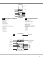
1.Hob burner
2.Hob Grid
3.Control panel
4.Sliding grill rack
5.DRIPPING pan
6.Adjustable foot
7.Containment surface for spills
8.GUIDE RAILS for the sliding racks
9.position 5
10.position 4
11.position 3
12.position 2
13.position 1
14.Glass Cover
Description of the appliance
Overall view
GB
1.Brûleur à gaz
2.Grille du plan de cuisson
3.Tableau de bord
4. Support GRILLE
5. Support LECHEFRITE
6.Pied de réglage
7.Plateau du plan de cuisson
8. GLISSIERES de coulissement
9. niveau 5
10.niveau 4
11.niveau 3
12.niveau 2
13.niveau 1
Description de l’appareil
Vue d’ensemble
FR
زﺎﻐﻟا قﺮﺤﻣ
فﺮﻟا ﺔﻜﺒﺷ
ﻢﻜﺤﺘﻟا ﺔﺣﻮﻟ
ةاﻮﺸﻤﻟا ﻞﻣﺎﺣ
ﻂﻴﻘﻨﺘﻟا ﺔﻴﻨﻴﺻ
ةﺮﻳﺎﻌﻤﻠﻟ ﺔﻠﺑﺎﻗ ﻞﺟر
*ﻲﺟﺎﺟز ءﺎﻄﻏ
5 ﻊﺿﻮﻟا
4 ﻊﺿﻮﻟا
3 ﻊﺿﻮﻟا
2 ﻊﺿﻮﻟا
ةﺮﻳﺎﻌﻤﻠﻟ ﺔﻠﺑﺎﻗ ﻞﺟر
ﺮﺛﺎﻨﺘﻠﻟ ﻖﻳﻮﻄﺘﻟا ﺢﻄﺴﻣ
ﻪﻴﺟﻮﺘﻟا تارﺎﺴﻣ
فﻮﻓﺮﻟا قﻻﺰﻧﻻ
1 ﻊﺿﻮﻟا
AR

GB
6
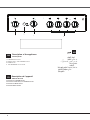
Description of the appliance
Control panel
GB
1.THERMOSTAT knob
2.OVEN LIGHT / ROTISSERIE button
3.TIMER knob
4. Hob BURNER control knob
Description de l’appareil
Tableau de bord
FR
1.Manette du THERMOSTAT
2.Bouton ECLAIRAGE/ TOURNEBROCHE
3.Manette du MINUTEUR
4.Manette BRULEURS
1
2
3
4
AR
ﻢﻜﺤﺘﻟا ﺔﺣﻮﻟ
ﺔﻴﺋﺎﺑﺮﻬﻛ ﻦﻴﺨﺴﺗ ﺔﺤﻴﻔﺼﺑ ﻢﻜﺤﺗ
ﻦﻴﺨﺴﺘﻟﺍ ﺔﺤﻴﻔﺻ ﺡﺎﺘﻔﻣ
ﺔﻴﺋﺎﺑﺮﻬﻜﻟﺍ
ﺭﺎﻴﺘﺧﻻﺍ ﺡﺎﺘﻔﻣ
ﺔﻋﺎﺳ حﺎﺘﻔﻣ
ﺖﻴﻗﻮﺘﻟا
*
*
رز
نﺮﻔﻟا ةءﺎﺿا و يﻮﺸﻟا روﺪﻣ
*
1.
2.
3.
4.

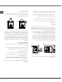
7
GB
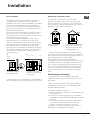
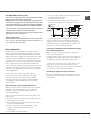
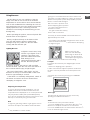
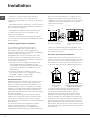
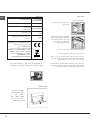
Room ventilation
The appliance may only be installed in permanently-
ventilated rooms, according to current national
legislation. The room in which the appliance is installed
must be ventilated adequately so as to provide as
much air as is needed by the normal gas combustion
process (the flow of air must not be lower than 2 m
3
/h
per kW of installed power).
The air inlets, protected by grilles, should have a duct
with an inner cross section of at least 100 cm
2
and
should be positioned so that they are not liable to even
partial obstruction (see figure A).
These inlets should be enlarged by 100% - with a
minimum of 200 cm
2
- whenever the surface of the
hob is not equipped with a flame failure safety device.
When the flow of air is provided in an indirect manner
from adjacent rooms (see figure B), provided that
these are not communal parts of a building, areas with
increased fire hazards or bedrooms, the inlets should
be fitted with a ventilation duct leading outside as
described above.
Adjacent room Room
requiring
ventilation
Disposing of combustion fumes
The disposal of combustion fumes should be
guaranteed using a hood connected to a safe and
efficient natural suction chimney, or using an electric
fan that begins to operate automatically every time the
appliance is switched on (see figure).
Installation
A
A B
After prolonged use of the appliance, it is advisable to
open a window or increase the speed of any fans used.
The liquefied petroleum gases are heavier than air
and collect by the floor, therefore all rooms containing
LPG cylinders must have openings leading outside so
that any leaked gas can escape easily.
LPG cylinders, therefore, whether partially or
completely full, must not be installed or stored in rooms
or storage areas that are below ground level (cellars,
etc.). Only the cylinder being used should be stored
in the room; this should also be kept well away from
sources of heat (ovens, chimneys, stoves) that may
cause the temperature of the cylinder to rise above
50°C.
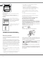
Positioning and levelling
It is possible to install the appliance alongside
cupboards whose height does not exceed that of the
hob surface.
Make sure that the wall in contact with the back of
the appliance is made from a non-flammable, heat-
resistant material (T 90°C).
To install the appliance correctly:
• Place it in the kitchen, dining room or the bed-sit (not
in the bathroom).
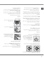
• If the top of the hob is higher than the cupboards,
the appliance must be installed at least 600 mm away
from them.
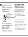
• If the cooker is installed underneath a wall cabinet,
there must be a minimum distance of 420 mm
between this cabinet and the top of the hob.
This distance should be increased to 700 mm if the
wall cabinets are flammable (see figure).
Ventilation opening
for comburent air
Increase in the gap
between the door and
the flooring
Fumes channelled
straight outside
Fumes channelled through
a chimney or a branched
flue system (reserved for
cooking appliances)

GB
8
• Do not position
blinds behind the cooker or less than 200 mm away
from its sides.
• Any hoods must be installed according to the
instructions listed in the relevant operating manual.
Levelling
If it is necessary to level the
appliance, screw the adjustable
feet into the places provided on
each corner of the base of the
cooker (see figure).
The legs* fit into the slots on the
underside of the base of the
cooker.
Electrical connection
Install a standardised plug corresponding to the load
indicated on the appliance data plate (see Technical
data table).
The appliance must be directly connected to the mains
using an omnipolar circuit-breaker with a minimum contact
opening of 3 mm installed between the appliance and the
mains. The circuit-breaker must be suitable for the charge
indicated and must comply with current national legislation
(the earthing wire must not be interrupted by the circuit-
breaker). The supply cable must be positioned so that it
does not come into contact with temperatures higher than
50°C at any point.
Before connecting the appliance to the power supply,
make sure that:
• The appliance is earthed and the plug is compliant with
the law.
• The socket can withstand the maximum power of the
appliance, which is indicated by the data plate.
• The voltage is in the range between the values
indicated on the data plate.
• The socket is compatible with the plug of the
appliance. If the socket is incompatible with the
plug, ask an authorised technician to replace it. Do
not use extension cords or multiple sockets.
Once the appliance has been installed, the power
supply cable and the electrical socket must be easily
accessible.
The cable must not be bent or compressed.
The cable must be checked regularly and replaced
by authorised technicians only.
The manufacturer declines any liability should
these safety measures not be observed.
HOOD
420
Min.
min.
650
mm. with hood
min.
700
mm. without hood
mm.
600
Min. mm.
420
Min. mm.
* Only available in certain models
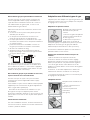
IF THE FITTED PLUG IS REMOVED*
The exible mains lead must be correctly connected as
below to a three pin plug of not less than 13 amp capacity.
If a B.S. 1363 fused plug is used, it must be tted with a
fuse which is approved to B.S. 1362.
Important: the wires in the mains lead are coloured in
accordance with the following code:
Green & Yellow - Earth
Blue - Neutral
Brown - Live
The power supply cable must be type H05VV-F
Green &
Yellow to
Earth
Brown
to Live
Blue to
Neutral
Cord
Clamp
3 Amp
Fuse
As the colours of the wires in the mains lead may not
correspond with the coloured markings identifying the
terminals in your plug, proceed as follows:
Connect the Green & Yellow wire to terminal marked “E”
or
or coloured Green or Green & Yellow.
Connect the Brown wire to the terminal marked “L” or
coloured Red.
Connect the Blue wire to the terminal marked “N” or
coloured Black.
FAILURE TO OBSERVE THE ACCIDENT-PREVENTION
REGULATIONS RELIEVES THE MANUFACTURER OF
ALL LIABILITY.
The appliance must not be installed behind
a decorative door in order to avoid overheating

Gas connection
Connection to the gas network or to the gas cylinder
may be carried out using a flexible rubber or steel hose,
in accordance with current national legislation and after
making sure that the appliance is suited to the type of gas
with which it will be supplied (see the rating sticker on
the cover: if this is not the case see below). When using
liquid gas from a cylinder, install a pressure regulator
which complies with current national regulations. To
make connection easier, the gas supply may be turned
sideways*: reverse the position of the hose holder with
that of the cap and replace the gasket that is supplied
with the appliance.
Check that the pressure of the gas supply is
consistent with the values indicated in the Table
of burner and nozzle specifications (see below).
This will ensure the safe operation and durability of
your appliance while maintaining efficient energy
consumption.
Gas connection using a flexible rubber hose
Make sure that the hose complies with current national
legislation. The internal diameter of the hose must
measure: 8 mm for liquid gas supply; 13 mm for
methane gas supply.
Once the connection has been performed, make sure
that the hose:
• Does not come into contact with any parts that reach
temperatures of over 50°C.
• Is not subject to any pulling or twisting forces and
that it is not kinked or bent.
• Does not come into contact with blades, sharp
corners or moving parts and that it is not
compressed.
IF A MOULDED PLUG IS FITTED
In the event of replacing a fuse in the plug supplied an ASTA
approved fuse to BS1362 must be tted.
NOTE: The fuse cover must be retted when changing the fuse.
In the event of losing the fuse cover the plug must not be used
until a replacement fuse cover has been obtained and tted. A
new fuse cover can be obtained from your local Electricity Board.
The colour of the correct replacement fuse cover is that of the
coloured marks or inserts in the base of the plug.
Make sure that the cable does not become trapped when
pushing the cooker into position.
Replacing the cable
Use a rubber cable of the type H05VV-F with a cross section
of 3 x 1.5 mm². The yellow-green earth wire must be 2 ÷ 3
cm longer than the other wires.
• Is easy to inspect along its whole length so that its
condition may be checked.
• Is shorter than 1500 mm.
• Fits firmly into place at both ends, where it will
be fixed using clamps that comply with current
regulations.
If one or more of these conditions is not fulfilled
or if the cooker must be installed according to the
conditions listed for class 2 - subclass 1 appliances
(installed between two cupboards), the flexible steel
hose must be used instead (see below).
Connecting a flexible jointless stainless steel pipe
to a threaded attachment
Make sure that the hose and gaskets comply with
current national legislation.
To begin using the hose, remove the hose holder on
the appliance (the gas supply inlet on the appliance is
a cylindrical threaded 1/2 gas male attachment).
Perform the connection in such a way that the hose
length does not exceed a maximum of 2 metres,
making sure that the hose is not compressed and does
not come into contact with moving parts.
Checking the tightness of the connection
When the installation process is complete, check the
hose fittings for leaks using a soapy solution. Never
use a flame.
GB
9
* Only available in certain models

10
GB
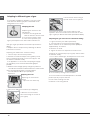
Adapting to different types of gas
It is possible to adapt the appliance to a type of gas
other than the default type (this is indicated on the
rating label on the cover).
Adapting the hob
Replacing the nozzles for the
hob burners:
1. Remove the hob grids and
slide the burners off their seats.
2. Unscrew the nozzles using
a 7 mm socket spanner (see
figure), and replace them with nozzles suited to the
new type of gas (see Burner and nozzle specifications
table).
3. Replace all the components by following the above
instructions in reverse.
Adjusting the hob burners’ minimum setting:
1. Turn the tap to the minimum position.
2. Remove the knob and adjust the regulatory screw,
which is positioned inside or next to the tap pin, until
the flame is small but steady.
If the appliance is connected to a liquid gas supply,
the regulatory screw must be fastened as tightly as
possible.
3. While the burner is alight, quickly change the position of
the knob from minimum to maximum and vice versa several
times, checking that the flame is not extinguished.
The hob burners do
not require primary air
adjustment.
Adapting the oven
Replacing the oven burner
nozzle:
1. Open the oven door fully
2. Pull out the sliding oven bottom (see diagram).
3. Remove the oven burner
after unscrewing the screws V
(see figure).
4. Unscrew the nozzle using a
special nozzle socket spanner
(see figure) or with a 7 mm socket spanner, and
replace it with a new nozzle that is suited to the new
type of gas (see Burner and nozzle specifications table).
Adjusting the gas oven burner’s minimum setting:
1. Light the burner (see Start-up and Use).
2. Turn the knob to the minimum position (MIN)
after it has been in the maximum position (MAX) for
approximately 10 minutes.
3. Remove the knob.
4. Tighten or loosen the adjustment screws on the
V
outside of the thermostat pin (see figure) until the flame
is small but steady.
In the case of natural gas, the adjustment screw must
be unscrewed by turning it anti-clockwise.
5. Turn the knob from the MAX position to the MIN
position quickly or open and shut
the oven door, making sure that
the burner is not extinguished.

GB
11
Adapting the grill
Replacing the grill burner nozzle:
1. Remove the oven burner
after loosening screw V (see
figure).
2. Unscrew the grill burner
nozzle using a special nozzle
socket spanner (see figure) or
preferably with a 7 mm socket
spanner, and replace it with a
new nozzle that is suited to the new type of gas (see
Burner and nozzle specifications table).
Be careful of the spark plug wires and the
thermocouple tubes.
The oven and grill burners do not require primary air
adjustment.
After adjusting the appliance so it may be used with
a different type of gas, replace the old rating label with
a new one that corresponds to the new type of gas
(these labels are available from Authorised Technical
Assistance Centres).
Should the gas pressure used be different (or vary
slightly) from the recommended pressure, a suitable
pressure regulator must be fitted to the inlet hose in
accordance with current national regulations relating to
“regulators for channelled gas”.
V
I
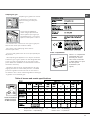
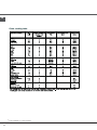
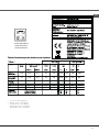
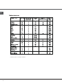
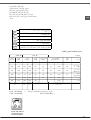
Table of burner and nozzle specifications
* At 15°C and 1013 mbar- dry gas
** Propane P.C.S. = 50,37 MJ/Kg
*** Butane P.C.S. = 49,47 MJ/Kg
Natural P.C.S. = 37,78 MJ/m
100
3,00
0,7
41
87 218
214
128
286
75
1,90
0,4
50
73
71
78
95
51
1,00
0,4
30
30
69
138
136
104
181
S
S
R
A
ACMK 6110/WH/3
ACMK 6110/IX/2
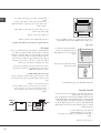
Lower compartment*
There is a compartment
underneath the oven
that may be used to
store oven accessories
or deep dishes. To open
the door pull it
downwards (
see
figure
).
ACMK 6110/IX/3

GB
12
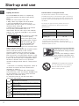
Practical advice on using the burners
For the burners to work in the most efficient way
possible and to save on the amount of gas consumed, it
is recommended that only pans that have a lid and a flat
base are used. They should also be suited to the size of
the burner.
To identify the type of burner, please refer to the
diagrams contained in the “Burner and nozzle
specifications”.
Start-up and use
On the models supplied with a reducer shelf,
remember that this should be used only for the
auxiliary burner when you use casserole dishes with a
diameter under 12 cm.0
WARNING! The glass lid can break
in if it is heated up. Turn off all the
burners and the electric plates
before closing the lid.
*
Only available in certain models.
Using the hob
Lighting the burners
For each BURNER knob there is a complete ring
showing the strength of the flame for the relevant
burner.
To light one of the burners on the hob:
1. Bring a flame or gas lighter close to the burner.
2. Press the BURNER knob and turn it in an
anticlockwise direction so that it is pointing to the
maximum flame setting (.
3. Adjust the intensity of the flame to the desired
level by turning the BURNER knob in an
anticlockwise direction. This may be the minimum
setting &, the maximum setting ( or any position
in between the two.
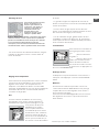
If the appliance is fitted with
an electronic lighting
device* (
see figure
), press
the ignition button, marked
with the symbol , then
hold the BURNER knob
down and turn it in an
anticlockwise direction, towards the maximum flame
setting, until the burner is lit.
Several models are equipped with an ignition device
which is built into the knob; in this case the
electronic ignition device* is present (
C
) but the
ignition button is not. Simply press the BURNER
knob and turn it in an anticlockwise direction so that
it is pointing to the maximum flame setting, until the
burner is lit. The burner may be extinguished when
the knob is released. If this occurs, repeat the
operation, holding the knob down for a longer period
of time.
If the flame is accidentally extinguished, switch off
the burner and wait for at least 1 minute before
attempting to relight it.
If the appliance is equipped with a flame failure
safety device*(X), press and hold the BURNER knob
for approximately 2-3 seconds to keep the flame
alight and to activate the device.
To switch the burner off, turn the knob until it
reaches the stop position •.
X
C
Burner ø Cookware diameter (cm)
Fast (R) 24 - 26
Semi Fast (S) 16 - 20
Auxiliary (A) 10 - 14
WARNING! The oven is provided with
a stop system to extract the racks and
prevent them from coming out of the
oven.(1)
As shown in the drawing, to extract
them completely, simply lift the racks,
holding them on the front part, and
pull (2).
Ideal for gentle cooking (e.g: rice, sauces, roasts, fish) with
liquids (water, wine, broth, milk)
Ideal for stewing ( for a long period of time) and thickening.
Creaming pasta,
Ideal for sautéing.
Cooking on a high flame and browning (roast, steaks,
escalopes, fish fillets, fried eggs.)
Ideal for grilling and browning, starting to cook, frying deep
frozen products.
Ideal for rapidly increasing the temperature of food to fast
boiling in the case of water or rapidly heating cooking liquids.

13
GB
Adjusting the temperature
To set the desired cooking temperature, turn the
OVEN control knob in an anticlockwise direction.
Temperatures are displayed on the control panel and
may vary between MIN (150°C) and MAX (250°C).
Once the set temperature has been reached, the oven
will keep it constant by using its thermostat.
Grill
To light the grill, bring a flame or gas lighter close to
the burner and press the OVEN control knob while
turning it in a clockwise direction until it reaches the
position. The grill enables the surface of food to be
browned evenly and is particularly suitable for roast
dishes, schnitzel and sausages.
Place the rack in position 4 or 5
and the dripping pan in position
1 to collect fat and prevent the
formation of smoke.
The grill is fitted with a safety
device and it is therefore
necessary to hold the OVEN control knob down for
approximately 6 seconds.
If the flame is accidentally
extinguished, switch off the
burner and wait for at least
1 minute before attempting
to relight the grill.
! When using the grill,
leave the oven door ajar,
positioning the deflector D
between the door and the
control panel (see figure) in
order to prevent the knobs from overheating.
Turnspit*
To operate the rotisserie (see diagram) proceed as
follows:
1. Place the dripping pan in position 1.
2. Place the rotisserie support in position 4 and insert
the spit in the hole provided on the back panel of the
oven.
3. Acitvate the function by pressing the TURNSPIT
button.
Oven light
The light may be switched on at any moment by
pressing the OVEN LIGHT button.
Timer*
To activate the Timer proceed as follows:
1. Turn the TIMER knob in a clockwise direction for
almost one complete revolution to set the buzzer.
2. Turn the TIMER knob in an anticlockwise direction
to set the desired length of time.
D
*
Only available in certain models.
Using the oven
The first time you use your appliance, heat the
empty oven with its door closed at its maximum
temperature for at least half an hour. Ensure that the
room is well ventilated before switching the oven off
and opening the oven door. The appliance may emit a
slightly unpleasant odour caused by protective
substances used during the manufacturing process
burning away.
Before operating the product, remove all plastic film
from the sides of the appliance.
Never put objects directly on the bottom of the
oven; this will avoid the enamel coating being
damaged. Only use position 1 in the oven when
cooking with the rotisserie spit.
Lighting the oven
To light the oven burner, bring
a flame or gas lighter close to
opening F (
see figure
) and
press the OVEN control knob
while turning it in an
anticlockwise direction until it
reaches the MAX position.
If, after 15 seconds, the burner is still not alight,
release the knob, open the oven door and wait for at
least 1 minute before trying to light it again.
The oven is fitted with a safety device and it is
therefore necessary to hold the OVEN control knob
down for approximately 6 seconds.
F
If the flame is accidentally extinguished, switch off
the burner and wait for at least 1 minute before
attempting to relight the oven.

GB
14
*
Only available in certain models.
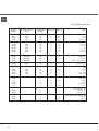
Oven cooking table

GB
15
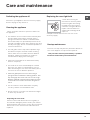
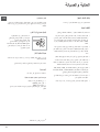
Switching the appliance off
Disconnect your appliance from the electricity supply
before carrying out any work on it.
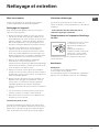
Cleaning the appliance
Never use steam cleaners or pressure cleaners on
the appliance.
• The stainless steel or enamel-coated external parts
and the rubber seals may be cleaned using a
sponge that has been soaked in lukewarm water
and neutral soap. Use specialised products for the
removal of stubborn stains. After cleaning, rinse well
and dry thoroughly. Do not use abrasive powders or
corrosive substances.
• The hob grids, burner caps, flame spreader rings
and burners may be removed to make cleaning
easier; wash them in hot water and non-abrasive
detergent, making sure all burnt-on residue is
removed before drying them thoroughly.
• Clean the terminal part of the flame failure safety
devices* frequently.
• The inside of the oven should ideally be cleaned
after each use, while it is still lukewarm. Use hot
water and detergent, then rinse well and dry with a
soft cloth. Do not use abrasive products.
•
Clean the glass part of the oven door using a
sponge and a non-abrasive cleaning product, then
dry thoroughly with a soft cloth. Do not use rough
abrasive material or sharp metal scrapers as these
could scratch the surface and cause the glass to
crack.
• The accessories can be washed like everyday
crockery, and are even dishwasher safe.
• Do not close the cover when the burners are alight
or when they are still hot.
replaced.
Replacing the oven light bulb
1. After disconnecting the
oven from the electricity mains,
remove the glass lid covering
the lamp socket (see figure).
2. Remove the light bulb and
replace it with a similar one:
voltage 230 V, wattage 25 W,
cap E 14.
3. Replace the lid and reconnect the oven to the
electricity supply.
Gas tap maintenance
Over time, the taps may become jammed or difficult to
turn. If this happens, the tap must be replaced.
This procedure must be performed by a qualified
technician authorised by the manufacturer.
Care and maintenance
Inspecting the oven seals
Check the door seals around the oven regularly. If
the seals are damaged, please contact your nearest
Authorised After-sales Service Centre. We recommend
that the oven is not used until the seals have been

GB
16
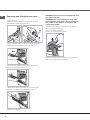
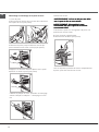
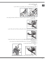
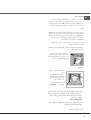
Removing and fitting the oven door:
1.Open the door
2.Make the hinge clamps of the oven door rotate
backwards completely (see photo)
3.Close the door until the clamps stop (the door will
remain open for 40° approx.) (see photo)
40°
4.Press the two buttons on the upper profile and
extract the profile (see photo)
5.Remove the glass sheet and do the cleaning as
indicated in chapter: "Care and maintenance".
6.Replace the glass.
WARNING! Oven must not be operated with inner
door glass removed!
WARNING! When reassembling the inner door
glass insert the glass panel correctly so that the
text written on the panel is not reversed and
can be easily legible.
7.Replace the profile, a click will indicate that the
part is positioned correctly.
8.Open the door completely.
9.Close the supports (see photo).
10.Now the door can be completely closed and the
oven can be started for normal use.

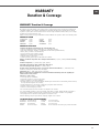
WARRANTY
Duration & Coverage
KIC products carry a full warranty service from the date of original retail purchase, supported by a qualified and
committed network of service partners nationwide. Any functional part which fails in normal home use will be
repaired or replaced, after a full assessment has been carried out by an Authorised Service Partner, free-of-charge
including the part itself and labour costs.
Evidence of the purchase (receipt), Model Number and Serial Number are required to obtain a free warranty service.
WARRANTY PERIOD
SOUTH AFRICA 2 years LESOTHO 2 years
BOTSWANA 2 years ZAMBIA 1 year
NAMIBIA 2 years ZIMBABWE 1 year
SWAZILAND 2 years MOZAMBIQUE 1 year
WARRANTY EXCEPTIONS
Conditions and damages resulting from any of the following cases:
• Improper installation, delivery or maintenance (i.e., pump filter cleaning);
• Any repair, modification, alteration, or adjustment not authorised by the Manufacturer;
• Misuse, abuse, accidents or unreasonable use;
• Incorrect electric current, voltage or supply;
• Damages due to voltage peaks or lightening;
• Improper settings of any control;
• Product previously repaired by non-authorised Service Partner.
Damage on aesthetic components due to transport and movement (i.e., dents, scratches) are not covered by
warranty.
Aesthetic components (i.e., handles, lamps, glass, plastics).
Light bulbs, water filter, air filter, carbon filter, rubber hoses.
Accessories and glass made optional (i.e., shelves, plates).
Products used for non-domestic purpose or located in commercial environment (i.e., restaurants, hotels,
hairdressers, laundry shops, butcher shops and garage).
Installation cost (i.e., water, power and gas connection).
Where a product has been returned due to incorrect information furnished by the dealer regarding the
features and use of the product.
Assistance or service call to:
• Correct any improper installation;
• Instruct the consumer on proper product usage;
• Transport appliance to the service workshop;
• No failure found (in case of functional failures claimed by the consumer and not found during technician check,
the repair will be charged to the consumer);
• Periodic maintenance or the cleaning of water filter, pump filter and air duct filter;
• Removal of transport support or fixation screws;
• Settle of feet and setting of gas nozzles.
Cost of the above-mentioned service call has to be charged to the consumer.
In no event shall KIC be liable for any consequential, either direct or indirect, damages whether foreseeable or
unforeseeable, resulting from improper usage or maintenance of the appliance as well as for any damages
consequently to the non-observance of the appliance’s instruction for use.
After the warranty period, all repairs will be completely charged to the consumer.
CUSTOMER CONTACT CENTRE NUMBERS
South Africa Tel: 0860 884 402 Swaziland Tel: 2404 5700/82
Mozambique Tel: 21 305 455/6 Lesotho Tel: +27 11 663 5479
Botswana Tel: 318 6630/1 Zambia Tel: 211 350 380
Namibia Tel: 061 40 2144/5 Zimbabwe Please contact the store where your purchase was made
WARRANTY Duration & Coverage
GB
17

18
FR
Conservez ce mode d’emploi pour pouvoir le
consulter à tout moment. En cas de vente, de
cession ou de déménagement, veillez à ce qu’il suive
l’appareil.
Lisez attentivement les instructions : elles contiennent
des conseils importants sur l’installation, l’utilisation et
la sécurité de votre appareil.
L’installation de l’appareil doit être effectuée par
un professionnel du secteur conformément aux
instructions du fabricant.
N’importe quelle opération de réglage, d’entretien,
etc., doit être effectuée après avoir débranché la prise
de la cuisinière.
Conditions réglementaires d’installation
Le raccordement gaz devra être fait par un
professionnel qualifié qui assurera la bonne
alimentation en gaz et le meilleur réglage de la
combustion des brûleurs. Ces opérations d’installation,
quoique simples, sont délicates et
primordiales pour que votre cuisinière vous rende
le meilleur service. L’installation doit être effectuée
conformément aux textes réglementaires et règles de
l’art en vigueur, notamment:
• Arrêté du 2 août 1977. Règles techniques et de
sécurité applicables aux installations de gaz
combustibles et d’hydro-carbures liquéfiés situées
à l’intérieur des bâtiments d’habitation et de leur
dépendances.
• Norme DTU P45-204. Installations de gaz
(anciennement DTU n° 61-1-installations de gaz -
Avril 1982 + additif n°1 Juillet 1984).
• Règlement sanitaire départemental.
Aération des locaux
L’appareil doit être installé dans des locaux qui sont
aérés en permanence, selon les prescriptions des
Normes en vigueur dans le pays d’installation. Il est
indispensable que la pièce où l’appareil est installé
dispose d’une quantité d’air égale à la quantité d’air
comburant nécessaire à une bonne combustion du
gaz (le flux d’air doit être d’au moins 3 m
3
/h par kW de
puissance installée).
Les prises d’air, protégées par des grilles, doivent
disposer d’un conduit d’au moins 2 cm2 de section
utile et dans une position qui leur évite tout risque
d’être bouchées accidentellement, même partiellement
(voir figure A).
Ces ouvertures doivent être agrandies de 100%
(surface minimale 2 cm2) en cas d’appareils
dépourvus du dispositif de sécurité de flamme et
quand l’afflux de l’air provient de manière indirecte de
pièces voisines (voir figure B) – à condition qu’il ne
s’agisse pas de parties communes du bâtiment, de
chambres à coucher ou de locaux à risque d’incendie
– équipées d’un conduit d’aération avec l’extérieur
comme décrit plus haut.
A B
Après une utilisation prolongée de l’appareil, il est
conseillé d’ouvrir une fenêtre ou d’augmenter la vitesse
de ventilateurs éventuels.
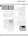
Evacuation des fumées de combustion
La pièce doit prévoir un système d’évacuation vers
l’extérieur des fumées de combustion réalisé au moyen
d’une hotte reliée à une cheminée à tirage naturel ou
par ventilateur électrique qui entre automatiquement
en fonction dès qu’on allume l’appareil (voir figures).
Les gaz de pétrole liquéfiés, plus lourds que l’air,
se déposent et stagnent dans le bas. Les locaux
qui contiennent des bouteilles de G.P.L doivent
donc prévoir des ouvertures vers l’extérieur afin de
permettre l’évacuation du gaz par le bas en cas de
fuites accidentelles. Ne pas installer ou entreposer de
bouteilles de GPL, vides ou partiellement pleines, dans
des locaux qui se trouvent en sous-sol (caves etc.). Ne
gardez dans la pièce que la bouteille que vous êtes en
train d’utiliser, loin de sources de chaleur (fours, feux de
bois, poêles etc.) qui pourraient amener sa température
à plus de 50°C.
A
Evacuation par cheminée ou
conduit de fumée ramifié (réservé
aux appareils de cuisson)
Installation
Local adjacent
Local à ventiler
Ouverture de ventilation
pour l’air comburant
Agrandissement de la
fissure entre la porte et
le sol
Evacuation
directement à
l’extérieur

FR
19
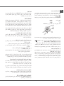
Positionnement et nivellement
L’appareil peut être installé à côté de meubles dont la
hauteur ne dépasse pas celle du plan de cuisson.
Assurez-vous que le mur en contact avec la paroi
arrière de l’appareil est réalisée en matériel ignifuge
résistant à la chaleur (T 90°C).
Pour une installation correcte :
• installez cet appareil dans une cuisine, une salle
à manger ou un studio (jamais dans une salle de
bains);
• si le plan de cuisson de la cuisinière dépasse le
plan de travail des meubles, ces derniers doivent
être placés à au moins 200 mm de l’appareil;
• si la cuisinière est
installée sous un
élément suspendu,
il faut que ce dernier
soit placé à au moins
420mm de distance du
plan. Il faut prévoir une
distance de 700mm si
les éléments suspendus
sont inflammables (voir
figure);
• ne placez pas de rideaux derrière la cuisinière ou
sur ses côtés à moins de 200 mm de distance;
• pour l’installation de hottes, conformez-vous aux
instructions de leur notice d’emploi.
Nivellement
Pour mettre l’appareil bien
à plat, vissez les pieds
de réglage fournis aux
emplacements prévus aux
coins à la base de la cuisinière
(voir figure).
Montage des pieds* par
encastrement sous la base.
Raccordement électrique
Montez sur le câble une prise normalisée pour la
charge indiquée sur l’étiquette des caractéristiques
(voir tableau des caractéristiques techniques).
En cas de raccordement direct au réseau, il faut
intercaler entre l’appareil et le réseau un interrupteur
à coupure omnipolaire ayant au moins 3 mm
d’écartement entre les contacts, dimensionné à la
charge et conforme aux normes en vigueur (le fil de
terre ne doit pas être interrompu par l’interrupteur). Le
câble d’alimentation ne doit atteindre, en aucun point,
des températures dépassant de 50°C la température
ambiante.
Avant de procéder au branchement, assurez-vous que :
• la prise est bien munie d’une terre conforme à la loi;
• la prise est bien apte à supporter la puissance
maximale de l’appareil, indiquée sur la plaquette
signalétique;
• la tension d’alimentation est bien comprise entre les
valeurs indiquées sur la plaquette signalétique;
• la prise est bien compatible avec la fiche de
l’appareil. Si ce n’est pas le cas, remplacez la prise
ou la fiche, n’utilisez ni rallonges ni prises multiples.
Après installation de l’appareil, le câble électrique et
la prise de courant doivent être facilement accessibles
Le câble ne doit être ni plié ni excessivement écrasé.
Le câble doit être contrôlé périodiquement et ne peut
être remplacé que par un technicien agréé.
Nous déclinons toute responsabilité en cas de non
respect des normes énumérées ci-dessus.
*N’existe que sur certains modèles
HOOD
420
Min.
min.
650
mm. with hood
min.
700
mm. without hood
mm.
600
Min. mm.
420
Min. mm.
N’installez pas l’appareil derrière
une porte décorative afin
d’éviter toute surchauffe.

FR
20
Raccordement gaz
Pour raccorder l’appareil au réseau de distribution
du gaz ou à la bouteille de gaz utilisez un tuyau
flexible en caoutchouc ou en acier, conformément
à la réglementation en vigueur. Assurez-vous
auparavant que l’appareil est bien réglé pour le type
de gaz d’alimentation utilisé (voir étiquette sur le
couvercle : autrement voir ci-dessous). Si l’alimentation
s’effectue avec du gaz liquide en bouteille, utilisez
des régulateurs de pression conformes à la
réglementation en vigueur dans le pays. Pour simplifier
le raccordement, l’alimentation du gaz est orientable
latéralement* : inversez l’about annelé avec le bouchon
de fermeture et remplacez le joint d’étanchéité (fourni
avec l’appareil).
Pour un fonctionnement en toute sécurité, pour
un meilleur emploi de l’énergie et une plus longue
durée de vie de l’appareil, vérifiez que la pression
d’alimentation respecte bien les valeurs indiquées
dans le tableau Caractéristiques des brûleurs et des
injecteurs (voir ci-dessous).
Vert &
jaune pour
la terre
Marron pour la
ligne sous tension
Bleu pour
Neutre
Collier de
cordon
Fusible de
3 Ampères
SI LA FICHE ÉQUIPÉE EST ENLEVÉE
Le cordon d'alimentation flexible doit être
correctement connecté comme suit à une
fiche à trois broches de pas moins de 13
ampères.
Si vous utilisez une fiche à fusible
B.S. 1363, elle doit être équipée d'un fusible
conforme à B.S. 1362.
Important : les fils du cordon d'alimentation
sont colorés selon le code suivant :
Vert & jaune - Terre
Bleu - Neutre
Marron - Phase
Le câble d'alimentation doit être
de type H05VV-F
Dans le cas où les couleurs des fils du
cordon d'alimentation ne correspondent
pas aux marques colorées identifiant les
bornes de votre fiche, procédez comme suit :
Connectez le fil vert et jaune à la borne
marquée « E », ou de couleur
verte ou vert et jaune.
Connectez le fil marron à la borne
marquée « L » ou de couleur rouge.
Connectez le fil bleu à la borne
marquée « N » ou de couleur noire.
LE NON RESPECT DES INSTRUCTIONS
DE PRÉVENTION D'ACCIDENTS LIBÈRE LE
FABRICANT DE TOUTE RESPONSABILITÉ.
SI UNE FICHE MOULÉE EST ÉQUIPÉE
En cas de remplacement d'un fusible dans
la fiche fournie, un fusible ASTA conforme à
la norme BS1362 doit être installé.
REMARQUE : Le couvercle du fusible doit
être repositionné lors du changement du fusible.
En cas de perte du couvercle du fusible,
la prise ne doit pas être utilisée jusqu'à ce
qu'un couvercle de remplacement soit obtenu
et fixé. Un nouveau couvercle de fusible peut
être obtenu auprès de votre agence locale d'électricité.
La couleur du bon couvercle du fusible de
rechange correspond aux marques colorées
ou aux douilles dans le fond du bouchon.
Assurez-vous que le câble ne soit pas coincé
lors du positionnement de la cuisinière.
Remplacement du câble
Utilisez un câble en caoutchouc de type
H05VV-F avec une section transversale
de 3 x 1,5 mm ². La fiche de terre jaune-verte
doit être de 2 ÷ 3 cm plus longue que les autres
fiches.
*N’existe que sur certains modèles
La page est en cours de chargement...
La page est en cours de chargement...
La page est en cours de chargement...
La page est en cours de chargement...
La page est en cours de chargement...
La page est en cours de chargement...
La page est en cours de chargement...
La page est en cours de chargement...
La page est en cours de chargement...
La page est en cours de chargement...
La page est en cours de chargement...
La page est en cours de chargement...
La page est en cours de chargement...
La page est en cours de chargement...
La page est en cours de chargement...
La page est en cours de chargement...
La page est en cours de chargement...
La page est en cours de chargement...
La page est en cours de chargement...
La page est en cours de chargement...
La page est en cours de chargement...
La page est en cours de chargement...
La page est en cours de chargement...
La page est en cours de chargement...
-
 1
1
-
 2
2
-
 3
3
-
 4
4
-
 5
5
-
 6
6
-
 7
7
-
 8
8
-
 9
9
-
 10
10
-
 11
11
-
 12
12
-
 13
13
-
 14
14
-
 15
15
-
 16
16
-
 17
17
-
 18
18
-
 19
19
-
 20
20
-
 21
21
-
 22
22
-
 23
23
-
 24
24
-
 25
25
-
 26
26
-
 27
27
-
 28
28
-
 29
29
-
 30
30
-
 31
31
-
 32
32
-
 33
33
-
 34
34
-
 35
35
-
 36
36
-
 37
37
-
 38
38
-
 39
39
-
 40
40
-
 41
41
-
 42
42
-
 43
43
-
 44
44


Whirlpool ACMK 6110 / WH / 3 Mode d'emploi
- Catégorie
- Plaques de cuisson
- Taper
- Mode d'emploi
- Ce manuel convient également à
dans d''autres langues
Documents connexes
-
Indesit I6TG1G(X)/EX Mode d'emploi
-
Whirlpool KN6C11(W)/EX S Mode d'emploi
-
-
Ariston A6GG1F (X) EX Mode d'emploi
-
Whirlpool ACMK 6123/WH Mode d'emploi
-
-
-
-