Vari-Lite VL800 BEAMLINE Guide de démarrage rapide
- Taper
- Guide de démarrage rapide

VL800 BEAMLINE
QUICK START GUIDE

1 88-105-7290-00
Introduction
About This Guide
This Quickstart Guide is intended for a knowledgeable user to unpack, install, and use the VL 800 BeamLine luminaire in
a short time period. For the complete manual in PDF format, please visit our web site at: www.vari-lite.com and click the
user manual download link on the product downloads page. The complete manual provides you all information related to
accessories, menu structures, DMX channel mapping/modes, and care for your new luminaire.
Read this manual in its entirety before operating luminaire. Keep this guide for future reference.
WARNING: It is important to read ALL accompanying safety and installation instructions to avoid damage to the product and potential injury to yourself or
others.
AVERTISSEMENT: Il est important de lire toutes les instructions de sécurité et d'installation d'accompagnement pour éviter d'endommager le
produit et les risques de blessures à vous-même ou les autres.
Notes:
• For complete product description, features, and specifications, refer to product datasheet on the Vari-
Lite web site at www.vari-lite.com.
• For power requirements, refer to “Current vs. Voltage” on page 14.
• VL 800 Luminaires accept glass gobos only. Use of metal gobos will void the luminaire’s warranty.
Additional Documentation
For more information on installing DMX512 control systems, the following publication is available for purchase from the
United States Institute for Theatre Technology (USITT), “Recommended Practice for DMX512: A Guide for Users and
Installers, 2nd edition” (ISBN: 9780955703522). USITT Contact Information:
USITT
315 South Crouse Avenue, Suite 200
Syracuse, New York 13210-1844 USA
Phone: 800-938-7488 or +1-315-463-6463
Fax: 866-398-7488 or +1-315-463-6525
Web Site: www.usitt.org
Customer Service
Our Goal
At Vari-Lite, we are committed to providing you the highest quality in customer service. Our comprehensive resources are
available to help your business succeed and ensure you get the full benefit of being a Vari-Lite customer. Whether your
needs are telephone troubleshooting assistance, product training or technical service, our full-time staff of experienced
professionals are on-hand to provide support.
How to Reach Us
For assistance in your area, call the dealer from which your product was purchased.
or Contact an Authorized Service Center
or Contact the Customer Service Department, 7am - 6pm CST Monday through Friday, at the following:
phone:1-877-VARI-LITE (1-877-827-4548) or +1-214-647-7880
e-mail: entertainment.service@signify.com
Note: Performing maintenance procedures may void the product warranty. Refer to the Vari-Lite Limited Warranty
card included in the product shipping package for more information. For all service and maintenance issues, please
contact your local Authorized Dealer or Service Center.

88-105-7290-00 2
Additional Resources
For additional resources and documentation on this product, please visit our website at www.vari-
lite.com and follow the Support link.
Document Number: 02.1710.0022
Version as of: 6 March 2018
VL 800 BeamLine luminaire QuickStart Guide
©2019 Signify Holdings. All rights reserved.
Compliance & Safety Notices
Compliance
SAFETY Standards
We, Vari-Lite, 10911 Petal Street, Dallas, Texas 75238 declare under our responsibility for the products contained herein are
in conformity with the essential requirements of the following European Directives and Safety standards for United States
and Canada.
EN 60598-1:2015
EMC Standards
This equipment has been tested and found to comply with the limits for a Class B digital device pursuant to Part 15 of FCC
Rules. These limits are designed to provide reasonable protection against harmful interference when this equipment is
operated in a commercial environment. This equipment generates, uses, and can radiate radio frequency energy and, if not
installed and used in accordance with Vari-Lite system, service, and safety guidelines, may cause harmful interference to
radio communications.
47CFR FCC Part 15 Class B 2017
EN 61547:2009
EN 55015:2013
ICES-003:2016
Safety Notice
It is extremely important to read ALL safety information and instructions provided in this manual and any accompanying
documentation before installing and operating the products described herein. Heed all cautions and warnings during
installation and use of this product.
Safety symbols used throughout this manual are as follows:
GENERAL INFORMATION PERTAINING TO PROTECTION AGAINST ELECTRICAL SHOCK, FIRE, EXPOSURE
TO EXCESSIVE UV RADIATION, AND INJURY TO PERSONS CAN BE FOUND BELOW.
WARNING:
INSTRUCTIONS FOR CONTINUED PROTECTION AGAINST FIRE
1. VARI❋LITE luminaires have been designed for use with specific lamp types. The VL 800 BeamLine Luminaire requires a certain type
of lamp (see
“Replacement Items/Accessories” on page 8 for all lamp types). Installing another type or unapproved lamp may
be hazardous.
CAUTION advising of potential damage to product.
WARNING advising of potential injury or death to persons.

VARI❋LITE - VL 800 BEAMLINE LUMINAIRE QUICKSTART GUIDE
3 88-105-7290-00
2. Luminaires may be mounted on any type of surface as long as mounting instructions are followed. See instructions detailed in this
manual.
3. Note distance requirement from combustible materials or illuminated objects for VARI❋LITE luminaires.
WARNING:
INSTRUCTIONS FOR CONTINUED PROTECTION AGAINST ELECTRICAL SHOCK
1. VARI❋LITE luminaires are designed for dry locations only. Exposure to rain or moisture may damage luminaire.
2. Disconnect power before servicing any VARI❋LITE equipment.
3. Servicing to be performed by qualified personnel only.
WARNING:
INSTRUCTIONS FOR CONTINUED PROTECTION AGAINST EXCESSIVE EXPOSURE TO
UV RADIATION
1. Many VARI❋LITE luminaires use a lamp that produces UV radiation. DO NOT look directly at lamp.
2. It is hazardous to operate luminaires without lens or shield. Shields, lenses, or ultraviolet screens shall be changed if they have become
visibly damaged to such an extent that their effectiveness is impaired. For example, by cracks or deep scratches. Replace any cracked or
protective shields.
WARNING:
INSTRUCTIONS FOR PROTECTION AGAINST INJURY TO PERSONS
1. Exterior surfaces of the luminaire will be hot during operation. Use appropriate safety equipment (gloves, eye protection, etc.) when
handling and adjusting hot equipment and components.
2. Luminaires will have a hot lamp when operating. Disconnect power and allow lamp to cool before replacing.
3. Arc lamps emit ultraviolet radiation which can cause serious skin burn and eye inflammation. Additionally, arc lamps operate under
high pressure at very high temperatures. Should the lamp break, there can exist a danger of personal injury and/or fire from broken lamp
particles being discharged.
4. Wear eye protection when relamping.
5. Appropriate safety equipment (gloves, eye protection) should be used when handling damaged lamps.
6. If lamp is touched with bare hands, clean lamp with denatured alcohol and wipe with lint-free cloth before installing or powering up the
luminaire.
7. The lamp shall be changed if it has become damaged or thermally deformed.
WARNING:
RF INTERFERENCE
This is a Class A product. In a domestic environment this product may cause radio interference, in which case, the user may
be required to take adequate measures.
Notes de sécurité
Avant de procéder à l’installation des produits décrits dans ce guide et de les mettre en marche, il est extrêmement important
de lire TOUS les renseignements et TOUTES les directives de sécurité contenues dans ce guide ainsi que toute documentation
jointe. Tenir compte de tous les avertissements et suivre toutes les précautions pendant l’installation et l’utilisation de cet
appareil.
Les symboles de sécurité utilisés dans ce guide sont les suivants :
CETTE SECTION CONTIENT DES INFORMATIONS GÉNÉRALES POUR SE PROTÉGER CONTRE LES
DÉCHARGES ÉLECTRIQUES, LES INCENDIES, L’EXPOSITION EXCESSIVE AUX RAYONS UV ET TOUT AUTRE
ACCIDENT POUVANT ENTRAÎNER DES BLESSURES.
ATTENTION Ce symbole annonce que l’appareil risque d’être endommagé.
AVERTISSEMENT Ce symbole annonce qu’il y a risque d’accident grave ou même fatal.

88-105-7290-00 4
AVERTISSEMENT:
DIRECTIVES POUR SE PROTÉGER CONTRE LES INCENDIES
1. Les luminaires VARI❋LITE ont été conçus pour être utilisés uniquement avec certaines type de lampes. Vérifier le type de lampe avant
de remplacer les lampes. L’installation d’un autre type de lampe peut poser un danger.
2. Les luminaires peuvent être fixés sur tout type de surface tant que les directives de montage sont respectées. Voir les explications
détaillées dans ce guide.
3. Vérifier la distance à respecter entre les matériaux combustibles ou les objets illuminés et les luminaires VARI❋LITE.
AVERTISSEMENT:
DIRECTIVES POUR SE PROTÉGER CONTRE LES DÉCHARGES ÉLECTRIQUES
1. Les luminaires VARI❋LITE sont conçus pour une utilisation au sec uniquement. Une exposition à la pluie et à l’humidité risque
d’endommager le luminaire.
2. Débrancher l’appareil avant de procéder à la révision de tout matériel VARI❋LITE.
3. Les révisions doivent être effectuées uniquement par des personnes qualifiées.
AVERTISSEMENT:
DIRECTIVES POUR SE PROTÉGER CONTRE UNE EXPOSITION EXCESSIVE AUX RAY-
ONS UV
1. Plusieurs luminaires VARI❋LITE utilisent une lampe qui produit des rayons UV. NE PAS fixer son regard sur la lampe.
2. L’utilisation des luminaires sans lentille ou blindage pose des risques. Tous blindages, lentilles ou écrans ultraviolet visiblement
endommagés au point que leur efficacité en est affectée doivent être remplacés, par exemple s’il y a des fissures ou de profondes
rayures.
AVERTISSEMENT: DIRECTIVES POUR SE PROTÉGER CONTRE LES ACCIDENTS
POUVANT ENTRAÎNER DES BLESSURES
1. Les surfaces externes du luminaire deviennent brûlantes quand l’appareil est en marche. Pour manœuvrer ou ajuster des appareils
brûlants et leurs composants, se protéger suffisamment (gants, protection pour les yeux, etc.).
2. La lampe du luminaire est brûlante lorqu’il est en marche. Débrancher le courant et attendre que la lampe ait refroidi avant de la
remplacer.
3. Les lampes à arc émettent des rayons ultraviolets pouvant causer de graves brûlures sur la peau et une inflammation des yeux. De plus,
les lampes à arc fonctionnent sous haute tension à de très hautes températures. Si la lampe se casse, les particules de la lampe cassée
peuvent causer blessures et/ou incendie en s’éparpillant.
4. Se protéger les yeux pour remplacer la lampe.
5. Utiliser des appareils de protection appropriés (gants, protection des yeux) pour manier des lampes endommagées.
6. Si la lampe a été touchée avec des mains nues, la nettoyer avec de l’alcool dénaturé et l’essuyer avec un chiffon non-pelucheux avant
d’installer ou de brancher le luminaire.
7. Si la lampe a été endommagée ou a reçu une déformation thermique, elle doit être remplacée.
AVERTISSEMENT: INTERFÉRENCE RF
Cet appareil est de Classe A. Dans un environnement domestique, cet appareil peut causer des interférences radio, et si c’est
le cas, l’utilisateur peut avoir à prendre des mesures adéquates.
Other
Operational Temperature / Température de fonctionnement
• The VL 800 BeamLine luminaire has one operational mode. Refer to Table 1-1, “VL 800 Environmental Operational
Temperatures” for information on environment temperature ranges associated with this mode.
• Le VL 800 BeamLine luminaire a un mode opérationnel. Reportez-vous à Table 1-1, “VL 800 Environmental
Operational Temperatures” pour des informations sur les plages de température environnementales associées à ce
mode.
Table 1-1: VL 800 Environmental Operational Temperatures
Minimum to Maximum Environmental Temperature
CF
0
o
to 40
o
-4
o
to 122
o

5 88-105-7290-00
About the VL 800 BeamLine Luminaire
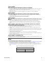
Included Items
The following illustration shows all items included with the luminaire:
Figure 1: VL 800 BeamLine luminaire Included Items
Replacement Items / Accessories
The following optional and/or replacement items can be ordered directly from your Authorized VARI❋LITE Dealer. When
ordering, please order by the Vari-Lite part number.
Note: Please check with Vari-Lite or Authorized Vari-Lite Dealer for availability on accessories.
Vari-Lite Part No. Accessory
AC Input Cable, Neutrik® powerCON® True1 with Twist Lock (Male), 250V, 1 Meter
Luminaire Programming Software
Safety Cable Assembly
DMX Termination Connector Assembly
Truss Hook, Mega-Clamp, Round and Square
Truss Hook, Mega-Claw for 2” Round Tube
Neutrik® powerCON TRUE1
AC Input Connector
Warranty Card
Product
Registration
Product Support
Sheet
QuickStart Guide
Included Items
(this document)

88-105-7290-00 6
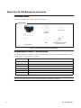
Connecting Power and Data
Connecting Power
The luminaire requires standard AC power distribution from 200-240 VAC, 50/60 Hz. Current required depends on the AC
supply voltage and product model. Refer to “Current vs. Voltage” on page 7 for all models covered in this manual.
Note: The mating Neutrik® powerCON® True1 connector is supplied; however, you will need to purchase or construct a
cable appropriate for your application. Available power input cables is found in “Replacement Items/Accessories” on page 8.
Figure 2: Power Connector
Depending on the application, the luminaire’s AC input cable may require a different connector. If required, install a new
connector meeting your requirements using the following wire color code reference:
WARNING: DO NOT connect to three-phase service in countries with 240 volt power. AVERTISSEMENT: NE PAS se
connecter au service en trois phases dans les pays avec puissance de 240 volts.
For single-phase power at 240 volts RMS:
For three-phase power at 200 volts RMS:
WARNING: It is not recommended to power any VARI❋LITE luminaire from a dimmer - even in 'NONDIM' mode. Dimmer
and non-dim modules are not suitable sources of power because their output modifies the AC wave form. This may work for
a short time, but will eventually result in power problems, luminaire mis-operation and/or failure and may void the
luminaire’s warranty. AVERTISSEMENT: Il n'est pas recommandé pour alimenter un luminaire VARI❋LITE d'un gradateur
- même en mode 'NONDIM’. Modules de gradation et non sombres ne sont pas des sources appropriées de pouvoir parce que
Wire* Connection
Green/Yellow AC Ground
Blue AC Neutral
Brown AC Line
* International (Harmonized) Standard
Connection Pin
AC Neutral X
AC Line Y
Ground (Earth) G
Connection Pin
Phase 1 X
Phase 2 Y
Ground (Earth) G
AC Power Input
3-Pole Neutrik® powerCON TRUE1 for AC Input Power
Neutrik® powerCON TRUE1
AC Input Connector
X
Y
G
X
Y
G

7 88-105-7290-00
leur production modifie la forme d'onde AC. Cela peut fonctionner pendant une courte période, mais finira par entraîner des
problèmes d'alimentation, luminaires mauvais fonctionnement et / ou l'échec et peut annuler la garantie de l'appareil.
Current vs. Voltage
Table 1-2, VL 800 BeamLine Luminaire - Current vs. Voltage (230W LED) provides the luminaire’s current draw at
specific voltages. Total Luminaire Current is calculated with the lamp on and all motors sequencing.
WARNING: It is the responsibility of the user to adequately protect supply source with a correct size and type circuit breaker
and not overload circuits. AVERTISSEMENT: Il est de la responsibilité de l'utilisateur de protéger adéquatement la source
d'alimentation avec une taille correcte et le disjoncteur de type et surchargez pas les circuits.
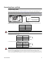
Connecting Data
A maximum of 32 luminaires may be connected in any one DMX data link.
Note: This maximum limit applies to the luminaire "daisy chain" only. Your system or console may require fewer luminaires
on a single data link path. Consult your console documentation for more information.
To connect power and data:
Step 1. Connect data cable from console to first luminaire in chain at DATA IN connector.
Step 2. If required, connect additional data cables from DATA THRU connectors to DATA IN connectors of remaining
luminaires in link.
Table 1-2: VL 800 BeamLine Luminaire - Current vs. Voltage (230W LED)
AC Voltage @ 60Hz Total Luminaire Current (Motor + Lamp Current)
100V 2.8A
110 V 2.6A
120V 2.3A
130V 2.1A
200V 1.4A
210V 1.3A
220 V 1.25A
230 V 1.2A
240 V 1.15A

88-105-7290-00 8
Step 3. At last luminaire in link, install male termination connector at DATA THRU connector. (Luminaires and other
devices on the same DMX chain may not function properly without termination.)
Figure 3: Data Link
Step 4. Connect AC Input Cable connector to power input source.
Step 5. Dress AC input and data cables and secure them so that they will not interfere with luminaire head and yoke
movement.
Installation Procedures
Floor Mounting the Luminaire
All luminaires included in this manual are designed to sit directly on its base in a floor installation application. When used in
this type of application, be sure to leave enough space around the luminaire to allow proper, uninterrupted airflow for cooling
and movement.
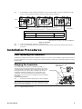
Hanging the Luminaire
The VL 800 BeamLine luminaire can be hung horizontally or
vertically from any structure designed to work with the type of load
created by this moving luminaire. Two mounting truss hooks or other
mounting hardware are required. Many compatible truss hooks are
available from different manufacturers for your particular needs.
A minimum of two hooks per luminaire is required. If mounting
method does not use truss hooks, two attachment points, per luminaire,
are required.
Install mounting hardware:
Step 1. Install truss hooks and omega clamps as shown in
Figure 4.
Note: Various types of truss hooks can be used. The Mega Claw truss
hook (as shown in the example above) as well as many other standard
hooks, can be ordered separately.
Step 2. Tighten hardware securely.
VL 800 BeamLine Luminaire Channel Requirements*
*As set by the luminaire’s menu system.
DMX512 Channels Description Menu Display
23 Channels 16-Bit Mode (default) 16
**DMX terminator required for last fixture on DMX line.
AC In
Termination**
Data In
Data Thru Data Thru
Mega Claw Truss Hook
(not provided)
Figure 4: Truss Hook Installation
Omega Clamp

9 88-105-7290-00
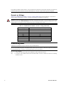
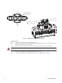
Figure 5: Installing Brackets on Luminaire Enclosure
Installing in Truss:
Step 1. Using two people, lift luminaire into mounting position.
Step 2. Secure in place with truss hooks. Ensure truss hook hardware that locks hook in place (e.g. wing bolt) is properly
tightened and that luminaire is fully supported.
Step 3. Attach safety cable by looping it at least once around safety cable anchor point rod (refer to
Figure 5).
CAUTION: Install a safety chain/cord that can hold at least 10 times the weight of the fixture. Never use the carrying handles
for attachment.
Step 4. Make sure tilt and pan locks are disengaged so luminaire moves freely.
Step 5. Connect power and data cables according to procedure given in “Connecting Data” on page 7.
A1
A2
safety chain/cord
attachment point

88-105-7290-00 10
Menu Operation
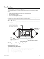
LCD Display and Menu System
The VL 800 BeamLine luminaire’s LCD Display and Menu System provides local control for accessing the following
settings:
• Address – to set the DMX address
• Configure – various parameter settings, set luminaire ID
• Fixture – fixture status, recalibrate, reboot, software version, view fixtures hours, etc.
• DMX – change the map, set address
• Service – password protected factory service menu
• Manual – manual control of parameters
• Test – test functions of parameters
The menu system is controlled at the Menu Display available at the enclosure input panel. If there are multiple luminaires in
a system, any settings or changes would need to be made at each LCD Menu as desired.
Menu Controls
The menu system is controlled by an OK (Enter), ESC (Escape), and four arrow () buttons. These buttons function
are shown in Figure 6.
Figure 6: Menu Control
LCD Display and Menu System Operation
The LCD Display Menu system consists of several categories. Use the Menu Buttons to access and make changes to the menu
items. When the desired menu item is reached, press the desired Menu Button to display the menu options and to navigate and
configure the menu options as required.
To navigate and access menu settings/selections:
Step 1. Make sure unit is powered and turned on.
Step 2. Press [ESC] to access menu categories.
Step 3. Use four Arrow () buttons to navigate through the various options and settings.
Step 4. Once menu item is reached, press OK [Enter] to access the menu item parameters.
Step 5. Make changes to parameters as desired.
Step 6. Press OK [Enter] button to accept changes.
VL 800 BeamLine
SQU
CURVE
NO
ERRORS
16G1
MAP
001
ADDR
LCD Display
OK (Enter) Button
To Select or Change a
Setting or Data Value
Escape (ESC)
Used to Access Main Menu Parameters,
Exit, or Return to Previous Menu Item
Arrow Keys (Up/Down/Left/Right)
Menu Navigation / Data Selection
Displays all Data and
Luminaire Settings

11 88-105-7290-00
DMX Address
To set, edit, and save a DMX address:
Step 1. Press [ESC].
Step 2. Press [Up] / [Down] arrows until
Address (DMX Address) appears. Press OK [Enter].
Step 3. Use [Left] and [Right] arrow buttons to scroll through all digits.
Step 4. Once at desired digit, use [Up] and [Down] arrows to change highlighted digit.
Step 5. Once digit is set, use [Left] and [Right] arrow buttons to set other digits in DMX address.
Step 6. Once all digits are set in DMX address, press OK [Enter] to set.
Step 7. DMX will display and is saved.
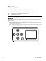
Other LCD Display Features
Status Bar
The Status Bar is present at all times and displays operational information for the luminaire. The Status Bar contains the
following information:
• CURVE – Displays dimmer curve type (linear curve/s-curve/square curve/PL curve)
•
ERRORS – Displays number of Errors or NO for zero errors.
•
MAP – Displays DMX map. For example, ‘16E’ for Enhanced or ‘16’ for standard. Other DMX map modes are 16-G1,
16-G3, 16-G12, 8-G1, 8-G3, 8-G12, et al.
•
ADDR – Displays the current DMX address for the fixture. NOTE: when the fixture does not detect a DMX input signal,
the DMX address text will display in red text.
VL 800 BeamLine
SQU
CURVE
NO
ERRORS
16G1
MAP
001
ADDR
ESC

88-105-7290-00 12
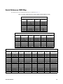
Quick Reference DMX Map
The summary list for the 16-Bit Mode DMX map is as indicated in Table 1-3.
Table 1-3: 16-Bit VL 800 BeamLine Luminaire DMX Channel Summary Listing
1 Group Mode (Default Mode)
DMX
Channel
Description
DMX
Channel
Description
1, 2 Pan 12 Intensity Timing
3, 4 Tilt 13 Color Timing
5 Pan Control 14 Focus Timing
6 Tilt Control 15 Control
7, 8 Intensity 16, 17 Red
9 Color Pre-Set 18, 19 Green
10 Strobe Rate 20, 21 Blue
11 Strobe Duration 22, 23 White
3 Group Mode
DMX
Channel
Description
DMX
Channel
Description
DMX
Channel
Description
1, 2 Pan 12 Intensity Timing 24, 25 Red (Group 2)
3, 4 Tilt 13 Color Timing 26, 27 Green (Group 2)
5 Pan Control 14 Focus Timing 28, 29 Blue (Group 2)
6 Tilt Control 15 Control 30, 31 White (Group 2)
7, 8 Intensity 16, 17 Red (Group 1) 32, 33 Red (Group 3)
9 Color Pre-Set 18, 19 Green (Group 1) 34, 35 Green (Group 3)
10 Strobe Rate 20, 21 Blue (Group 1) 36, 37 Blue (Group 3)
11 Strobe Duration 22, 23 White (Group 1) 38, 39 White (Group 3)
12 Group Mode
DMX
Channel
Description
DMX
Channel
Description
DMX
Channel
Description
DMX
Channel
Description
1, 2 Pan 22, 23 White (Group 1) 52, 53 Blue (Group 5) 82, 83 Green (Group 9)
3, 4 Tilt 24, 25 Red (Group 2) 54, 55 White (Group 5) 84, 85 Blue (Group 9)
5 Pan Control 26, 27 Green (Group 2) 56, 57 Red (Group 6) 86, 87 White (Group 9)
6 Tilt Control 28, 29 Blue (Group 2) 58, 59 Green (Group 6) 88, 89 Red (Group 10)
7, 8 Intensity 30, 31 White (Group 2) 60, 61 Blue (Group 6) 90, 91 Green (Group 10)
9 Color Pre-Set 32, 33 Red (Group 3) 62, 63 White (Group 6) 92, 93 Blue (Group 10)
10 Strobe Rate 34, 35 Green (Group 3) 64, 65 Red (Group 7) 94, 95 White (Group 10)
11 Strobe Duration 36, 37 Blue (Group 3) 66, 67 Green (Group 7) 96, 97 Red (Group 11)
12 Intensity Timing 38, 39 White (Group 3) 68, 69 Blue (Group 7) 98, 99 Green (Group 11)
13 Color Timing 40, 41 Red (Group 4) 70, 71 White (Group 7) 100, 101 Blue (Group 11)
14 Focus Timing 42, 43 Green (Group 4) 72, 73 Red (Group 8) 102, 103 White (Group 11)
15 Control 44., 45 Blue (Group 4) 74, 75 Green (Group 8) 104, 105 Red (Group 12)
16, 17 Red (Group 1) 46, 47 White (Group 4) 76, 77 Blue (Group 8) 106, 107 Green (Group 12)
18, 19 Green (Group 1) 48, 49 Red (Group 5) 78, 79 White (Group 8) 108.109 Blue (Group 12)
20, 21 Blue (Group 1) 50, 51 Green (Group 5) 80, 81 Red (Group 9) 110, 111 White (Group 12)

13 88-105-7290-00
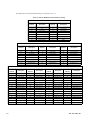
The summary list for the 8-Bit Mode DMX map is as indicated in Table 1-4.
Table 1-4: 8-Bit VL 800 DMX Channel Summary Listing
1 Group Mode
DMX
Channel
Description
DMX
Channel
Description
1, 2 Pan 11 Intensity Timing
3, 4 Tilt 12 Color Timing
5 Pan Control 13 Focus Timing
6 Tilt Control 14 Control
7 Master Intensity - High 15 Red
8 Color Pre-Sets 16 Green
9 Strobe Rate 17 Blue
10 Strobe Duration 18 White
3 Group Mode
DMX
Channel
Description
DMX
Channel
Description
DMX
Channel
Description
1, 2 Pan 11 Intensity Timing 19 Red (Group 2)
3, 4 Tilt 12 Color Timing 20 Green (Group 2)
5 Pan Control 13 Focus Timing 21 Blue (Group 2)
6 Tilt Control 14 Control 22 White (Group 2)
7 Master Intensity - High 15 Red (Group 1) 23 Red (Group 3)
8 Color Pre-Sets 16 Green (Group 1) 24 Green (Group 3)
9 Strobe Rate 17 Blue (Group 1) 25 Blue (Group 3)
10 Strobe Duration 18 White (Group 1) 26 White (Group 3)
12 Group Mode
DMX
Channel
Description
DMX
Channel
Description
DMX
Channel
Description
DMX
Channel
Description
1, 2 Pan 20 Green (Group 2) 37 Blue (Group 6) 54 White (Group 10)
3, 4 Tilt 21 Blue (Group 2) 38 White (Group 6) 55 Red (Group 11)
5 Pan Control 22 White (Group 2) 39 Red (Group 7) 51 Red (Group 10)
6 Tilt Control 23 Red (Group 3) 40 Green (Group 7) 52 Green (Group 10)
7
Master Intensity - High
24 Green (Group 3) 41 Blue (Group 7) 53 Blue (Group 10)
8 Color Pre-Sets 25 Blue (Group 3) 42 White (Group 7) 54 White (Group 10)
9 Strobe Rate 26 White (Group 3) 43 Red (Group 8) 55 Red (Group 11)
10 Strobe Duration 27 Red (Group 4) 44 Green (Group 8) 56 Green (Group 11)
11 Intensity Timing 28 Green (Group 4) 45 Blue (Group 8) 57 Blue (Group 11)
12 Color Timing 29 Blue (Group 4) 46 White (Group 8) 58 White (Group 11)
13 Focus Timing 30 White (Group 4) 47 Red (Group 9) 59 Red (Group 12)
14 Control 31 Red (Group 5) 48 Green (Group 9) 60 Green (Group 12)
15 Red (Group 1) 32 Green (Group 5) 49 Blue (Group 9) 61 Blue (Group 12)
16 Green (Group 1) 33 Blue (Group 5) 50 White (Group 9) 62 White (Group 12)
17 Blue (Group 1) 34 White (Group 5) 51 Red (Group 10)
18 White (Group 1) 35 Red (Group 6) 52 Green (Group 10)
19 Red (Group 2) 36 Green (Group 6) 53 Blue (Group 10)

88-105-7290-00 14
Notes

AMERICAS
10911 Petal Street
Dallas, TX 75235
Tel: +1 214-647-7880
Fax: +1 214-647-8039
ASIA
Unit C, 14/F, Roxy Industry Centre
41-49 Kwai Cheong Road
Kwai Chung, Kwai Tsing
Hong Kong
Tel: +852 2796 9786
Fax: +852 2798 6546
Room 1201, Freetown Tower D
E 3rd Ring Rd S, 58
Chaoyang Qu
Beijing Shi, China
Tel: +8610-58674776
Fax: +8610-58674775
B-1-27, Dataran Cascades, No. 13A
Jalan PJU 5/1
Kota Damansara PJU 5
47810 Petaling Jaya
Selangor, Malaysia
Tel: +60 3-7611 7302
Fax: +60 3-7629 4192
EUROPE
Rondweg Zuid 85
Winterswijk 7102 JD
Netherlands
Tel: +31 543-542516
Fax: +31 543-542513
24 Sovereign Park
Coronation Road
Park Royal, London
NW10 7QP
United Kingdom
Tel: +44 020 8965 3209
OCEANIA
14H Vega Place
Rosedale
Auckland 0632
New Zealand
Tel: +64 9-481-0100
VL800 BEAMLINE QUICK START GUIDE
DOCUMENT NUMBER:
88-105-7290-00
VERSION DATE: MAY 1 2019
© 2019 Signify Holding. All rights reserved.
All trademarks are owned by Signify Holding or their respective owners. The information pro-
vided herein is subject to change, without notice. Signify does not give any representation or
warranty as to the accuracy or completeness of the information included herein and shall not
be liable for any action in reliance thereon. The information presented in this document is not
intended as any commercial o er and does not form part of any quotation or contract, unless
otherwise agreed by Signify. Data subject to change.
-
 1
1
-
 2
2
-
 3
3
-
 4
4
-
 5
5
-
 6
6
-
 7
7
-
 8
8
-
 9
9
-
 10
10
-
 11
11
-
 12
12
-
 13
13
-
 14
14
-
 15
15
-
 16
16


Vari-Lite VL800 BEAMLINE Guide de démarrage rapide
- Taper
- Guide de démarrage rapide
dans d''autres langues
Documents connexes
-
Vari Lite VL 2600 Guide de démarrage rapide
-
Vari-Lite VL6000 BEAM Guide de démarrage rapide
-
-
-
-
-
-
-
-


