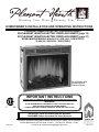
Pleasant Hearth 18-600-310 Homeowner's Installation And Operating Instructions Manual
- Catégorie
- Cheminées
- Taper
- Homeowner's Installation And Operating Instructions Manual
Ce manuel convient également à

Questions, problems, missing parts? Before returning to your retailer, call our customer
service department at 877-447-4768 8:30 a.m. – 4:30 pm CST, Monday – Friday.
or email us at [email protected]
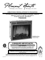
HOMEOWNER’S INSTALLATION AND OPERATING INSTRUCTIONS
20-10-089 Rev.0/10
For installation with
Pleasant Hearth
Fireplace Mantel
W a r m i n g Y o u r H o m e. W a r m i n g Y o u r H e a r t.
C US
INSTALLER: Leave this manual with the appliance.
CONSUMER: Retain this manual for future reference.
WARNING!
IF THE INFORMATION IN THIS MANUAL IS NOT FOLLOWED EXACTLY,
AN ELECTRICAL SHOCK OR FIRE MAY RESULT
CAUSING PROPERTY DAMAGE, PERSONAL INJURY OR LOSS OF LIFE.
IMPORTANT INSTRUCTIONS
PLEASE READ THIS MANUAL BEFORE INSTALLING AND USING APPLIANCE
PLEASANT HEARTH ELECTRIC FIREPLACE INSERT
FR-PLEASANT HEARTH ELECTRIC FIREPLACE INSERT (page 19)
SP-PLEASANT HEARTH ELECTRIC FIREPLACE INSERT (page 37)
MODEL/MODELE/MODELO #18-600-310 / GCE-1803 / GCE18TRG13 /
23-600-320 / GCE-2303 / GCE23TRG13
8280 Austin Avenue
Morton G r ov e, I L .
6 0 0 5 3 - 3 2 0 7
Tel: ( 847 ) 324 - 5900
Fax: ( 847 ) 324 - 5901
Toll Free (877) GHP Group
( 8 7 7 ) 4 4 7 - 4 7 6 8
www.ghpgroupinc.com
GHP

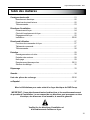
Safety Information ...................................................................................................3
Electrical Connection........................................................................................4
Grounding Instructions .................................................................................... 4
Remote Control................................................................................................ 5
Installation Instructions............................................................................................6
Fireplace Dimensions ........................................................................................ 6
Locating Your Fireplace ....................................................................................7
Fireplace Clearances ....................................................................................... 7
Installation.................................................................................................. 7 – 8
Operating Instructions.............................................................................................. 9
Fireplace Control Functions.............................................................................. 9
Control Panel.....................................................................................................9
Remote Control............................................................................................... 10
Care and Maintenance............................................................................................ 11
Glass Information............................................................................................11
Maintenance of Motors...................................................................................11
Cleaning................................................................................................11
Replacing the Light Bulbs ..................................................................... 12 - 13
Electrical Wiring Diagram .............................................................................. 14
Troubleshooting...................................................................................................... 15
Warranty..................................................................................................................................... 16
Replacement Parts List.................................................................................... 17 - 18
en Français .............................................................................................................. 19
en Español ...............................................................................................................37
Thank you and congratulations on your purchase of a GHP Group electric replace.
IMPORTANT: Read all instructions and warnings carefully before starting Installation.
Failure to follow these instructions may result in a possible electric shock,
injury to persons, re hazard and will void the warranty.
Please read the Installation & Operating Instructions
before using this appliance.
Electric Fireplace Insert 18/23
2
Table of Contents

Electric Fireplace Insert 18/23
3
SAVE THESE INSTRUCTIONS
1. Read all instructions before using this appliance.
2. This appliance is hot when in use. To avoid burns, do not let bare skin touch hot surfaces.
If provided, use handles when moving this appliance. Keep combustible materials, such as furniture,
pillows, bedding, papers, clothes and curtains at least 3 feet (914mm) from the front of this appliance.
3. CAUTION: Extreme caution is necessary when any heater is used by or near
children or invalids and whenever the heater is left operating unattended.
4. If possible always unplug this appliance when not in use.
5. Do not operate any heater with a damaged cord or plug or after the appliance
malfunctions, has been dropped or damaged in any manner.
6. Any repairs to this appliance should be carried out by a qualied service person.
7. Under no circumstances should this appliance be modied. Parts having to be removed
for servicing must be replaced prior to operating this appliance again.
8. Do not use outdoors.
9. This heater is not intended for use in bathrooms, laundry areas and similar indoor locations.
Never locate this appliance where it may fall into a bathtub or other water container.
10. Do not run cord under carpeting. Do not cover cord with throw rugs, runners or the like.
Arrange cord away from trafc areas and where it will not be tripped over.
11. To disconnect this appliance, turn controls to the off position, then remove plug from outlet.
12. Connect to properly grounded outlets only.
13. This appliance, when installed must be electrically grounded in accordance with local codes,
with the current CSA C22.1 Canadian Electrical codes or for USA installations,
follow local codes and the National Electric Code, ANSI/NFPA No. 70.
14. Do not insert or allow foreign objects to enter any ventilation or exhaust opening as this
may cause an electric shock, re or damage the appliance.
15. To prevent possible re, do not block air intakes or exhaust in any manner.
Do not use on soft surfaces, like a bed, where openings may become blocked.
16. This appliance has hot and arcing or sparking parts inside. Do not use it in areas where gasoline,
paint or ammable liquids are used or stored. This appliance should not be used as a
drying rack for clothing, nor should Christmas stockings or decorations be hung on or near it.
17. Use this appliance only as described in this manual. Any other use not recommended by the
manufacturer may cause re, electric shock or injury to persons.
18. Avoid the use of an extension cord because of the risk of overheating the cord and the risk of re.
Extension cords are for temporary use only. If an extension cord must be used,
it must be UL/CSA certied, rated at least for 15A (1875W), 125V with 14 AWG minimum and
constructed of two current carrying conductors with ground. A heavy duty extension
cord with the shortest length possible for the connection is recommended and must not be
longer than 50 ft. (15.2m). Do not coil or cover the extension cord.
Safety Information - IMPORTANT INSTRUCTIONS

A 15 amp, 120 Volt, 60 Hz circuit with a properly grounded outlet is required. Preferably, the replace will
be on a dedicated circuit as other appliances on the same circuit may cause the circuit breaker to trip
or the fuse to blow when the heater is in operation. The unit comes standard with a 6 ft. (1.8 m) long three
wire cord, exiting the right side of the replace. Plan the installation to avoid the use of an extension cord.
Extension cords are for temporary use only. If an extension cord must be used, it must be UL/CSA certied,
rated at 15A (1875W), 125V maximum with 14 AWG minimum and constructed of two current carrying conductors
with ground. A heavy duty extension cord with the shortest length possible for the connection is recommended
and must not be longer than 50 ft. (15.2 m). Do not coil or cover the extension cord.
Electrical outlet wiring must comply with local building codes and other
applicable regulations to reduce the risk of re, electrical shock
and injury to persons.
Do not use this replace if any part of it has been under water.
Immediately call a qualied service technician to inspect the replace
and replace any part of the electrical system which has been under water.
4
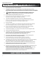
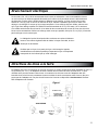
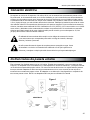
This heater is for use on 120 volts. The cord has a plug as shown at (A) in Figure 1. An adapter as shown at (C)
is available in the USA only for connecting three-blade grounding-type plugs to two-slot receptacles. The green
grounding lug extending from the adapter must be connected to a permanent ground such as a properly grounded outlet
box. The adapter should not be used if a three-slot grounded receptacle is available. NOTE: Adapters are NOT for
use in Canada.
Electrical Connection
Grounding Instructions
Electric Fireplace Insert 18/23
GROUNDING
PIN
METAL SCREW
GROUNDING
MEANS
COVER OF GROUNDED
OUTLET BOX
ADAPTER
(A)
(B)
(C)
(D)
Figure 1
GROUNDING
PIN

5
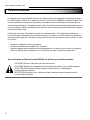
This equipment has been tested and found to comply with the limits for a Class B
digital device, pursuant to Part 15 of the FCC Rules and Industry Canada ICES-003.
These limits are designed to provide reasonable protection against harmful interference
in a residential installation. This equipment generates, uses, and can radiate radio
frequency energy and, if not installed and used in accordance with the instruction manual,
might cause harmful interference to radio communications.
However, there is no guarantee that interference will not occur in a particular installation.
If this equipment does cause harmful interference to radio or television reception, which can
be determined by turning the equipment off and on, the user is encouraged to try to correct the
interference by one or more of the following measures:
• Reorient or relocate the receiving antenna.
• Increase the separation between the equipment and receiver.
• Connect the equipment into an outlet on a circuit different from that to which the
receiver is connected.
• Consult the dealer or an experienced radio/TV technician for help.
DO NOT mix old and new batteries.
DO NOT use rechargeable Cadmium-sliver oxide cell batteries with remote control unit.
DO NOT mix Alkaline, Standard (Carbon-Zinc), or Rechargeable (Nickel-Cadmium) batteries.
DO NOT dispose of batteries in re. Improper disposal may cause batteries to leak or explode.
Remote Control
The remote control requires 1 Lithium Coin Cell Battery (size-CR2025) which is included.
Electric Fireplace Insert 18/23

6
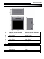
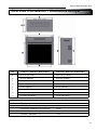
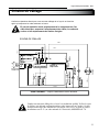
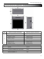
Installation Instructions - Fireplace Dimensions
Electric Fireplace Insert 18/23
Ref.
A 19-3/16" (487.5mm) 24-15/16" (617.5mm)
B 18-7/16" (469mm) 20-15/64" (514mm)
C 17-47/64" (450.5mm) 22-53/64" (580mm)
D 17-23/32" (450mm) 19-31/64" (495mm)
E 8-1/32" (204mm) 8-1/32" (204mm)
F 7-61/64" (202mm) 7-61/64" (202mm)
G 16-1/16" (408mm) 21-3/16" (538mm)
H 13-15/32" (342.5mm) 15-1/4" (387.5mm)
VOLTAGE 120 V AC
FREQUENCY 60Hz
HEATER RATING 1350W
MAX AMPS - 18" 12A
MAX AMPS - 23" 12.5A
Technical Specifications
18-600-310 / GCE-1803 / GCE18TRG13 23-600-320 / GCE-2303 / GCE23TRG13

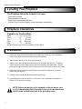
7
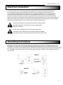
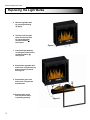
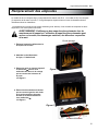
1. Locate your assembled Pleasant Hearth wood mantel near a 15 amp / 120 volt grounded
electric outlet. Read all instructions before using this appliance.
2. Place the insert directly in front of the mantel opening.
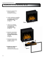
3. Carefully lift the insert through the center opening in the front of the replace. The bottom
of the insert has two foam rubber strips to prevent scratching of the hearth base. Slide the
insert back through the opening until the metal trim makes contact with the front of the mantel.
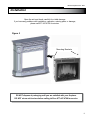
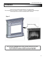
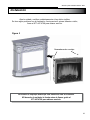
4. Install the mounting brackets provided with the insert in the pre-drilled holes on the top
of the insert (see Figure 2).
5. Carefully position mantel with installed replace against wall.
6. Plug the power cord into the 15 amp / 120 volt outlet. Use an extension cord rated for a
minimum of 1875 watts if necessary.
• Out of direct sunlight
• Not susceptible to moisture
• Away from uninsulated outside wall
• At least 3 feet (.9m) from drapery, furniture and other combustibles
The Fireplace should be located in an area:
NOTE: Make sure that the unit is installed so that the power cord
is not compressed against or caught on the unit or the mantel and
that it has an unobstructed path to the grounded outlet.
Locating Your Fireplace
Fireplace Clearances
Installation
Electric Fireplace Insert 18/23
Sides......................2
27
/
64
” (61.5 mm)
Floor.......................0” (0 mm)
Top.........................2” (51 mm)
Front......................36” (914 mm)
Rear.......................
25
/
32
” (20 mm)
Clearance to Combustibles
Wooden Facing (up to 5/8” (16 mm) thick): 5/16” (8mm)

8
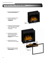
Open the unit and check carefully for visible damage.
If you have any problems with installation, operation, missing parts, or damage,
please call 877-447-4768 for service.
Figure 2
Mounting Brackets
DO NOT dispose of packaging until you are satised with your replace.
DO NOT return unit to store before calling toll free 877-447-4768 for service.
Installation
Electric Fireplace Insert 18/23

2
3
1
9
Electric Fireplace Insert 18/23
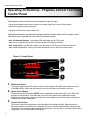
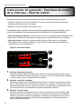
The replace features conveniently separate controls for ame effect and for heater control.
This allows you to operate the unit in two (2) different modes:
• As a full-featured replace - both ame effect and heater are on.This mode
allows you to enjoy the look of the re along with the heat output of a heater.
• As a visual effect - only the ame effect is on, the heater is off. We recommend this mode for
warm weather application, when you want the ambiance of a re, without any heat output.
The replace control functions can be accessed in two (2) ways:
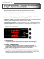
• Using the touchpad control panel, located in the upper right-hand corner of the replace
behind the hinged control access door.
• Using the multifunction remote control unit.
Main Power Button:
This button supplies power to all the functions of the replace. The Main power button must be
in the ON position, either from the remote or on the touch pad for the functions to work.
Heater Control Button:
This button controls the heater ON/OFF and 5 temperature modes from High to Low. When the
replace is rst turned on, the heater will come on at the highest room temperature setting.
Each time the Temperature button is pressed, the temperature set point decreases, allowing you
to adjust the ambient temperature.
Flame Control button:
This button controls the brightness of the ame effect with settings at High, Medium and Low.
When the replace is rst turned on, the ame will come on at the highest setting. Each time the
Flame button is pressed, the ame brightness decreases. The only way to turn off the ame effect
completely is to turn off the Main Power button.
1.
2.
3.
Operating Instructions - Fireplace Control Functions
Control Panel
Figure 3 / Control Panel

10
Electric Fireplace Insert 18/23
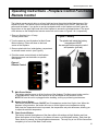
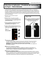
Figure 4
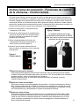
Remote Control
The infrared remote control relies on a line of sight and must be pointed at the ame/screen of the
replace to work. The remote control unit has the controls required to turn ON/OFF both the main
power and the heater. If you prefer to use the touchpad control on the replace unit itself, open the
hinged door on the upper right hand side of the replace to access the touchpad buttons. The layout
of the buttons on the touchpad and remote control unit can be seen in Figures 3 & 4, respectively.
1. Plug your replace into a 15 amp
120 volt power outlet.
2. Turn the power on (see illustration for Main Power
Button location). Flame will show on the back
screen of the replace.
3. Remove plastic tab from inside battery compartment
to activate remote control. (see Figure 5)
4. Point the remote control directly at the replace
ame/screen and use the buttons to operate
the replace.
Main Power Button:
This button supplies power to all the functions of the replace. The Main power button must be
in the ON position, either from the remote or on the touch pad for the functions to work.
NOTE: Be sure the unit is unplugged before installing, moving or performing maintenance.
Heater Control Button:
This button controls the heater ON/OFF and 5 temperature modes from High to Low. When the
replace is rst turned on, the heater will come on at the highest room temperature setting.
Each time the Temperature button is pressed, the temperature set point decreases, allowing you
to adjust the ambient temperature.
Flame Control Button:
This button controls the brightness of the ame effect with settings at High, Medium and Low.
When the replace is rst turned on, the ame will come on at the highest setting. Each time the
Flame button is pressed, the ame brightness decreases. The only way to turn off the ame effect
completely is to turn off the Main Power button.
1.
2.
Operating Instructions - Fireplace Control Functions
Remote Control
The plastic tab inside the battery
compartment MUST
be removed before remote control
will operate. (pull tab)
Figure 5 / Battery
3.
2
3
1

1. Under no circumstances should this product be operated with broken glass.
2. Do not strike or slam the glass.
3. Do not use abrasive cleaners to clean the glass.
4. This product uses tempered glass. Replacement of the glass supplied by the
manufacturer should be done by a qualied service person.
Always disconnect the appliance from the main power supply
and allow it to cool before any servicing operation.
The motors used on the fan heater and ame blower are pre-lubricated for extended bearing life
and require no further lubrication. However, periodic cleaning/vacuuming of the appliance around
the air intake and exhaust, as well as the fan heater is recommended. For heavy or continuous use,
periodic cleaning must be done more frequently. If the heater blows alternating cold and warm air,
check the fan for free movement and for debris restricting air ow. If the fan does not move freely, the
unit must be turned off and the fan replaced immediately in order to prevent further damage to the unit.
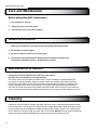
Before attempting ANY maintenance:
1. Turn off power to the unit.
2. Unplug the power cord from outlet.
3. Let replace cool if it has been operating.
11
Care and Maintenance
Glass Information
Maintenance of Motors
Cleaning
Cleaning of the control panel, located in the upper right-hand corner of the replace behind the hinged
control access door, is to be done only using a soft cloth, slightly dampened in water (if needed, a small
amount of dish soap can be added to the water) and dried using a clean, dry soft cloth. Cleaning of the
screen diffuser is to be done using only water and a lint free cloth. DO NOT use any abrasive household
cleaners as these products will damage the touchpad controls and the diffusing screen.
Electric Fireplace Insert 18/23

12
The 18” models use two (2) 40 watt, E-12 socket base light bulbs. The 23” models use two (2) 60 watt, E-12
socket base light bulbs. These are small base bulbs typically found in chadeliers with candle shaped bulbs.
The bulbs are located underneath the logset/ emberbed. For convenience, if one of the bulbs burns out, it may
be easier to replace both of the bulbs at the same time.
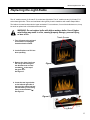
Replacing the Light Bulbs
Before attempting ANY maintenance:
1. Turn off power to the unit.
2. Unplug the power cord from outlet.
3. Let replace cool if it has been operating.
Electric Fireplace Insert 18/23
WARNING: Do not replace bulbs with higher wattage bulbs. Use of higher
rated bulbs may result in a re, causing property damage, personal injury,
or loss of life.
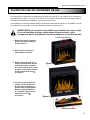
1. Turn off power to the unit and
ensure that it is unplugged
from the electrical outlet.
2. Let the replace cool if it has
been operating.
Thumb Screws
3. Remove the glass front from
the unit by unscrewing the
two thumbscrews counter-
clockwise at the top of
the glass door.
See Figure 5.
Figure 5
4. Locate the two log set bolts
on the left and right side of
the top of the ember bed and
remove them by unscrewing
them counterclockwise .
See Figure 6.
Figure 6
Log Bolts

13
Replacing the Light Bulbs
Electric Fireplace Insert 18/23
5. Remove log/ember bed
by grasping and lifting
up gently.
6. Visually locate the light
bulbs and remove them
by unscrewing them
counterclockwise .
See Figure 7.
7. Install new light bulbs by
screwing the bulbs into the
sockets clockwise .
See Figure 8.
8. Reinstall the log/ember bed
and secure using the two log
bolts previously removed.
See Figure 8.
Figure 7
9. Reinstall the glass front
and secure using the two
thumbscrews.
10. Restore power to the
unit and ensure that it
is operating properly.
Figure 8

14
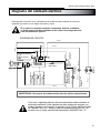
Any electrical repairs or rewiring of this unit should be carried out by a licensed electrician
in accordance with national and local codes.
If repairing or replacing any electrical component or wiring, the original
wire routing, color coding and securing locations must be followed.
Any electrical re-wiring of this appliance must be done by a qualied
electrician. This wiring must be done in accordance with local codes
and/or in Canada with the current CSA C22.1 Canadian Electrical Code,
and for US installations, the National Electrical Code ANSI/NFPA NO 70.
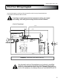
Electrical Wiring Diagram
WARNING: Disconnect Power Before Servicing
Electric Fireplace Insert 18/23
CIRCUIT DIAGRAM
4 Black
2 Black
1 Black
3 Black
8 White
11 White
10 White
9 White
7 White
5 Black
12 Black
Power I/O
Heater Circular
Control
Flame Circular
Control
Temperature
sensor
6 Black
Thermal
Cutout
of fuse
Fan Heater
Lamp
CIRCUIT
BOARD
Heater element
FUSE
Heating indicator
H L
Flame indicator
H/M/L

15
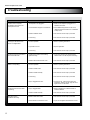
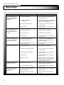
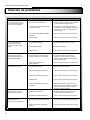
Troubleshooting
Corrective Action
Fireplace does not operate; 1. The fireplace is not plugged in. 1. Make sure the fireplace is plugged in to a
the ON/OFF power light on the standard 120V outlet.
control panel is not lit.
2. A circuit breaker is tripped or a fuse blown. 2. Check additional appliances on the circuit;
ideally the fireplace should be on a dedicated
15 amp circuit.
3. Defective ON/OFF switch. 3. Call customer service at (877) 447-4768.
4. Loose wiring. 4. Call customer service at (877) 447-4768.
Power light is ON but the back 1. Incorrect operation. 1. Refer to operating instructions.
flame is not bright/visible.
2. Light bulbs burnt out. 2. Replace light bulbs.
3. Loose wiring. 3. Call customer service at (877) 447-4768.
Excessive noise when the flame is 1. Rotating flame reflector shaft rubbing 1. Open back of firebox and reposition flame
ON but the heater OFF. against housing. reflector shaft. Turn off unit prior to servicing.
2. Defective flame reflector shaft motor. 2. Call customer service at (877) 447-4768.
Heater is not operating. 1. Incorrect operation. 1. Refer to operating instructions.
2. Defective heater switch. 2. Call customer service at (877) 447-4768.
3. Defective heater assembly. 3. Call customer service at (877) 447-4768.
4. Loose wiring. 4. Call customer service at (877) 447-4768.
5. Dirty or clogged louver door. 5. Unplug the unit. Clear louver area of dust
and debris. Wait five minutes, plug the unit in
again and turn on the heater.
Excessive noise when the heater 1. Dirty or clogged blower. 1. Refer to Maintenance of Motors section of
is operating. Instruction Manual.
2. Defective heater assembly. 2. Call customer service at (877) 447-4768.
Back flame light on 1. Defective flame effect motor. 1. Call customer service at (877) 447-4768.
but flames not moving.
2. Flame reflector not secured to motor. 2. Open unit and tighten flame reflector to motor.
Problem Possible Cause
Electric Fireplace Insert 18/23

16
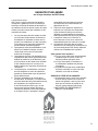
BASICWARRANTY:
GHP Group (hereinafter referred to collectively
as the “Company”) warrants that your new
electric replace is free from manufacturing and
material defects for a period of one year from
date of purchase, subject to the following
conditions and limitations.
1. This electric replace must be installed and
operated at all times in accordance with
the Installation and Operating instructions
furnished with the product. Any alteration,
willful abuse, accident, or misuse of the
product shall nullify this warranty.
2. This warranty is non-transferrable, and is
made to the original owner, provided that the
purchase was made through an authorized
supplier of the Company.
3. This warranty is limited to the repair or
replacement of part(s) found to be defective
in material or workmanship, provided that
such part(s) have been subjected to normal
conditions of use and service, after said defect
isconrmed by the Company’s inspection.
4. The Company may, at its discretion, fully
discharge all obligations with respect to this
warranty by refunding the wholesale price of
the defective part(s).
5. Any installation, labor, construction,
transportation, or other related costs/
expenses arising from defective part(s), repair,
replacement, or otherwise of same, will not
be covered by this warranty, nor shall the
Company assume responsibility for same.
Further, the Company will not be responsible
for any incidental, indirect, or consequential
damages, except as provided by law.
1 YEAR WARRANTY
For GHP Group Electric Fireplace
6. All other warranties - expressed or implied-
with respect to the product, its components
and accessories, or any obligations/liabilities
on the part of the Company are hereby
expressly excluded.
7. The Company neither assumes, nor
authorizes any third party to assume, on its
behalf, any other liabilities with respect to the
sale of this product.
8. The warranties as outlined within this
document do not apply to non-GHP Group
accessories used in conjunction with the
installation of this product.
This warranty is void if:
a) The replace has been operated in
atmospheres contaminated by chlorine,
uorine or other damaging chemicals.
b) The replace is subjected to prolonged
periods of dampness or condensation.
c) Any alteration, willful abuse, accident, or
misuse of the product.
IF WARRANTY SERVICE IS NEEDED . . .
1) Contact GHP Group customer service.
Make sure you have your warranty, your
sales receipt, and the model/serial number
of your GHP Group product.
2) DO NOT ATTEMPT TO DO ANY
SERVICE WORK YOURSELF.
Electric Fireplace Insert 18/23
8280 Austin Avenue
Mo r ton G r ove, I L.
6 0 0 5 3 - 3 2 0 7
Tel: ( 847 ) 324 - 5900
Fax: ( 847 ) 324 - 5901
Toll Free (877) GHP Group
( 8 7 7 ) 4 4 7 - 4 7 6 8
www.ghpgroupinc.com
GHP

17 20-10-089Printed in China
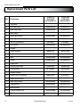
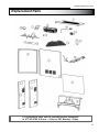
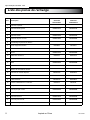
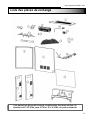
Replacement Parts List
Electric Fireplace Insert 18/23
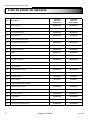
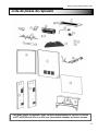
Ref. Description
18-600-310
GCE-1803
GCE18TRG13
23-600-320
GCE-2303
GCE23TRG13
1 Top panel
EF18023350X EF23022350X
2 Left side panel
EF18023351X EF23022351X
3 Right side panel
EF18023352X EF23022352X
4 Back panel
EF18023354X EF23022355X
5 Glass door frame
EF18023104X EF23022105X
6 Flame panel assembly
EF18023103X EF23022103X
7 Mounting bracket kit
EF33405A EF33405A
8 Fan-Heater
EF23022501X EF23022501X
9 Screen
EF18023366X EF23022389X
10 Flame reflector
EF18376A EF23373AS
11 Bulb base
EF23022505X EF23022505X
12 Bulb
EF18023505X EF23022504X
13 Logset
EF18023365X EF23022387X
14 Logset bolt
EF23022388X EF23022388X
15 Control panel label
EF18512AS EF18512AS
16 Control panel
EF33504AS EF33504AS
17 Remote control
EF33510AS EF33510AS
18 Power cord & connector
EF33511A EF33511A
19 Flame effect motor
EF23022506X EF23022506X
20 Main circuit board
EF23022502X EF23022502X
21 Glass panels
EF18023365X EF23022515X
22 Bottom panel
EF18023101X EF23022101X
23 Control access door
EF23022104X EF23022104X
24 Thumbscrew for glass door
EF23022394X EF23022394X

For replacement parts, call our customer service department
at 877-447-4768 8:30 a.m. – 4:30 p.m. CST, Monday – Friday.
18
Replacement Parts
Electric Fireplace Insert 18/23

Des questions, des problèmes, des pièces manquantes? Avant de retourner l’article au détaillant,
appelez notre service à la clientèle au 877 447 4768, entre 8 h 30 et 16 h 30, HNC, du lundi au
vendredi, ou envoyez-nous un courriel à l’adresse suivante : [email protected].
DIRECTIVES D’INSTALLATION ET D’UTILISATION
À installer avec le
manteau pour foyer
Pleasant Hearth.
C US
REMARQUE À L’INTENTION DE L’INSTALLATEUR : Veuillez laisser ce manuel au propriétaire.
REMARQUE À L’INTENTION DU CLIENT : Veuillez conserver ce manuel pour vous
y référer ultérieurement.
AVERTISSEMENT!
RESPECTEZ SCRUPULEUSEMENT LES DIRECTIVES DU PRÉSENT MANUEL
POUR PRÉVENIR LES CHOCS ÉLECTRIQUES, LES INCENDIES, LES
DOMMAGES AINSI QUE LES BLESSURES GRAVES OU MORTELLES.
CONSIGNES IMPORTANTES
VEUILLEZ LIRE CE MANUEL AVANT D’INSTALLER OU D’UTILISER LE FOYER.
FOYER ÉLECTRIQUE ENCASTRABLE PLEASANT HEARTH
MODÈLE Nº 18-600-310 / GCE-1803 / GCE18TRG13 /
23-600-320 / GCE-2303 / GCE23TRG13
FRANCÁIS
20-10-089 Rév. 0/10
Réchauffez votre résidence. Réchauffez votre cœur.
8280 Austin Avenue
Morton G r ov e, I L .
6 0 0 5 3 - 3 2 0 7
Tel: ( 847 ) 324 - 5900
Fax: ( 847 ) 324 - 5901
Toll Free (877) GHP Group
( 8 7 7 ) 4 4 7 - 4 7 6 8
www.ghpgroupinc.com
GHP

Merci et félicitations pour votre achat d’un foyer électrique de GHP Group.
IMPORTANT : Lisez attentivement toutes les directives et les avertissements avant
de procéder à l’installation. Le non-respect de ces directives peut provoquer un choc
électrique, des blessures et un incendie, et annule la garantie.
Veuillez lire les directives d’installation et
d’utilisation avant d’utiliser ce foyer.
20
Consignes de sécurité ........................................................................................... 21
Branchement électrique..................................................................................22
Directives de mise à la terre ............................................................................22
Télécommande ............................................................................................... 23
Directives d’installation..........................................................................................24
Dimensions du foyer .......................................................................................24
Choix de l’emplacement du foyer .................................................................... 25
Dégagement du foyer ..................................................................................... 25
Installation................................................................................................. 25-26
Directives d’utilisation .............................................................................................27
Fonctions de commande du foyer...................................................................27
Tableau de commande....................................................................................27
Télécommande............................................................................................... 28
Entretien................................................................................................................... 29
Renseignements sur la vitre............................................................................29
Entretien des moteurs.....................................................................................29
Nettoyage................................................................................................29
Remplacement des ampoules................................................................... 30-31
Schéma de câblage........................................................................................32
Dépannage............................................................................................................... 33
Garantie..................................................................................................................................... 34
Liste des pièces de rechange..........................................................................35-36
en Español ............................................................................................................... 37
Table des matières
Foyer électrique encastrable 18/23
La page est en cours de chargement...
La page est en cours de chargement...
La page est en cours de chargement...
La page est en cours de chargement...
La page est en cours de chargement...
La page est en cours de chargement...
La page est en cours de chargement...
La page est en cours de chargement...
La page est en cours de chargement...
La page est en cours de chargement...
La page est en cours de chargement...
La page est en cours de chargement...
La page est en cours de chargement...
La page est en cours de chargement...
La page est en cours de chargement...
La page est en cours de chargement...
La page est en cours de chargement...
La page est en cours de chargement...
La page est en cours de chargement...
La page est en cours de chargement...
La page est en cours de chargement...
La page est en cours de chargement...
La page est en cours de chargement...
La page est en cours de chargement...
La page est en cours de chargement...
La page est en cours de chargement...
La page est en cours de chargement...
La page est en cours de chargement...
La page est en cours de chargement...
La page est en cours de chargement...
La page est en cours de chargement...
La page est en cours de chargement...
La page est en cours de chargement...
La page est en cours de chargement...
-
 1
1
-
 2
2
-
 3
3
-
 4
4
-
 5
5
-
 6
6
-
 7
7
-
 8
8
-
 9
9
-
 10
10
-
 11
11
-
 12
12
-
 13
13
-
 14
14
-
 15
15
-
 16
16
-
 17
17
-
 18
18
-
 19
19
-
 20
20
-
 21
21
-
 22
22
-
 23
23
-
 24
24
-
 25
25
-
 26
26
-
 27
27
-
 28
28
-
 29
29
-
 30
30
-
 31
31
-
 32
32
-
 33
33
-
 34
34
-
 35
35
-
 36
36
-
 37
37
-
 38
38
-
 39
39
-
 40
40
-
 41
41
-
 42
42
-
 43
43
-
 44
44
-
 45
45
-
 46
46
-
 47
47
-
 48
48
-
 49
49
-
 50
50
-
 51
51
-
 52
52
-
 53
53
-
 54
54


Pleasant Hearth 18-600-310 Homeowner's Installation And Operating Instructions Manual
- Catégorie
- Cheminées
- Taper
- Homeowner's Installation And Operating Instructions Manual
- Ce manuel convient également à
dans d''autres langues
- English: Pleasant Hearth 18-600-310
- español: Pleasant Hearth 18-600-310
Documents connexes
-
Pleasant Hearth GLF-2404 Homeowner's Installation And Operating Instructions Manual
-
-
-
-
-
-
-
-
-
Autres documents
-
Muskoka MFB25WSC-1 Mode d'emploi
-
-
CFM HEF22 Manuel utilisateur
-
Pass and Seymour 1482ICC10 Mode d'emploi
-
Legrand Grounding Adaptor, 210G Instruction Sheet
-
-
Sharper Image LED Flameless Taper Candles (Set of 4) Le manuel du propriétaire
-
Classic Flame 80649 Manuel utilisateur
-
GCE VARIMED/S400 Mode d'emploi
-
Link2Home EM-TXC142B Mode d'emploi