Best ICB3I36SBN Guide d'installation
- Catégorie
- Hottes
- Taper
- Guide d'installation

ICB3I SERIES
HB0117
INSTALLATION INSTRUCTIONS
INTENDED FOR DOMESTIC COOKING ONLY
INSTALLER: LEAVE THIS MANUAL WITH HOMEOWNER.
HOMEOWNER: USE AND CARE INFORMATION ON PAGES 12 TO 14.
READ AND SAVE THESE INSTRUCTIONS
BEST; Hartford, Wisconsin www.BestRangeHoods.com 800-558-1711
BEST; Drummondville, QC, Canada www.BestRangeHoods.ca 866-737-7770
23866 rev. 03
! !

2
TO REDUCE THE RISK OF FIRE, ELECTRIC SHOCK OR
INJURY TO PERSONS, OBSERVE THE FOLLOWING:
1. Use this unit only in the manner intended by the manufacturer.
If you have questions, contact the manufacturer at the address
or telephone number listed in the warranty.
2. Before servicing or cleaning unit, switch power off at service
panel and lock service disconnecting means to prevent
power from being switched on accidentally. When the service
disconnecting means cannot be locked, securely fasten a
prominent warning device, such as a tag, to the service panel.
3. Installation work and electrical wiring must be done by
qualified personnel in accordance with all applicable codes
and standards, including fire-rated construction codes and
standards.
4. Sufficient air is needed for proper combustion and exhausting
of gases through the flue (chimney) of fuel burning equipment
to prevent backdrafting. Follow the heating equipment
manufacturer’s guidelines and safety standards such as
those published by the National Fire Protection Association
(NFPA) and the American Society for Heating, Refrigeration
and Air Conditioning Engineers (ASHRAE) and the local code
authorities.
5. When cutting or drilling into wall or ceiling, do not damage
electrical wiring and other hidden utilities.
6. Ducted fans must always be vented outdoors.
7. Do not use this unit with any additional solid-state speed
control device.
8. To reduce the risk of fire, use only metal ductwork.
9. This unit must be grounded.
10. All tempered glass can experience spontaneous breakage. If
broken, tempered glass falls out of its opening in interlocking
clumps. Tempered glass can, on occasion, break into large
shards rather than the classic tiny piece pattern.
11. When applicable, local regulations comprise more
restrictive installation and/or certification requirements,
the aforementioned requirements prevail on those of this
document and the installer agrees to conform to these at his
own expense.
TO REDUCE THE RISK OF A RANGE TOP GREASE FIRE:
a) Never leave surface units unattended at high settings. Boilovers
cause smoking and greasy spillovers that may ignite. Heat oils
slowly on low or medium settings.
b) Always turn hood ON when cooking at high heat or when
flambeing food (i.e.: Crêpes Suzette, Cherries Jubilee,
Peppercorn Beef Flambé).
c) Clean ventilating fans frequently. Grease should not be allowed
to accumulate on fan, filters or in exhaust ducts.
d) Use proper pan size. Always use cookware appropriate for the
size of the surface element.
1. For indoor use only.
2. For general ventilating use only. Do not use to exhaust
hazardous or explosive materials and vapors.
3. To avoid motor bearing damage and noisy and/or unbalanced
impellers, keep drywall spray, construction dust, etc. off power
unit.
4. Your hood motor has a thermal overload which will automatically
shut off the motor if it overheats. The motor will restart when it
cools down. If the motor continues to shut off and restart, have
the hood serviced.
5. The hood distance above cooktop must not be less than 30”.
A maximum of 36” above cooktop is highly recommended for
best capture of cooking impurities.
6. Two installers are recommended because of the large size and
weight of this unit.
7. To reduce the risk of fire and to properly exhaust air, be sure to
duct air outside — Do not exhaust air into spaces within walls
or ceiling or into attics, crawl space or garage.
8. Because of the high exhausting capacity of this unit, you
should make sure enough air is entering the house. Open a
window close to or in the kitchen.
9. To reduce the risk of fire and electrical shock, the Best ICB3I
Series models should only be installed with their own built-in
blower.
10. Please read specification label on product for further
information and requirements.
11. This hood is equipped with an RF receiver. See next page for
related warning.
WARNING
!
CAUTION
TO REDUCE THE RISK OF INJURY TO PERSONS IN THE
EVENT OF A RANGE TOP GREASE FIRE, OBSERVE
THE FOLLOWING*:
1. SMOTHER FLAMES with a close-fitting lid, cookie sheet or
metal tray, then turn off the burner. BE CAREFUL TO PREVENT
BURNS. IF THE FLAMES DO NOT GO OUT IMMEDIATELY,
EVACUATE AND CALL THE FIRE DEPARTMENT.
2. NEVER PICK UP A FLAMING PAN — You may be burned.
3. DO NOT USE WATER, including wet dishcloths or towels —
This could cause a violent steam explosion.
4. Use an extinguisher ONLY if:
A. You own a Class ABC extinguisher and you know how to
operate it.
B. The fire is small and contained in the area where it started.
C. The fire department has been called.
D. You can fight the fire with your back to an exit.
* Based on “Kitchen Fire Safety Tips” published by NFPA.
WARNING
!

3
WARNING
!
This hood is equipped with a RF receiver (optional remote control sold separately). Changes or modifications
not expressly approved by the party responsible for compliance could void the user’s authority to operate this
product. The remote control has been tested and found to comply with the limits for a Class B digital device,
pursuant to part 15 of the FCC Rules and the Canadian ICES-003. These limits are designed to provide reasonable
protection against harmful interference in a residential installation. The remote control generates, uses and can
radiate radio frequency energy and, if not installed and used in accordance with the instructions, may cause
harmful interference to radio communications. However, there is no guarantee that interference will not occur in
a particular installation. If this equipment does cause harmful interference to radio or television reception, which
can be determined by turning the equipment off and on, the user is encouraged to try to correct the interference
by one or more of the following measures:
• Reorient or relocate the receiving antenna
• Increase the separation between the equipment and receiver
• Connect the equipment into an outlet on a circuit different from that to which the receiver is connected
TABLE OF CONTENTS
1. I NSTALL DUCTWORK ................................................................................................................................................................................... 3
2. P
REPARE INSTALLATION ............................................................................................................................................................................... 4
3. M
EASURE INSTALLATION .............................................................................................................................................................................. 4
4. INSTALL MOUNTING BRACKET ........................................................................................................................................................................ 5
5. ASSEMBLE ANGLE BRACKETS ........................................................................................................................................................................ 6
6. REMOVE HYBRID FILTERS ............................................................................................................................................................................. 7
7. I NSTALL GLASS PANELS (SBN MODEL ONLY) ...................................................................................................................................................... 7
8. PREPARE HOOD (ALL MODELS) .................................................................................................................................................................. 8-9
9. INSTALL HOOD ...................................................................................................................................................................................... 9-10
10. CONNECT WIRING .....................................................................................................................................................................................11
11. REINSTALL HYBRID FILTERS .........................................................................................................................................................................11
12. LED LIGHTING .........................................................................................................................................................................................12
13. CARE .....................................................................................................................................................................................................12
14. OPERATION ........................................................................................................................................................................................ 13-14
15. WIRING DIAGRAM ......................................................................................................................................................................................14
16. SERVICE PA RTS ........................................................................................................................................................................................15
17. WARRANTY .............................................................................................................................................................................................16
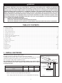
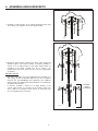
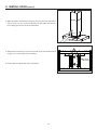
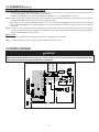
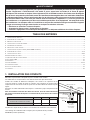
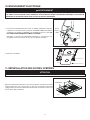
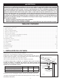
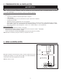
1. INSTALL DUCTWORK
Plan where and how the ductwork will be installed.
A straight, short duct run will allow the hood to perform most efficiently.
Install proper-sized ductwork, elbows and roof cap. Connect metal ductwork to cap and
work back towards the hood location. Use 2” metal foil duct tape to seal the joints.
Run 3-wire power supply cable to installation location.
We recommend to install the hood at a minimum distance of 30” above cooking
surface. A maximum of 36” above cooktop is highly recommended for best capture
of cooking impurities.
8” ROUND DUCT
ROOF CAP
HOOD
HH0152A
DECORATIVE
FLUE
8” ROUND
ADAPTER
/DAMPER
30” TO 36” ABOVE
COOKING SURFACE
CEILING HEIGHT 8 FEET 9 FEET 10 FEET*
M
INIMUM DISTANCE RECOMMENDED ABOVE
COOKTOP
30 IN. 30 IN. 30 IN.
M
AXIMUM RECOMMENDED HEIGHT 34 IN. 36 IN. 36 IN.
* 10-ft. ceilings require 10-ft flue extension, part no. AEICB3SB (sold separately).
Distances over 36” are at the installer and users discretion.

4
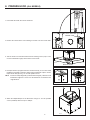
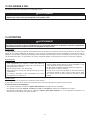
2. PREPARE INSTALLATION
WARNING
VQ0010
!
When performing installation, servicing or cleaning the unit, it is recommended to wear safety glasses and gloves.
NOTE: Before proceeding to the installation, check the contents of the box. If items are missing or damaged, contact the manufacturer.
Make sure that the following items are included:
– Hood
– Accessories
• Decorative flue assembly (lower and upper flues)
• 2 Hybrid filters
• 1 Ceiling mounting bracket (screwed on top of the hood)
• 8 Angle brackets
• 8” Round adapter/damper (in a separate box)
• Bag of parts (taped on the blower box) including: 2 wire connectors, 1 wire clamp, 8 no. 10 x 1 1/2” wood screws,
8 steel washers, 10 no. 8 x 3/8” quadrex screws, 17 no. 10-32 flanged locknuts, 50 x 10-32 x 1/2 quadrex hex head screws,
2 no. 8-1/2 low profile Phillips screws.
Parts sold separately:
– Ducts, elbows, wall and roof caps.
– Optional flue extension for 10-ft. ceilings model no. AEICB3SB.
– Optional remote control (model no. ACR3).
– Glass panels for ICB3I36SBN model (see replacement parts list).
NOTE: During installation, protect countertop and/or cooktop.
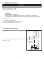
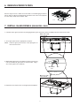
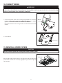
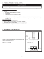
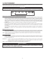
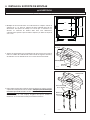
3. MEASURE INSTALLATION
HH0157A
C
B
A
CEILING
COOKTOP
BLOWER
BOX
TOP
12
3
⁄16"
C = B - A - 12
3
⁄16"
RANGE
HOOD
BOTTOM
Determine the required distance between the ceiling and the top of the blower
box (C) based upon ceiling height (B) and desired height of hood above cooktop (A).
NOTE: C = B - A - 12 3/16”

5
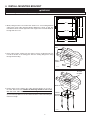
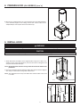
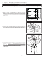
4. INSTALL MOUNTING BRACKET
WARNING
VQ0010
!
When building framework, always follow all applicable construction codes and standards.
10¼"
10¼"
9
3
⁄8"
9
3
⁄8"10
3
⁄8"
10
3
⁄8"
HK0062A
MAX. 9¾"
1. Modify ceiling structure over hood location. Install 2" x 4" cross framing between
ceiling joists using ceiling mounting bracket dimensions shown at right. The
framework must be sized to support the total weight of the hood and should not
be larger than 9¾" x 9¾".
2. Finish ceiling surface, making sure the ceiling is level in all direction. Be sure
to mark the location of the ceiling joists and cross framing. Bring house wiring
through finished ceiling.
C
EILING
JOISTS
HD0432
CROSS
FRAMING
HOUSE
WIRING
3. Remove both screws retaining the ceiling mounting bracket to the top of
the hood. Discard screws. Position the mounting bracket in such a way
that one of the sides without a “T” will be facing the front of the hood.
Secure mounting bracket to the ceiling using 8 no. 10 x 1½" wood screws
(2 on each corner). Make sure screws are driven into the center of the framing for
maximum strength.
HD0442
8” ROUND
DUCTWORK
FRONT OF HOOD
CEILING
MOUNTING
BRACKET

6
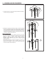
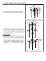
5. ASSEMBLE ANGLE BRACKETS
HD0421
1. Assemble 4 angle brackets to the ceiling mounting bracket using
16 no.10-32 x 1/2" quadrex screws (4 per angle bracket).
2. Determine angle brackets length based upon ceiling height and
desired height of hood above cooktop. If required, assemble a
second set of 4 angle brackets to the upper angle bracket set
according to the length needed. Use 16 no. 10-32 x 1/2"
quadrex screws and 16 no. 10-32 lock nuts (4 at each angle bracket
connection).
FOR 10-FT. CEILINGS
Both lower and upper flues are included with the hood, but for a
10-ft. ceiling, discard the provided upper flue and use the optional
extension flue, part AEICB3SB (sold separately). Four additional
angle brackets and additional mounting hardware are included with
the optional flue extension.
If need be, assemble a third set of 4 angle brackets to the
second angle bracket set according to the length needed. Use
16 no. 10-32 x 1/2" quadrex screws and 16 no. 10-32 lock nuts
(4 at each angle bracket connection).
HD0422
FOR 10-FT.
CEILINGS
(IF REQUIRED)

7
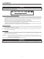
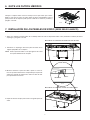
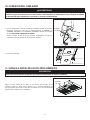
6. REMOVE HYBRID FILTERS
HO0349
Rest the range hood on a table. Protect the table to avoid damaging it. Remove
tape on filters. Lift filters by pushing them towards the back of the hood (opposite
to control side) and flip, then set filters aside.
7. INSTALL GLASS PANELS (SBN MODEL ONLY)
The SBN hood model decorative glass panels are sold separately and have to be installed before completing the hood installation.
HD0568
HD0569
FRONT GLASS PANEL
STUDS LOCATION
REAR GLASS PANEL
STUDS LOCATION
HD0558
GLASS PANEL
STUD
NUT
1. Carefully remove glass panel from its packaging. Remove glass panel nuts (factory installed) from both studs and set aside.
2. Insert glass panel studs in appropriate hood holes.
NOTE: Install the glass panel with the control pictograms on
the front of the hood.
3. While holding glass panel, pre-tighten the previously removed
nuts by hand. Ensure glass panel is centered. Then, using a
3/8” socket, tighten nuts completely.
4. Repeat the same steps for the second glass panel installation.

8
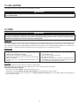
8. PREPARE HOOD (ALL MODELS)
1. From inside the hood, disconnect the blower.
HE0063
HE0062
ELECTRICAL COMPARTMENT
RETAINING SCREW
2. Remove the electrical box cover retaining screw. Set cover and screw aside.
HD0425
SCREW LOCATIONS
3. Turn the hood over and remove blower box 8 retaining screws (only 4 out of
8 screws illustrated at right). Set hood and screws aside.
HO0188
1
2
4. Lift flap located on top right hand corner of blower box (1) to ease wire clamp
installation (included). Install wire clamp and push flap back in place. Secure
flap to blower box (2) using 1 no. 8 x 3/8" quadrex screw.
NOTE: Install wire clamp diagonally (as illustrated in image 2), otherwise it will
be difficult to tighten its screws once the blower box is attached to the
angle brackets.
HJ0066
5. Attach the adapter/damper to the blower box using 4 no. 8 x 3/8" quadrex
screws (included). Remove tape on damper.

9
8. PREPARE HOOD (ALL MODELS) (CONT’D)
HJ0067
6. Measure the required length of 8" round metal duct from the adapter/damper
to the ductwork rough-in in the ceiling. Connect this section of duct to the
adapter/damper and seal joint with metal foil duct tape.
9. INSTALL HOOD
WARNING
!
BE CAREFUL when installing the decorative flue and hood, they may have sharp edges.
CAUTION
DO NOT REMOVE the protective plastic film covering the decorative flue (upper and lower) and the hood yet.
HD0424
FRONT
HOUSE WIRING
1. Attach blower box assembly to lower angle brackets using 16 no. 10-32 x 1/2"
quadrex screws (4 per angle brackets). Connect hood duct to ceiling duct and
seal joint with metal foil duct tape.
NOTE: Ensure electrical channel is facing where the front of the hood will be
positioned.
2. Run house wiring through wire clamp into blower box electrical channel. Tighten
wire clamp to secure house wiring cable to blower box.
NOTE: The length between the top of the blower box and the bottom of the hood
is 12 3⁄16".
HD0565
12
SEAM

10
HD0426
SCREW LOCATIONS
4. Attach the hood to the blower box using the 8 screws previously removed at
step 8.3 (only 4 out of 8 screws are illustrated at right). Make sure that the
house wiring goes into the electrical compartment.
9. INSTALL HOOD (CONT’D)
HD0559
SCREW LOCATIONS
ELECTRICAL
COMPARTMENT
5. Slide the lower flue down on top of the hood and secure from inside the hood
using 4 no. 8 x 3/8" quadrex screws (included).
6. Remove protective plastic film from hood and flues.

11
10. CONNECT WIRING
WARNING
!
Risk of electric shock. Electrical wiring must be done by qualified personnel in accordance with all applicable
codes and standards. Before connecting wires, switch power off at service panel and lock service disconnecting
means to prevent power to be switched on accidentally.
HE0061
GROUND
SCREW
1. Connect hood power cable to house wiring using provided wire connectors:
BLACK to BLACK, WHITE to WHITE and GREEN or BARE wire to GREEN
ground screw. DO NOT FORGET TO CONNECT THE GROUND.
Reinstall electrical box cover ensuring its 3 tabs are tucked inside the electrical
channel.
2. Connect blower.
HE0060
CONNECT
BLOWER
11. REINSTALL HYBRID FILTERS
CAUTION
Remove protective plastic film covering filters before reinstalling them.
HO0350
FILTER TABS
Rest rear filters edge on filter springs in the range hood. Tilt up the filters into
position. Make sure filter tabs are securely engaged in range hood front edge slots
after installation.

12
12. LED LIGHTING
The lighting of this hood is produced by two LED modules (included).
WARNING
!
Do not touch lamps during or soon after operation. Burns may occur. Cannot be replaced by any other type of light
bulb or LED module.
13. CARE
WARNING
!
Before servicing or cleaning the unit, switch power off at service panel and lock service panel to prevent power
from being switched on accidentally. When the service disconnecting means cannot be locked, securely fasten a
prominent warning device, such as a tag, to the service panel.
HYBRID FILTERS
Hybrid filters should be cleaned monthly. Remove hybrid filters by pushing them towards the back of the hood and rotating them downward.
Use a warm detergent solution to clean the filters. Let them dry and reinstall them. Hybrid filters are dishwasher safe. Clean all-metal filters
in the dishwasher using a non-phosphate detergent. Discoloration of the filter may occur if using phosphate detergent or as a result of local
water conditions — but this will not affect filter performance. This discoloration is not covered by the warranty.
STAINLESS STEEL
Do:
• Regularly wash with clean cloth or rag soaked with warm water
and mild soap or liquid dish detergent.
• Always clean in the direction of original polish lines.
• Always rinse well with clear water (2 or 3 times) after cleaning.
Wipe dry completely.
• You may also use a specialized household stainless steel
cleaner.
Don’t:
• Use any steel or stainless steel wool or any other scrapers to
remove stubborn dirt.
• Use any harsh or abrasive cleansers.
• Allow dirt to accumulate.
• Let plaster dust or any other construction residues reach the
hood. During construction/renovation, cover the hood to make
sure no dust sticks to stainless steel surfaces.
GLASS PANEL
Hot water with mild soap or glass cleaner is all that is usually needed.
When using mild soap, rinse with clear water. Wipe dry with a clean, soft cloth to avoid water marks.
Avoid when choosing a detergent:
- Any cleaners that contain bleach. They will attack stainless steel.
- Any products containing chloride, fluoride, iodide, bromide. They will deteriorate surfaces rapidly.
- Any combustible products used for cleaning such as acetone, alcohol, ether, benzol, etc. They are highly explosive and should never
be used close to a range.

13
14. OPERATION
Always turn your hood on before you begin cooking to establish an air flow in the kitchen. Let the blower run for a few minutes to clear the
air after you turn off the range.
CAUTION
After a power failure or during the range hood power up, a 5-second booting sequence is executed. Wait for the
control backlighting to turn off before use.
HC0052
A
B
CD
A. DELAY BUTTON/CONTROL LOCK (DOUBLE FUNCTION BUTTON):
i. When a blower speed is selected, press this button to activate the delay function. The delay button will light to its high intensity, then
to its mid intensity to indicate this function is activated; the selected blower speed button will alternate every 2 seconds between its
high intensity and its mid intensity. The blower will continue to operate for 5 minutes and will stop automatically. Selecting another
speed while the delay function is activated will not deactivate the function or reset the timer. To cancel the delay function, press the
delay button once again, or press the selected speed button which will also turn the blower off.
ii. When the blower is off, it is possible to lock the control interface in order to clean the glass panel.
To lock the control interface: Press and hold this button for 2 seconds. The button will light to its high intensity and flash three times,
it will then stay on its mid intensity to indicate that the control interface is locked.
To unlock the control interface: Press and hold this button for 2 seconds. The button will light to its high intensity and flash 3 times,
it will then fade out to its low intensity to indicate that the control interface is unlocked.
B. SPEED SELECTION BUTTONS:
Press the button corresponding to the desired blower speed (from 1 for low speed to 4 for high speed). The chosen speed button will
light to its high intensity then fade to its mid intensity. To turn off the blower, press once more on the corresponding blower speed
button; the button light will fade to its low intensity.
NOTE: When blower is off, pressing on blower speed 1 button will cause the blower to start on second speed for a very short lapse of
time, and then resume to speed 1.
C. MASTER ON/OFF:
When the blower and lights are off, press this button to turn the hood on to the last memorized speed level and light intensity. If there
are no memorized speed level and light intensity, speed will be set at level 1 and light intensity at 3. To turn off the blower and the
light simultaneously, press this button once.
HEAT SENTRY™: The hood is equipped with a HEAT SENTRY thermostat. If blower is ON at a lower speed setting and excessive heat is
detected above the cooking surface, it turns the blower up to third speed. When the temperature level drops to normal,
the blower will return to its original setting.
NOTE: When Heat Sentry is activated, the “DELAY OFF” function is inactivated.
WARNING
!
The Heat Sentry can change the blower speed when excessive heat is detected above the cooking surface. If this
situation occurs and you must stop the blower, press on the third speed button or on the master ON/OFF button.

14
REMOTE CONTROL:
This hood can also be operated using the optional ACR3 remote control (purchase separately).
NOTE: For more information, refer to the instructions included with the remote control.
14. OPERATION (CONT’D)
D. LIGHT BUTTON/BACKLIGHTING COLOR (DOUBLE FUNCTION BUTTON):
i. This button allows three different lighting levels according to your needs. Press once for full intensity, twice for intensity level 2, and
once more for nightlight. To turn off the lights, press once more.
If desired, when the lights are on, press and maintain the light button for 1 second; lights will be turned off.
NOTE: When only the lights are ON to any intensity and no interaction with the hood is detected for a 10-second period, the 7 buttons
backlighting will fade to its low intensity, acting as a night light feature.
ii. When lights are off, pressing and holding this button for 1 second will switch the backlighting color from white to blue or from blue
to white (default backlighting color is white) and memorize it. The button will flash three times to indicate that the color change has
been made.
NOTE: Due to the particular sensitivity of the control interface, keep the glass panel clean as dirt and condensation may cause erratic
operation of the hood blower and/or lighting. If this situation occurs, wipe the glass panel and wait 90 seconds. Then, adjust the
blower and/or lighting at your convenience.
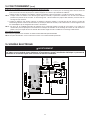
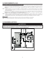
15. WIRING DIAGRAM
WARNING
!
Risk of electric shock. Electrical wiring must be done by qualified personnel in accordance with all applicable
codes and standards. Before connecting wires, switch power off at service panel and lock service disconnecting
means to prevent power from being switched on accidentally.
Line
Neutral
Ground
120 V AC
16 Pins
LED driver
Input
Output
LED
LED
User Interface
T1 (10 VAC)
FAN MOTOR
1
3
2
5
4
User Interface
J1
10VAC
J8
Aux. Input
3
2
1
RP1
J3
Programmer
header
Triac Ext
J7
J11
12VDC
+
-
J4
Motor Speed
J2
120V-
Motor-Lamp
1
RF communication
J10
J9
Serial Com
5
4
32
1
J5
Output
J6
External
Triac
2
3
4
5
1
2
3
4
1
2
1
2
1
2
3
4
1
2
3
1
2
YEL
BLK
BLK
WHT
WHT
WHT
RED
RED
RED
BLU
WHT
ORG
BLK
WHT
BLK
WHT
RED
RED
WHT
BLK
WHT
RED
GRY
BRN
BLU
WHT
ORG
BLK
BLK BLACK
BLU BLUE
BRN BROWN
GRN GREEN
GRY GREY
ORG ORANGE
RED RED
WHT WHITE
YEL YELLOW
COLOR CODE
HE0057A

15
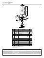
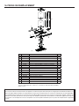
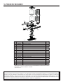
16. SERVICE PARTS
HL0449
1
2
3
4
5
6
7
8
9
10
11
12
13
14
15
KEY
NO.
P
ART NO.DESCRIPTION QTY.
1 SV09956XX* F
RONT GLASS PANEL 1
2 SV22427 ELECTRONIC CONTROL 1
3 SV21221 POWER UNIT 1
4 SV20816 PCB FOR REMOTE CONTROL 1
5 SV09022 TRANSFORMER 1
6 SV08582 I
NTERNAL BLOWER 1
7 62248 LED DRIVER AND CONNECTION HARNESS 1
8 62612 LED MODULE (1) 2
9 SV62053 HYBRID FILTER 15.875” X 14” x 0.5” (1) 2
10 SV09957XX* BACK GLASS PANEL 1
11 SV08543 8” ROUND ADAPTER/DAMPER 1
12 SV09518 ANGLE BRACKET KIT (4) 2
13 SV19232 INSTALLATION BRACKET 1
14 SV19231 U
PPER FLUE COVER 1
15 SV19230 LOWER FLUE COVER 1
** SV23894 CRT KIT 300 CFM (OPTIONAL)1
** SV23866 INSTALLATION MANUAL 1
** SV09871 PARTS BAG 1
** SV05869 BEST LOGO 1
*P
ART NUMBER ACCORDING TO GLASS PANEL COLOR, PLEASE CONTACT
CUSTOMER SERVICE OR REFER TO WEB SITE.
**ITEM NOT SHOWN.
R
EPLACEMENT PARTS AND REPAIRS
In order to ensure your unit remains in good working condition, you must use Broan-NuTone genuine replacement parts only. Broan-
NuTone genuine replacement parts are specially designed for each unit and are manufactured to comply with all the applicable
certification standards and maintain a high standard of safety. Any third party replacement part used may cause serious damage and
drastically reduce the performance level of your unit, which will result in premature failing. Broan-NuTone recommends to contact a
certified service depot for all replacement parts and repairs.

16
17. WARRANTY
FIVE-YEAR LIMITED WARRANTY FOR BEST
®
PRODUCTS
Warranty Period and Exclusions: Broan-NuTone, LLC (the “Company”) warrants to the consumer purchaser of its product (“you”) that the product (the
“Product”) will be free from material defects in the materials or its workmanship for a period of five (5) years from the date of original purchase (or such
longer period as may be required by applicable law) or a period of two (2) years from the date of service for any labor provided on the Product.
The limited warranty period for any replacement parts provided by the Company and for any Products repaired or replaced under this limited warranty shall
be the remainder of the original warranty period (or such longer period as may be required by applicable law).
THIS WARRANTY DOES NOT EXTEND TO FLUORESCENT LAMP STARTERS, TUBES AND BULBS, FUSES, FILTERS, DUCTS, ROOF CAPS, WALL CAPS
AND OTHER ACCESSORIES FOR DUCTING. This warranty does not cover (a) normal maintenance and service, (b) normal wear and tear, (c) any Products or
parts which have been subject to misuse, abuse, abnormal usage, negligence, accident, improper or insufficient maintenance, storage or repair (other than
repair by the Company), (d) damage caused by faulty installation, or installation or use contrary to recommendations or instructions, (f) damage caused by
exposure to salt air, (g) damage in transit, (h) natural wear of finish, (i) Products in commercial or nonresidential use, (j) damage caused by fire, flood or
other act of God, or (k) Products with altered, defaced or removed serial numbers. This warranty covers only Products sold to consumers in North America.
This warranty supersedes all prior warranties and, subject to applicable law, is not transferable from the original consumer purchaser.
No Other Warranties: This Limited Warranty contains the Company’s sole obligation and your sole remedy for defective Products. The foregoing warranties
are exclusive and in lieu of any other warranties and conditions, express or implied. TO THE MAXIMUM EXTENT PERMITTED BY APPLICABLE LAW, THE
COMPANY DISCLAIMS AND EXCLUDES ALL OTHER EXPRESS WARRANTIES AND CONDITIONS, AND DISCLAIMS AND EXCLUDES ALL WARRANTIES
AND CONDITIONS IMPLIED BY LAW, INCLUDING WITHOUT LIMITATION THOSE OF MERCHANTABILITY AND FITNESS FOR A PARTICULAR PURPOSE.
To the extent that applicable law prohibits the exclusion of implied warranties or conditions, the duration of any applicable implied warranty or condition
is limited to the period specified for the express warranty above. Some jurisdictions (which may include the Province of Quebec or specific US states) do
not allow limitations on how long an implied warranty lasts, so the above limitation may not apply to you. Any oral or written description of the Product is
for the sole purpose of identifying it and shall not be construed as an express warranty.
Whenever possible, each provision of this Limited Warranty shall be interpreted in such manner as to be effective and valid under applicable law, but if any
provision is held to be prohibited or invalid, such provision shall be ineffective only to the extent of such prohibition or invalidity, without invalidating the
remainder of such provision or the other remaining provisions of the Limited Warranty.
Remedy: During the applicable limited warranty period, the Company will, at its option, provide replacement parts for, or repair or replace, without charge,
any Product or part thereof, to the extent the Company finds it to be covered by and in breach of this limited warranty under normal use and service. The
Company will ship the repaired or replaced Product or replacement parts to you at no charge. You are responsible for all costs for removal, reinstallation
and shipping, insurance or other freight charges incurred in the shipment of the Product or part to the Company. If you must send the Product or part
to the Company, as instructed by the Company, you must properly pack the Product or part—the Company is not responsible for damage in transit. The
Company reserves the right to utilize reconditioned, refurbished, repaired or remanufactured Products or parts in the warranty repair or replacement
process. Such Products and parts will be comparable in function and performance to an original Product or part and warranted for the remainder of the
original warranty period (or such longer period as may be required by applicable law).
Company reserves the right, in its sole discretion, to refund the money actually paid by you for the Product. If the Product or component is no longer
available, replacement may be made with a similar product of equal or greater value, at Company’s sole discretion. This is your sole and exclusive remedy
for breach of this limited warranty.
Exclusion of Damages: THE COMPANY’S OBLIGATION TO PROVIDE REPLACEMENT PARTS, OR REPAIR OR REPLACE, AT THE COMPANY’S OPTION,
SHALL BE YOUR SOLE AND EXCLUSIVE REMEDY UNDER THIS LIMITED WARRANTY AND THE COMPANY’S SOLE AND EXCLUSIVE OBLIGATION. THE
COMPANY SHALL NOT BE LIABLE FOR INCIDENTAL, INDIRECT, CONSEQUENTIAL OR SPECIAL DAMAGES ARISING OUT OF OR IN CONNECTION WITH
THE PRODUCT, ITS USE OR PERFORMANCE.
Some jurisdictions do not allow the exclusion or limitation of incidental or consequential damages, so the above limitation or exclusion may not apply
to you. This warranty gives you specific legal rights, and you may also have other rights, which vary from jurisdiction to jurisdiction. The disclaimers,
exclusions, and limitations of liability under this warranty will not apply to the extent prohibited by applicable law.
This warranty covers only replacement or repair of defective Products or parts thereof at the Company’s main facility and does not include the cost of field
service travel and living expenses.
Any assistance the Company provides to or procures for you outside the terms, limitations or exclusions of this limited warranty will not constitute a waiver
of such terms, limitations or exclusions, nor will such assistance extend or revive the warranty. The Company will not reimburse you for any expenses
incurred by you in repairing or replacing any defective Product, except for those incurred with the Company’s prior written permission.
How to Obtain Warranty Service: To qualify for warranty service, you must (a) notify the Company at the address or telephone number stated below within
seven (7) days of discovering the covered defect, (b) give the model number and part identification and (c) describe the nature of any defect in the Product
or part. At the time of requesting warranty service, you must present evidence of the original purchase date. If you cannot provide a copy of the original
written limited warranty, then the terms of the Company’s most current written limited warranty for your particular product will control.
PRODUCT SPECIFICATIONS
All illustrations and specifications in this catalog are based on the latest product information available at time of production. Broan-NuTone, LLC and
BEST® reserves the right to make changes at any time, without notice, in prices, colors, materials, equipment, specifications and models, place of
manufacture and to discontinue models or equipment.
Best
Broan-NuTone, LLC- 926 W. State Street, Hartford, WI 53207 1-800-637-1453
Best®, 550 Lemire Blvd., Drummondville, QC, Canada (1-866-737-7770) www.bestrangehoods.com

SÉRIE ICB3I
HB0117
GUIDE D’INSTALLATION
CONÇUE POUR USAGE RÉSIDENTIEL SEULEMENT
INSTALLATEUR : LAISSER CE GUIDE AU PROPRIÉTAIRE.
PROPRIÉTAIRE : DIRECTIVES D’UTILISATION ET
D’ENTRETIEN AUX PAGES 12 À 14.
LIRE ET CONSERVER CES DIRECTIVES
BEST; Hartford, Wisconsin www.BestRangeHoods.com 800 558-1711
BEST; Drummondville, QC, Canada www.BestRangeHoods.ca 866 737-7770
23866 rév. 03
! !

2
AFIN DE RÉDUIRE LES RISQUES D’INCENDIE,
D’ÉLECTROCUTION OU DE BLESSURES
CORPORELLES, SUIVEZ LES DIRECTIVES SUIVANTES :
1. N’utilisez cet appareil que de la façon prévue par le
manufacturier. Si vous avez des questions, contactez le
manufacturier à l’adresse ou au numéro de téléphone
indiqués dans la garantie.
2. Avant de réparer ou de nettoyer l’appareil, couper l’alimentation
électrique en verrouillant le panneau de distribution afin
d’éviter sa remise en marche accidentelle. Si le panneau de
distribution ne peut être verrouillé, y fixer un avertissement en
évidence, telle qu’une étiquette de couleur vive.
3. Les travaux d’installation et de raccordement électrique
doivent être effectués par une personne qualifiée,
conformément aux codes et aux standards de construction,
incluant ceux concernant la protection contre les incendies.
4. Une quantité d’air adéquate est requise afin d’assurer une
bonne combustion et l’évacuation des gaz par la cheminée
dans le cas des équipements alimentés au gaz afin de
prévenir les retours de cheminée. Conformez-vous aux
instructions et aux standards de sécurité des manufacturiers
d’équipement de chauffage, tel qu’ils sont publiés par la
National Fire Protection Association (NFPA) et l’American
Society for Heating, Refrigeration and Air Conditioning
Engineers (ASHRAE) ainsi que les responsables des codes
locaux.
5. Veillez à ne pas endommager le câblage électrique ou
d’autres équipements non apparents lors de la découpe ou
du perçage du mur ou du plafond.
6. Les ventilateurs avec conduits doivent toujours évacuer l’air à
l’extérieur.
7. Ne pas utiliser cet appareil avec une commande de vitesse à
semi-conducteur additionnelle.
8. Afin de réduire les risques d’incendie, n’utilisez que des
conduits de métal.
9. Cet appareil doit être relié à une mise à la terre.
10.Tout verre trempé peut se briser spontanément. En cas de bris,
il tombera hors de son emplacement en s’égrenant. Le verre
trempé peut, à l’occasion, se briser en gros morceaux plutôt
qu’en petites particules.
11. Lorsqu’une réglementation est en vigueur et qu’elle
comporte des exigences d’installation ou de certification plus
restrictives, lesdites exigences prévalent sur celles de ce
document et l’installateur entend s’y conformer à ses frais.
AFIN DE RÉDUIRE LES RISQUES DE FEU DE
CUISINIÈRE :
a) Ne jamais laisser les appareils de cuisson sans surveillance
lorsqu’ils sont réglés à feu vif. Les débordements engendrent
de la fumée et des déversements graisseux pouvant
s’enflammer. Chauffez l’huile lentement, à feu doux ou moyen.
b) Mettez toujours la hotte en marche lorsque vous cuisinez à
feu vif ou cuisinez des mets flambés (par ex. : crêpes Suzette,
cerises jubilé, steaks au poivre flambés).
c) Nettoyez régulièrement la roue du ventilateur. Ne laissez
pas la graisse s’accumuler sur le ventilateur, les filtres ou les
conduits d’évacuation.
d) Utilisez le bon format de casserole. Servez-vous toujours de
casseroles et d’ustensiles appropriés à la dimension de la
surface chauffante.
1. Pour une utilisation à l’intérieur seulement.
2. Pour usage domestique seulement. Ne pas utiliser pour
évacuer des vapeurs ou des matières dangereuses ou
explosives.
3. Afin d’éviter tout dommage au moteur et de débalancer ou
de rendre bruyante la roue du moteur, garder votre appareil à
l’abri des poussières de gypse et de construction/rénovation, etc.
4. Le moteur de votre hotte possède une protection thermique
qui éteindra automatiquement le moteur s’il devient surchauffé.
Le moteur redémarrera automatiquement une fois refroidi. Si
le moteur continue à arrêter et à redémarrer, faites-le vérifier.
5. Le bas de la hotte devrait être à un minimum de 30 po
au-dessus de la surface de cuisson. Un maximum de 36 po
au-dessus de la surface de cuisson est fortement recommandé
pour une meilleure évacuation des odeurs de cuisson.
6. Deux installateurs sont recommandés lors de l’installation vu
la grande dimension et le poids de cet appareil.
7. Afin de réduire les risques d’incendie, assurez-vous d’évacuer
l’air à l’extérieur. Ne pas évacuer l’air dans des espaces
restreints comme l’intérieur des murs ou des plafond ou dans
le grenier, faux plafond ou garage.
8. À cause de la grande capacité d’évacuation de cet appareil,
il est recommandé d’ouvrir une fenêtre dans ou près de la
cuisine afin de remplacer l’air évacué.
9. Afin de réduire les risques d'incendie et d'électrocution, la
hotte Best ICB3I ne doit être installée qu'avec son ventilateur
intégré.
10.Veuillez consulter l’autocollant apposé à l’intérieur du produit
pour plus d’information ou autres exigences.
11. Cette hotte est munie d’un récepteur radio. Consulter la page
suivante pour connaître les avertissements s'y rattachant.
ATTENTION
AFIN D’ÉVITER TOUT RISQUE DE BLESSURES LORS
D’UN FEU DE CUISINIÈRE, SUIVEZ CES DIRECTIVES* :
1. Étouffez les flammes avec un couvercle hermétique, une
tôle à biscuits ou un plateau métallique et ensuite, éteignez
le brûleur. PRENEZ SOIN D’ÉVITER les brûlures. SI LES
FLAMMES NE S’ÉTEIGNENT PAS IMMÉDIATEMENT,
ÉVACUEZ LES LIEUX ET APPELEZ LES POMPIERS.
2. NE PRENEZ JAMAIS UNE CASSEROLE EN FLAMMES
DANS VOS MAINS. Vous pourriez vous brûler.
3. N’UTILISEZ PAS D’EAU, incluant un linge à vaisselle ou une
serviette mouillée, cela pourrait occasionner une violente
explosion de vapeur.
4. N’utilisez un extincteur QUE DANS LE CAS OÙ :
A. Vous savez qu’il s’agit d’un extincteur de classe ABC et que
vous en connaissez le fonctionnement.
B. Le feu est petit et limité à l’endroit où il a débuté.
C. Les pompiers ont été avisés.
D. Vous pouvez combattre le feu en ayant accès à une sortie
de secours.
*Tirées du Kitchen Fire Safety Tips publié par la NFPA.
AVERTISSEMENT AVERTISSEMENT
!
!

3
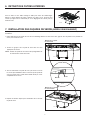
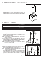
1. INSTALLATION DES CONDUITS
Déterminer à quel endroit et de quelle façon les conduits seront installés.
Un conduit droit et court permettra à votre hotte de fonctionner plus efficacement.
Installer des conduits de dimensions adéquates, des coudes et un capuchon de toit
ou de mur. Relier le conduit de métal au capuchon, puis acheminer le conduit jusqu’à
l’emplacement de votre hotte. Sceller les joints avec du ruban adhésif de métal de 2 po de
largeur.
Acheminer un câble d’alimentation électrique à 3 conducteurs jusqu’à l’emplacement de
la hotte.
Pour une meilleure évacuation des odeurs de cuisson, le bas de votre hotte devrait
être situé à un minimum de 30 po et à un maximum de 36 po au-dessus de la surface
de cuisson.
CONDUIT
DE 8 PO ROND
CAPUCHON DE TOIT
HOTTE
HH0152F
CONDUIT
DÉCORATIF
ADAPTATEUR/VOLET
DE
8 PO ROND
30 PO À 36 PO
AU-DESSUS
DE
LA SURFACE
DE CUISSON
HAUTEUR DU PLAFOND 8 PI 9 PI 10 PI*
D
ISTANCE MINIMALE RECOMMANDÉE
AU
-DESSUS DE LA SURFACE DE CUISSON
30 PO 30 PO 30 PO
DISTANCE MAXIMALE RECOMMANDÉE 34 PO 36 PO 36 PO
*Une rallonge de conduit décoratif est requise pour les plafonds de 10 pi, modèle
AEICB3SB (vendue séparément).
Une distance de plus de 36 po demeure à la discrétion de l’installateur et de l’utilisateur.
AVERTISSEMENT
!
Cette hotte est munie d’un récepteur radio (télécommande optionnelle vendue séparément). Tous changements ou
modifications qui ne sont pas approuvés par la partie responsable de la conformité pourraient annuler la possibilité
d’opérer l’équipement. La télécommande a été testée et est en accord avec les limites de la Classe B appareil
numérique et est conforme au chapitre 15 des règlements FCC et ICES-003 canadien. Ces limites sont développées
afin de fournir une protection raisonnable contre des interférences dommagables dans une installation résidentielle.
La télécommande génère, utilise et peut émettre des flux de fréquences radio qui peuvent causer des interférences
aux communications radio, si elle n’est pas installée selon les instructions. Cependant, il n’y a aucune garantie que
ces interférences ne se produiront pas dans une installation particulière. Si cet équipement est soupçonné causer
des interférences à un récepteur radio ou à un téléviseur, cela peut être confirmé en éteignant et rallumant l’appareil.
L’usager est encouragé à corriger cette situation en essayant les solutions suivantes :
• Réorienter ou relocaliser l’antenne réceptrice
• Augmenter la distance entre l’équipement et le récepteur
• Connecter l’équipement à une autre prise électrique ou à un disjoncteur différent de celui du récepteur
TABLE DES MATIÈRES
1. I NSTALLATION DES CONDUITS ........................................................................................................................................................................3
2. PRÉPARATION DE L’INSTALLATION ................................................................................................................................................................... 4
3. MESURE DE L'INSTALLATION .........................................................................................................................................................................4
4. INSTALLATION DU SUPPORT DE MONTAGE .........................................................................................................................................................5
5. ASSEMBLAGE DES ÉQUERRES .......................................................................................................................................................................6
6. RETRAIT DES FILTRES HYBRIDES ...................................................................................................................................................................7
7. I NSTALLATION DES FAÇADES DE VERRE (MODÈLE SBN SEULEMENT) .....................................................................................................................7
8. PRÉPARATION DE LA HOTTE .......................................................................................................................................................................8-9
9. INSTALLATION DE LA HOTTE ..................................................................................................................................................................... 9-10
10. BRANCHEMENT ÉLECTRIQUE ....................................................................................................................................................................... 11
11. RÉINSTALLATION DES FILTRES HYBRIDES ....................................................................................................................................................... 11
12. ÉCLAIRAGE À DEL .................................................................................................................................................................................. 12
13. ENTRETIEN ............................................................................................................................................................................................. 12
14. FONCTIONNEMENT ..............................................................................................................................................................................13-14
15. SCHÉMA ÉLECTRIQUE ............................................................................................................................................................................... 14
16. PIÈCES DE REMPLACEMENT ........................................................................................................................................................................ 15
17. GARANTIE .............................................................................................................................................................................................. 16

4
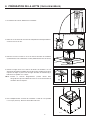
2. PRÉPARATION DE L’INSTALLATION
AVERTISSEMENT
VQ0010
!
Il est recommandé de porter des lunettes et des gants de sécurité lors de l’installation, de l’entretien et de la
réparation de cet appareil.
NOTE : Avant de commencer l’installation, vérifier le contenu de la boîte. Si des pièces sont manquantes ou endommagées, contacter
le manufacturier.
S’assurer que les éléments suivants sont inclus :
– Hotte
– Accessoires
• Ensemble de conduit décoratif (inférieur et supérieur)
• 2 filtres hybrides
• 1 support de montage (vissé sur le dessus de la hotte)
• 8 équerres
• 1 adaptateur/volet de 8 po rond (dans une boîte à part)
• Sac de pièces (collé sur le boîtier du ventilateur) incluant : 2 capuchons de connexion, 1 serre-fils, 8 vis à bois n
o
10 x 1½ po,
8 rondelles d’acier n
o
10, 10 vis quadrex n
o
8 x 3/8 po, 17 écrous n
o
10-32, 50 vis quadrex à tête hexagonale n
o
10-32 x 1/2 po,
2 vis Phillips n
o
8-1/2.
Pièces vendues séparément :
– Conduits, coudes, capuchons de mur ou de toit.
– Rallonge de conduit décoratif pour plafonds de 10 pi, modèle n
o
AEICB3SB.
– Télécommande optionnelle (modèle n
o
ACR3).
– Façades de verre pour le modèle ICB3I36SBN (voir les pièces de remplacement).
NOTE : Lors de l’installation, protéger la surface de cuisson et le comptoir de cuisine.
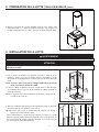
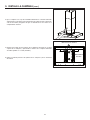
3. MESURE DE L’INSTALLATION
HH0157F
C
B
A
PLAFOND
SURFACE
DE
CUISSON
DESSUS
DU
BOÎTIER
DU
VENTILATEUR
12
3
⁄16 PO
C = B - A - 12
3
⁄16 PO
DESSOUS
DE
LA HOTTE
Déterminer la distance requise entre le plafond et le dessus du boîtier du
ventilateur (C) selon la hauteur du plafond (B) et la hauteur désirée de la hotte
au-dessus de la surface de cuisson (A).
NOTE : C = B - A - 12 3/16 po
La page est en cours de chargement...
La page est en cours de chargement...
La page est en cours de chargement...
La page est en cours de chargement...
La page est en cours de chargement...
La page est en cours de chargement...
La page est en cours de chargement...
La page est en cours de chargement...
La page est en cours de chargement...
La page est en cours de chargement...
La page est en cours de chargement...
La page est en cours de chargement...
La page est en cours de chargement...
La page est en cours de chargement...
La page est en cours de chargement...
La page est en cours de chargement...
La page est en cours de chargement...
La page est en cours de chargement...
La page est en cours de chargement...
La page est en cours de chargement...
La page est en cours de chargement...
La page est en cours de chargement...
La page est en cours de chargement...
La page est en cours de chargement...
La page est en cours de chargement...
La page est en cours de chargement...
La page est en cours de chargement...
La page est en cours de chargement...
-
 1
1
-
 2
2
-
 3
3
-
 4
4
-
 5
5
-
 6
6
-
 7
7
-
 8
8
-
 9
9
-
 10
10
-
 11
11
-
 12
12
-
 13
13
-
 14
14
-
 15
15
-
 16
16
-
 17
17
-
 18
18
-
 19
19
-
 20
20
-
 21
21
-
 22
22
-
 23
23
-
 24
24
-
 25
25
-
 26
26
-
 27
27
-
 28
28
-
 29
29
-
 30
30
-
 31
31
-
 32
32
-
 33
33
-
 34
34
-
 35
35
-
 36
36
-
 37
37
-
 38
38
-
 39
39
-
 40
40
-
 41
41
-
 42
42
-
 43
43
-
 44
44
-
 45
45
-
 46
46
-
 47
47
-
 48
48


Best ICB3I36SBN Guide d'installation
- Catégorie
- Hottes
- Taper
- Guide d'installation
dans d''autres langues
- English: Best ICB3I36SBN Installation guide
- español: Best ICB3I36SBN Guía de instalación