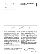
Brizo MultiChoice T75P688 Guide d'installation
- Catégorie
- Articles sanitaires
- Taper
- Guide d'installation
Ce manuel convient également à

92658 Rev. A
Pressure Balance
MultiChoice
®
Valve with
Integrated 3 or 6 Function
Diverter Trim
Installation Instructions
Owners Manual
T75P Series
Write purchased model number here.
Table of Contents:
Warranty ............................................................................. Page 2
Installation Instructions ....................................................... Pages 3 - 7
Maintenance ....................................................................... Page 8
Replacement Parts ............................................................. Pages 10 - 11
1
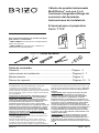
You May Need
CAUTION: This system/device must be set by the
installer to ensure safe, maximum temperature.
Any change in the setting may raise the discharge
temperature above the limit considered safe and
may lead to hot water burns.
NOTICE TO INSTALLER: CAUTION!–As the
installer of this valve, it is your responsibility
to properly INSTALL and ADJUST this valve
per the instructions given. This valve does
not automatically adjust for inlet temperature
changes, therefore, someone must make the
necessary temperature knob adjustments at
the time of installation and further adjustments
may be necessary due to seasonal water
temperature change. YOU MUST inform the
owner/user of this requirement by following the
instructions. If you or the owner/user are unsure
how to properly make these adjustments, please
refer to page 5 & 6 and if still uncertain, call us at
1-877-345-BRIZO (2749).
After installation and adjustment, you must afx
your name, company name and the date you
adjusted the temperature knob to the caution label
provided and apply or attach the label to the back
side of the closest cabinet door and the warning
label to the water heater. Leave this Instruction
Sheet for the owner’s/user’s reference.
WARNING: This thermostatic bath valve is
designed to minimize the effects of outlet water
temperature changes due to inlet pressure and
temperature changes, commonly caused by
dishwashers, washing machines, toilets and
the like. It may not provide protection from hot
water burns when there is a failure of other
temperature controlling devices elsewhere
in the plumbing system, if the temperature
knob is not properly set or if the hot water
temperature is changed after the settings
are made or if the water inlet changes due to
seasonal changes.
WARNING: Do not install a shut-off device on
either outlet of this valve. When this type of
device shuts off the water ow, it can defeat
the ability of the valve to balance the hot and
cold water pressures.
For easy installation of your Brizo
®
faucet you
will need:
• To READ ALL the instructions completely
before beginning.
• To READ ALL warnings,care, and
maintenance information.
02/27/17
T75P588-▲
T75P688-▲
3/32”

92658 Rev. A
2
Cleaning and Care
Care should be given to the cleaning
of this product. Although its nish is
extremely durable, it can be damaged by
harsh abrasives or polish. To clean, simply
wipe gently with a damp cloth and blot dry
with a soft towel.
Parts and Finish
All parts (other than electronic parts and batteries) and finishes of this Brizo
®
faucet are warranted to the original consumer purchaser to be
free from defects in material and workmanship for as long as the original consumer purchaser owns the home in which the faucet was first
installed or, for commercial users, for 5 years from the date of purchase.
Electronic Parts and Batteries (if applicable)
Electronic parts (other than batteries), if any, of this Brizo
®
faucet are warranted to the original consumer purchaser to be free from defects in
material and workmanship for 5 years from the date of purchase or, for commercial users, for one year from the date of purchase. No warranty
is provided on batteries.
Brizo Kitchen & Bath Company will replace, FREE OF CHARGE, during the applicable warranty period, any part or finish that proves defec-
tive in material and/or workmanship under normal installation, use and service. If repair or replacement is not practical, Brizo Kitchen & Bath
Company may elect to refund the purchase price in exchange for the return of the product. These are your exclusive remedies.
Brizo Kitchen & Bath Company recommends using a professional plumber for all installation and repair. We also recommend that you use only
genuine Brizo
®
replacement parts.
Brizo Kitchen & Bath Company shall not be liable for any damage to the faucet resulting from misuse, abuse, neglect or improper or incorrectly
performed installation, maintenance or repair, including failure to follow the applicable care and cleaning instructions.
Replacement parts may be obtained by calling the applicable number below or by writing to:
In the United States and Mexico: In Canada:
Brizo Kitchen & Bath Company Masco Canada Limited, Plumbing Group
Product Service Technical Service Centre
55 E. 111th Street 350 South Edgeware Road
Indianapolis, IN 46280 St. Thomas, Ontario, Canada N5P 4L1
1-877-345-BRIZO (2749) 1-877-345-BRIZO (2749)
Proof of purchase (original sales receipt) from the original purchaser must be made available to Brizo Kitchen & Bath Company for all warranty
claims unless the purchaser has registered the product with Brizo Kitchen & Bath Company. This warranty applies only to Brizo
®
faucets manu-
factured after January 1, 1995 and installed in the United States of America, Canada and Mexico.
BRIZO KITCHEN & BATH COMPANY SHALL NOT BE LIABLE FOR ANY SPECIAL, INCIDENTAL OR CONSEQUENTIAL DAMAGES
(INCLUDING LABOR CHARGES) FOR BREACH OF ANY EXPRESS OR IMPLIED WARRANTY ON THE FAUCET. Some states/provinces do
not allow the exclusion or limitation of special, incidental or consequential damages, so these limitations and exclusions may not apply to you.
This warranty gives you special legal rights. You may also have other rights which vary from state/province to state/province.
This is Brizo Kitchen & Bath Company’s exclusive written warranty and the warranty is not transferable.
If you have any questions or concerns regarding our warranty, please view our Warranty FAQs at www.Brizo.com, email us at [email protected] or
call us at the applicable number above.
Limited Warranty on Brizo
®
Faucets
© 2017 Masco Corporation of Indiana

92658 Rev. A
3
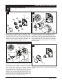
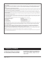
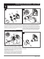
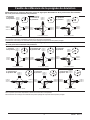
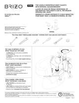
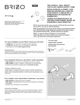
T75P Series Installation
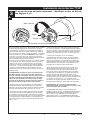
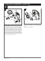
1
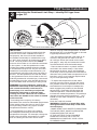
Cartridge Installation
A.
Turn off water supplies.
Remove cover (1),
bonnet nuts (2) and test caps (3) from the rough-
in body (4) (R75000). Place a bucket or small
container over the front of the valve body and
slowly open the water supplies to flush any
debris from the supply lines before installing the
cartridge. Turn the water supplies back off.
1
2
3
2
4
3
B.
Rotate the cartridge (1) so the words “hot side”
(2) appear on the left. Insert cartridge into valve
body as shown. Make sure the cartridge tubes
and O-rings (3) are properly seated in holes at the
base of the body. Ensure the keys on the body are
fully engaged with the slots in the body (4). A light
coating of plumbers grease applied to o-rings may
aid in assembly.
2
3
1
4
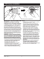
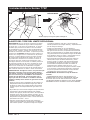
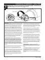
4
Thread bonnet nut (2) onto cartridge. Hand tighten
securely. Slide o-ring (1) over the cartridge and
bonnet.
C.
2
1
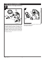
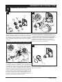
For back to back or reverse installations (hot on
right and cold on left) insert the cartridge (1) with
the “hot side” on the right. If you are not making
a reverse or back to back installation skip this
step and continue with step 1C. Apply silicone
lube to the three o-rings shown above to make
the cartridge easier to install and remove from the
rough-in body. Install the cartridge making sure
that the keys are fully engaged with the slot in the
rough-in body (see step B). Slide o-ring (3) and
bonnet nut (4) over the cartridge and thread onto
the rough-in body. Hand tighten securely.
Back to back Installation
Cold
Hot
Normal Installation
(changes not required)
Reverse
Installation
4
1
3
R75000

92658 Rev. A
4
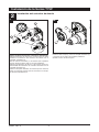
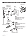
T75P Series Installation
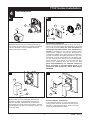
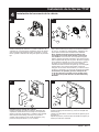
2
Diverter Cartridge Installation
Slip-On Installation
Slide bonnet nut (1) over diverter sleeve (2) and
thread into rough-in body.
Hand tighten securely.
B.
FOR DIVERTER CARTRIDGE INSTALLATION:
Apply silicone lube to the o-ring (2) to make
the diverter sleeve (3) easier to install diverter
cartridge. Rotate the diverter cartridge (1) so
the pin is at the bottom for proper installation.
Apply silicone lube to the o-rings (4) to make
the diverter sleeve (3) easier to install diverter
cartridge. Align diverter sleeve so that the
notches are in the same position as the notches
on rough-in body (5).
A.
3
1
5
2
1
2
5
4

92658 Rev. A
5
T75P Series Installation
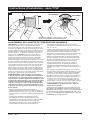
3
Adjusting the Rotational Limit Stop – Identify RLS type from
pages 5-6.
1st Position
Hotter
RLS with removable disc
Stem
Disc
IMPORTANT:
The Rotational Limit Stop is used to limit the
amount of hot water available such that, if
set properly, the user will not be scalded if
the handle accidentally is rotated all the way
to “hot” when a person is showering or lling
a tub. The rst position allows the LEAST
amount of hot water to mix with the cold water
in the system. In the rst position the water
will be the coldest possible when the handle
is turned all the way to hot. As you move the
Rotational Limit Stop counterclockwise, you
progressively add more and more hot water in
the mix. The last position to the left will result
in the greatest amount of hot water to the mix,
and the greatest risk of scald injury if someone
accidentally turns the valve handle all the way
to the hot side while showering or lling a tub.
WARNING: In some instances, setting the
Rotational Limit Stop in the hottest position
(full counterclockwise) could result in
scald injury. It is necessary to adjust the
Rotational Limit Stop so that the water
coming out of the valve will not scald the
user when the handle of the valve is rotated
to the hot side.
• According to the majority of industry
standards, the maximum allowable temperature
of the water exiting the valve is 120°F (Your
local plumbing codes may require a water
temperature less than 120°F).
• The Rotational Limit Stop may need to
be readjusted seasonally if the inlet water
temperature changes. For example, during the
winter, the cold water temperature is colder
than it is during the summer which could
result in varying outlet temperatures. A water
temperature for a comfortable bath or shower
is typically between 90°F - 110°F.
• Run the water so that the cold water is as
cold as it will get and hot water is as hot
as it will get. Place the handle on the stem
(see page 7, step 4D) and rotate the handle
counterclockwise until the handle stops.
• Place a thermometer in a plastic tumbler
and hold in the water stream. If the water
temperature is above 120°F, the Rotational
Limit Stop must be repositioned clockwise to
decrease valve outlet water temperature to be
less than 120°F or to meet the requirements
of your local plumbing codes.
• To adjust the temperature of the water
coming out of the valve, pull the disc back
to a position where it is possible to remove
the Rotational Limit Stop and readjust the
teeth engagement position to the desired
temperature. Clockwise will decrease the
outlet temperature, counterclockwise will
increase the outlet temperature. Temperature
change per tooth (notch) could be 4° - 16°F
based on inlet water conditions. Repeat as
necessary.
Push disc until fully seated.
WARNING: Failure to re-install Disc after
setting Rotational Limit Stop could result
in scald injury.
• MAKE SURE COLD WATER FLOWS FROM
THE VALVE FIRST. MAKE SURE WATER
FLOWING FROM THE VALVE
AT THE HOTTEST FLOW POSSIBLE
DOES NOT EXCEED 120°F OR THE
MAXIMUM ALLOWED BY YOUR LOCAL
PLUMBING CODE.
A.

92658 Rev. A
6
Hotter
B.
T75P Series Installation
1
1
HOTTER
MÁS CALIENTE
PLUS CHAUD
COLDER
MÁS FRÍA
PLUS FROID
RLS with pull/turn adjustment
ADJUSTING THE ROTATIONAL LIMIT STOP
IMPORTANT: The Rotational Limit Stop
is used to limit the amount of hot water
available such that, if set properly, a scald injury
is less likely to occur if the handle accidentally
is rotated all the way to “hot” when a person
is showering or lling a tub. The rst position
allows the LEAST amount of hot water to
mix with the cold water in the system. In the
rst position the water will be the coldest
possible when the handle is turned all the way
to hot. As you move the Rotational Limit Stop
counterclockwise, you progressively add more
and more hot water in the mix. The last position
to the left will result in the greatest amount of
hot water to the mix, and the greatest risk of
scald injury if someone accidentally turns the
valve handle all the way to the hot side while
showering or lling a tub.
WARNING: In some instances, setting the
Rotational Limit Stop in the hottest position
(full counterclockwise) could result in scald
injury. It is necessary to adjust the Rotational
Limit Stop so that the water coming out of
the valve will not scald the user when the
handle of the valve is rotated to the hot side.
• According to the majority of industry standards,
the maximum allowable temperature of the
water exiting the valve is 120°F (Your local
plumbing codes may require a water
temperature less than 120°F).
• The Rotational Limit Stop may need to be
re-adjusted seasonally if the inlet water
temperature changes. For example, during the
winter, the cold water temperature is colder
than it is during the summer which could
result in varying outlet temperatures. A water
temperature for a comfortable bath or shower
is typically between 90°F - 110°F.
• Run the water so that the cold water is as
cold as it will get and hot water is as hot as
it will get. Place the handle on the stem (see
page 9, step 4F) and rotate the handle coun-
terclockwise until the handle stops.
• Place a thermometer in a plastic tumbler
and hold in the water stream. If the water
temperature is above 120°F, the Rotational
Limit Stop must be repositioned clockwise to
decrease valve outlet water temperature to be
less than 120°F or to meet the requirements of
your local plumbing codes.
• To adjust the temperature of the water coming
out of the valve, pull the white Rotational
Limit Stop (1) outward and rotate. Clockwise
rotation will decrease the outlet temperature,
counterclockwise rotation will increase the
outlet temperature. Temperature change per
tooth (notch) could be 4° - 16°F based on inlet
water conditions. Repeat as necessary. When
finished, make sure that the Rotational Limit
Stop is fully retracted into the seated position.
WARNING: Do not take the Rotational Limit
Stop apart.
• MAKE SURE COLD WATER FLOWS FROM
THE VALVE FIRST. MAKE SURE WATER
FLOWING FROM THE VALVE AT THE
HOTTEST FLOW POSSIBLE DOES NOT
EXCEED 120°F OR THE MAXIMUM ALLOWED
BY YOUR LOCAL PLUMBING CODE.

92658 Rev. A
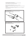
D.
2
1
3
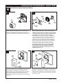
Diverter Handle Installation
Insert diverter handle (1) onto trim sleeve (2).
Using a allen wrench, insert set screw (3) into
handle (1). Applying pressure, insert set screw
cover (4) until properly seated.
4
7
T75P Series Installation
Trim Sleeve Installation
Slide trim sleeve (1) over cartridge, bonnet (2),
and O-ring. Ensure sleeve is properly positioned
over the cartridge. O-ring will help keep trim
sleeve securely in position.
1
2
A.
4
Trim Installation
Escutcheon Installation
Secure backplate (2) to rough-in body (3) using 4
screws (4) provided. Ensure backplate is oriented
front side forward.
Note: Be sure backplate is
oriented front side forward and markings are
visible
. If mounting to an uneven surface, apply
appropriate sealant around the backplate to
supplement rubber seal. Align holes in escutcheon
(5) with cartridges and slide escutcheon (5) onto
backplate. Secure escutcheon by threading trim
nut (6) onto diverter sleeve. Do not overtighten.
Slide diverter trim sleeve (7) over trim nut and
secure into position with set screw (8).
For
thick wall installation, an optional extension
kit is available to accommodate up to 1" of
additional wall thickness. Order RP91024 &
RP92548.
B.
4
2
3
5
6
7
8
Valve Handle Installation
Slide handle (9) over cartridge, aligning at
surfaces inside handle with at surfaces on
side of cartridge. Handle lever should point
downward (6 o'clock) in the off position. Secure
handle with set screw (10) and press button (11)
cover into hole.
9
10
11
C.

92658 Rev. A
Potential scald or thermal shock injury could result due to cross ow if outlet at
the shower is blocked or restricted (e.g., pause control on showerhead). Be sure
to point showerhead away from you when re-starting ow or install inlet check
valves on both supply lines to prevent possible injury.
5
Faucet leaks from tub spout/showerhead:
SHUT OFF WATER SUPPLIES.
Replace seats and springs–Repair
Kit RP4993. Check condition of lower O-rings
and replace if necessary RP14414. See
Helpful Hints 1, 2, & 3.
If leak persists:
SHUT OFF WATER SUPPLIES.
Replace valve cartridge RP46074.
See Helpful Hints 1, 2, 3 & 5.
Unable to maintain constant
water temperature:
Replace valve cartridge RP46074 or follow
instructions in Helpful Hints 1, 2, 4 & 5.
Helpful Hints:
1. Before removing valve cartridge assembly
for any maintenance, be sure to note the
position of the rotational limit stop on the cap.
The valve cartridge assembly must always be
put back in the same position. BE SAFE! After
you have nished the installation, turn on
valve to make sure COLD WATER FLOWS
FIRST.
2. To remove valve cartridge from body, shut
off water supplies and remove handle and
bonnet nut. Do not pry the valve cartridge
out of the body with a screwdriver. Place
handle on stem and rotate counterclockwise
approximately 1/4 turn after the stop has
been contacted. Lift valve cartridge out of
body.
3. To remove seats and springs, remove
valve cartridge. Separate cap assembly
from the housing assembly by rotating
the cap assembly counterclockwise 90
o
(degrees). Separate cap and housing
assemblies. Remove seats and springs and
replace. Place the largest diameter of the
spring into the seat pocket rst and then
press the tapered end of the seal over the
spring. Reassemble valve cartridge and
replace in body following instructions given
in 1 above.
4. If the water in your area has lime,
rust, sand or other contaminants in it,
your pressure balance valve will require
periodic inspection. The frequency of the
inspection will depend on the amount of
contaminants in the water. To inspect valve
cartridge remove it and follow the steps in
note 1 above. Turn the valve to the full mix
position and shake the cartridge vigorously.
If there is a rattling sound, the unit is
functional and can be reinstalled following
instructions given in note 1 above. If
there is no rattle, replace valve cartridge
RP46074.
5. Push disc until fully seated. See page 5
for more details.
T75P Series Maintenance
8

92658 Rev. A
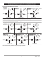
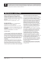
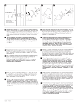
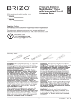
Diverter Handle Reference Sheet
2nd Position ✱
2 ª Posición ✱
2e position ✱
3rd Position
3 ª posición
3e position
1st Position
1 ª posición
1ère position
2nd Position ✱✱
2 ª Posición ✱✱
2e position ✱✱
3rd Position
3 ª posición
3e position
Outlet 1
Salida 1
Sortie 1
Outlet 2
Salida 2
Sortie 2
Outlet 3
Salida 3
Sortie 3
In / Entrada / Entrée
4th Position ✱✱
4 ª posición ✱✱
4e position ✱✱
5th Position
5 ª posición
5e position
6th Position ✱✱
6 ª posición ✱✱
6e position ✱✱
Water Flow For 3 Function Diverter / Flujo de agua para Desviadores de 3 posiciones / Écoulement
de l’eau pour les inverseurs à 3 positions
Water Flow For 6 Function Diverter / Flujo de agua para Desviadores de 6 posiciones / Écoulement
de l’eau pour les inverseurs à 6 positions
In / Entrada / Entrée In / Entrada / Entrée
In / Entrada / Entrée
In / Entrada / Entrée
In / Entrada / Entrée
Outlet 1
Salida 1
Sortie 1
Outlet 2
Salida 2
Sortie 2
Outlet 3
Salida 3
Sortie 3
Outlet 1
Salida 1
Sortie 1
Outlet 2
Salida 2
Sortie 2
Outlet 3
Salida 3
Sortie 3
Outlet 1
Salida 1
Sortie 1
Outlet 2
Salida 2
Sortie 2
Outlet 3
Salida 3
Sortie 3
Outlet 1
Salida 1
Sortie 1
Outlet 2
Salida 2
Sortie 2
Outlet 3
Salida 3
Sortie 3
Outlet 1
Salida 1
Sortie 1
Outlet 2
Salida 2
Sortie 2
Outlet 3
Salida 3
Sortie 3
Outlet 1
Salida 1
Sortie 1
Outlet 2
Salida 2
Sortie 2
Outlet 3
Salida 3
Sortie 3
Outlet 1
Salida 1
Sortie 1
Outlet 2
Salida 2
Sortie 2
Outlet 3
Salida 3
Sortie 3
Outlet 1
Salida 1
Sortie 1
Outlet 2
Salida 2
Sortie 2
Outlet 3
Salida 3
Sortie 3
In / Entrada / Entrée
In / Entrada / Entrée
In / Entrada / Entrée
✱✱ Shared positions do not exist in non-shared cartridges.
✱✱ Los ajustes o posiciones compartidas no existen en los cartuchos no-compartidos.
✱✱ Comme leur nom l’indique, les cartouches sans position partagée ne comportent aucune position partagée.
✱ Shared positions do not exist in non-shared cartridges.
✱ Los ajustes o posiciones compartidas no existen en los cartuchos no-compartidos.
✱ Comme leur nom l’indique, les cartouches sans position partagée ne comportent aucune position partagée.
1st Position
1 ª posición
1ère position
9

92658 Rev. A
02/27/17

92658 Rev. A
Válvula de presión balanceada
MultiChoice
®
con con 3 o 6
funciones integradas Manga de
accesorio del desviador
Instrucciones de instalación
El manual para el propietario
Serie T75P
Escriba el número del modelo comprado.
Tabla de contenido:
Garantía ........................................................................... Página 2
Instrucciones de instalación ............................................. Páginas 3 - 7
Mantenimiento .................................................................. Página 8
Piezas de repuesto .......................................................... Páginas 10 - 11
1
Puede necesitar
ADVERTENCIA: Este sistema/dispositivo debe estar
congurado por el instalador para asegurar una
temperatura máxima segura. Cualquier cambio en el ajuste
puede aumentar la temperatura de descarga por encima del
límite considerado seguro y puede resultar en quemaduras
por agua caliente.
AVISO PARA EL INSTALADOR: ¡ATENCIÓN! Como el
instalador de esta válvula, es su responsabilidad de
INSTALAR y AJUSTAR correctamente esta válvula
según las instrucciones proporcionadas. Esta válvula
no se ajusta automáticamente a los cambios de
temperatura de entrada, por lo tanto, alguien debe
hacer los ajustes necesarios con la perilla de control de
temperatura en el momento de la instalación y ajustes
adicionales pueden ser necesarios debido a cambios
estacionales de la temperatura del agua. USTED DEBE
informar al propietario/ usuario de este requisito
siguiendo las instrucciones. Si usted o el dueño/
consumidor no está seguro de como hacer estos ajustes,
consulte la página 5 y 6 y si aún tiene duda, llámenos al
1-877-345-BRIZO (2749).
Después de la instalación y el ajuste, debe colocar su
nombre, nombre de la empresa y la fecha en que ajustó
la perilla de control de la temperatura a la etiqueta de
precaución proporcionada y aplique o pegue la etiqueta en
la parte trasera de la puerta del armario más cercano y la
etiqueta de advertencia al calentador de agua. Deje esta
hoja de instrucciones para referencia del propietario
/usuario.
ADVERTENCIA: Esta válvula termostática de baño
está diseñada para minimizar los efectos de los
cambios de temperatura del agua de salida debido
a cambios de presión y temperatura, causados
habitualmente por los lavaplatos, las lavadoras, los
inodoros y otros aparatos similares. Puede no ofrecer
protección contra las quemaduras por agua caliente
cuando hay un fallo de otros dispositivos para el
control de temperatura en otras partes del sistema de
plomería, si la perilla para el control de la temperatura
no está congurada correctamente o si se cambia
la temperatura del agua caliente después de realizar
los ajustes o si el agua admisión cambia debido a los
cambios estacionales.
ADVERTENCIA: No instale un dispositivo de cierre
en cualquiera de las tuberías de salida de agua de
esta válvula. Cuando este tipo de dispositivo cierra
el ujo del agua, pueda aminorar el propósito de la
válvula para balancear las presiones del agua caliente
y fría.
Para una fácil instalación de su llave de agua/
grifo Brizo
®
va a necesitar:
• LEER TODAS las instrucciones completamente
antes de comenzar.
• LEER TODAS las advertencias, cuidados, e
información de mantenimiento.
02/27/17
3/32” & 1/8”
T75P588-▲
T75P688-▲

92658 Rev. A
2
Limpieza y Cuidado
Se debe tener cuidado con la limpieza
de este producto. Aunque su acabado
es extremadamente resistente, puede
ser dañado por abrasivos o pulimentos
ásperos. Para limpiar, simplemente frote
con un paño húmedo y seque con una
toalla suave.
Piezas y Acabado
Todas las piezas (menos las piezas electrónicas y las pilas) y acabados de esta llave de agua - grifo Brizo® están garantizados al consumidor
comprador original, de estar libres de defectos en materiales y mano de obra durante el tiempo que el comprador original sea dueño de la
casa en la cual la llave de agua fue instalada por primera vez o, para los usuarios comerciales, por cinco (5) años desde la fecha de
compra.
Piezas electrónicas y las baterías/pilas (si aplicable)
Las piezas electrónicas (excepto las baterías), sea el caso, de este grifo Brizo® están garantizadas al consumidor comprador original, de estar
libres de defectos en materiales y mano de obra durante 5 años desde la fecha de compra o, para los usuarios comerciales, durante un año
desde la fecha de compra. La garantía no cubre las baterías.
Brizo Kitchen & Bath Company reparará o reemplazará, SIN COSTO ALGUNO, durante el período de garantía aplicable, cualquier pieza o
acabado que presente defectos en materiales y/o mano de obra bajo instalación, uso y servicio normal. Si la reparación o sustitución no es
práctica, Brizo Kitchen & Bath Company podrá optar reintegrarle el precio de la compra a cambio de la devolución del producto. Estos son
sus únicos recursos.
Brizo Kitchen & Bath Company recomienda que use un plomero profesional para todas las instalaciones y reparación. También recomienda
que utilice sólo piezas de repuesto Brizo
®
.
Brizo Kitchen & Bath Company no será responsable de cualquier daño a la llave de agua/grifo resultante del uso indebido, abuso, negligencia
o uso inapropiado o instalación realizada de forma incorrecta, mantenimiento o reparación, incluyendo el no seguir las instrucciones de cui-
dado y limpieza aplicables.
Las piezas de repuesto se pueden obtener llamando al número que figura más abajo o escribiendo a:
En los Estados Unidos y Mexico: En Canadá:
Brizo Kitchen & Bath Company Masco Canada Limited, Plumbing Group
Product Service Technical Service Centre
55 E. 111th Street 350 South Edgeware Road
Indianapolis, IN 46280 St. Thomas, Ontario, Canada N5P 4L1
1-877-345-BRIZO (2749) 1-877-345-BRIZO (2749)
La prueba de compra (recibo original de venta) del comprador original debe ponerse a la disposición de Brizo Kitchen & Bath Company para
todos los reclamos de garantía a menos que el comprador haya registrado el producto con Brizo Kitchen & Bath Company. Esta garantía
se aplica solamente a las llaves de agua/grifos Brizo
®
fabricadas después de 1 de enero de 1995 e instalados en los Estados Unidos de
América, Canadá y México.
BRIZO KITCHEN & BATH COMPANY NO SERÁ RESPONSABLE POR DAÑOS ESPECIALES, INCIDENTALES O CONSECUENTES
(INCLUYENDO CARGOS DE LABOR) YA SEAN RESULTANTES DEL INCUMPLIMIENTO DE CUALQUIER GARANTÍA EXPRESA O
IMPLÍCITA DE LA LLAVE DE AGUA/GRIFO. Algunos estados/provincias no permiten la exclusión o limitación de daños especiales, inciden-
tales o consecuentes, por lo que estas limitaciones y exclusiones pueden no aplicarle en su caso.
Esta garantía le otorga derechos legales especiales, y usted también puede tener otros derechos que varían de estado/provincia a estado/
provincia.
Esta es la garantía exclusiva por escrito de Brizo Kitchen & Bath Company’s, y la garantía no es transferible.
Si usted tiene alguna pregunta o inquietud acerca de nuestra garantía, por favor vea nuestra sección de Preguntas Frecuentes sobre la garantía www.
Brizo.com, email us at [email protected].
Garantía Limitada de las llaves de agua/grifos Brizo
®
© 2017 Masco Corporación of Indiana

92658 Rev. A
3
Instalación de la Series T75P
1
Instalación del cartucho
A.
Cierre los suministros de agua.
Quite la tapa (1), las
tuercas tapas (2) y las tapas de prueba (3) del cuerpo de
la tubería preliminar detrás de la pared (4). Coloque una
cubeta o recipiente pequeño sobre el frente del cuerpo
de la válvula y abra lentamente los suministros de agua
para eliminar cualquier residuo de las líneas de suministro
antes
de instalar el cartucho. Cierre otra vez el agua de
suministro.
1
2
3
2
4
3
B.
Gire el cartucho (1) de modo que las palabras "hot side”
lado caliente (2) aparezcan a la izquierda. Inserte en el
cuerpo de la válvula como se muestra. Asegúrese de que
los tubos del cartucho y las juntas tóricas (3) estén bien
colocadas en los oricios de la base del cuerpo. Asegúrese
de que las muescas del cuerpo estén completamente
acopladas con las ranuras del cuerpo (4). Un ligero
recubrimiento de grasa de plomero aplicado a las juntas
tóricas puede ayudar en el ensamblaje.
2
3
1
4
4
Enrosque la tuerca tapa (2) en el cartucho. Apriete a
mano de forma segura. Deslice la junta tórica (1) sobre el
cartucho y el casquete.
C.
2
1
Para instalaciones de dorso con dorso o inversas (caliente
a la derecha y fría a la izquierda) inserte el cartucho (1)
con el lado "caliente" en la derecha. Si no está haciendo
una instalación inversa o dorso con dorso, omita este paso
y continúe con el paso 1C. Aplique lubricante de silicona
a las tres juntas tóricas mostradas arriba para facilitar la
instalación del cartucho y retirar del cuerpo de la tubería
interna o prelimiar. Instale el cartucho asegurándose de
que las muescas estén completamente acopladas con la
ranura en el cuerpo de la tubería interna (Véase el paso
B). Deslice la junta tórica (3) y la tuerca tapa (4) sobre el
cartucho y enrosque en el cuerpo de la tubería interna o
detrás de la pared. Apriete jamente a mano.
Instalación de dorso con dorso.
Fría
Caliente
Instalación normal
(no se requieren cambios)
Instalación
inversa
4
1
3

92658 Rev. A
4
Instalación de la Series T75P
2
Instalación del cartucho de desvío
Instalación deslizable
Deslice la tuerca tapa (1) sobre el casquillo desviador (2)
y enrosque en el cuerpo de la tubería preliminar.
Apriete a mano de forma segura.
B.
PARA LA INSTALACIÓN DEL CARTUCHO DE DESVÍO:
Aplique lubricante de silicona a la junta tórica (2) para
facilitar la instalación del cartucho desviador con el
casquillo desviador (3).
Gire el cartucho desviador (1) de manera que el pasador
esté en la parte inferior para su correcta instalación.
Aplique el lubricante de silicona a las juntas tóricas (4)
para facilitar la instalación del cartucho desviador con el
casquillo desviador (3).
Alinee el casquillo desviador de manera que las muescas
están en la misma posición que las muescas en el cuerpo
de la tubería preliminar (5).
A.
3
1
5
2
1
2
5
4

92658 Rev. A
5
Instalación de la Series T75P
3
El ajuste del tope del límite rotacional – Identique el tipo de RLS de
las páginas 5 y 6.
1ra posición
Más caliente
RLS (tope) con disco desmontable
Espiga
Disco
IMPORTANTE:
El tope del límite rotacional se utiliza para limitar la cantidad
de agua caliente disponible de manera que si se ajusta
correctamente, el usuario no se escaldará si la manija se
gira accidentalmente hasta el lado caliente “hot” mientras
que una persona se ducha o se llena la bañera. La primera
posición permite que la cantidad MENOR de agua caliente
se mezcle con el agua fría en el sistema. En la primera
posición el agua es lo más fría posible cuando la manija se
gira completamente hacia el lado caliente.
Al mover el tope del límite rotacional en el sentido contrario
a las agujas del reloj, añade progresivamente más agua
caliente en la mezcla. La última posición a la izquierda
resultará en la mayor cantidad de agua caliente añadida
a la mezcla, y el mayor riesgo de lesión por escaldadura
si alguien accidentalmente gira la manija de la válvula
completamente hacia el lado caliente mientras se ducha o
llena la bañera.
ADVERTENCIA: En algunos casos, el ajuste del tope
del límite rotacional en la posición más caliente (en
sentido contrario a las agujas del reloj) podría provocar
lesiones resusltantes de escaldaduras. Es necesario
ajustar el tope del límite rotacional para que el agua
que sale de la válvula no escalde al usuario cuando la
manija de la válvula se gira hacia el lado caliente.
• Según la mayoría de los estándares de la industria, la
temperatura máxima permitida del agua que sale de la
válvula es 120°F (Sus códigos locales de plomería pueden
requerir una temperatura del agua menor de 120° F).
• Es posible que sea necesario reajustar el tope de límite
rotacional si cambia la temperatura del agua de entrada.
Por ejemplo, durante el invierno, la temperatura del agua
fría es más fría que durante el verano, lo que podría resultar
en temperaturas de salida variables. La temperatura del
agua para un baño o ducha cómoda es típicamente entre
90° F - 110° F.
• Deje que el agua fluya para que el agua fría salga tan
fría como sea posible y el agua caliente salga tan caliente
como sea posible. Coloque la manija en la espiga (vea la
página 7, paso 4D) y gire la manija en sentido contrario a
las agujas del reloj hasta que ya no se pueda girar más.
• Coloque un termómetro en un vaso plástico y
manténgalo bajo el chorro de agua. Si la temperatura
del agua es más de 120°F, el tope del límite rotacional
debe ser reposicionado en el sentido de las agujas del
reloj para disminuir la temperatura del agua de la salida
de la válvula a menos de 120°F o para cumplir con los
requisitos de los códigos locales de plomería.
• Para ajustar la temperatura del agua que sale de la
válvula, hale el disco hacia atrás a una posición en la
que sea posible retirar el tope del límite rotacional y
reajustar la posición de acoplamiento de los dentados
a la temperatura deseada. En el sentido de las agujas
del reloj disminuirá la temperatura de salida, en el
sentido contrario al de las agujas del reloj, aumentará la
temperatura del agua de salida. El cambio de temperatura
por dentado podría ser de 4° - 16° F basado en las
condiciones del agua de entrada. Repita si es necesario.
Empuje el disco hasta que quede totalmente asentado.
ADVERTENCIA: Si no vuelve a instalar el disco
después de ajustar el tope del límite rotacional, podría
producir lesiones por escaldado.
• ASEGÚRESE DE QUE EL AGUA FRÍA FLUYA
PRIMERO DE LA VÁLVULA. ASEGÚRESE DE QUE LA
TEMPERATURA DEL AGUA CALIENTE QUE FLUYE
DE LA VÁLVULA AL MÁXIMO FLUJO CALIENTE
NO EXCEDA 120°F O LA TEMERATURA MÁXIMA
PERMITIDA POR SU CÓDIGO LOCAL DE PLOMERÍA.
A.

92658 Rev. A
6
Instalación de la Series T75P
B.
1
1
MÁS CALIENTE
MÁS FRÍA
A.RLS (tope) con ajuste para halar/girar
AJUSTE DEL TOPE DEL LÍMITE ROTACIONAL
IMPORTANTE: El tope del límite rotacional se utiliza
para limitar la cantidad de agua caliente disponible
de modo que, si se ajusta correctamente, es menos
probable que produzca una lesión como resultado
de escaldadura si la manija se gira accidentalmente
hacia el lado “caliente” cuando una persona se está
duchándo o llenando una bañera. La primera posición
permite que la MENOR cantidad de agua caliente se
mezcle con el agua fría en el sistema. En la primera
posición, el agua saldrá lo más fría posible cuando
la manija está completamente abierta. Al mover el
tope del límite rotacional en el sentido contrario a
las agujas del reloj, añade progresivamente más y
más agua caliente en la mezcla. La última posición a
la izquierda resultará en la mayor cantidad de agua
caliente añadida a la mezcla, y el mayor riesgo de
lesión como resultado de escaldadura si alguien
accidentalmente gira la manija de la válvula hasta el
lado caliente mientras se ducha o llena una bañera.
ADVERTENCIA: En algunos casos, el ajuste del tope
del límite rotacional en la posición más caliente
(en sentido contrario a las agujas del reloj) podría
provocar lesiones por escaldadura. Es necesario
ajustar el tope del límite rotacional para que el
agua que sale de la válvula no escalde al usuario
cuando la manija de la válvula se gira hacia el lado
caliente.
• Según la mayoría de los estándares de la industria, la
temperatura máxima permisible del agua que sale de
la válvula es 120°F (Sus códigos locales de plomería
pueden requerir una temperatura del agua menor de
120°F).
• Es posible que sea necesario reajustar el tope del límite
rotacional si la la temperatura del agua de entrada
cambia. Por ejemplo, durante el invierno, la temperatura
del agua fría es más fría que durante el verano, lo que
podría resultar en temperaturas de salida variables. La
temperatura del agua para un baño o ducha cómoda es
típicamente entre 90°F - 110°F.
• Deje que el agua fluya de manera que el agua fría
esté lo más fría posible que pueda estar y la caliente lo
más caliente posible. Coloque la manija en la espiga
(consulte la página 9, paso 4F) y gire la manija en
sentido opuesto a las manijas del reloj – izquierda hasta
que la manija se detenga.
• Coloque un termómetro en un vaso plástico y
manténgalo bajo el chorro de agua. Si la temperatura
del agua es más de 120°F, el tope del límite rotacional
debe ser reposicionado en el sentido de las agujas del
reloj para disminuir la temperatura del agua de la salida
de la válvula a menos de 120°F o para cumplir con los
requisitos de los códigos lcoales de plomería.
• Para ajustar la temperatura del agua que sale de la
válvula, hale el tope del límite rotacional (1) hacia
afuera y gírela. La rotación a la derecha disminuirá
la temperatura de salida, la rotación a la izquierda
incrementará la temperatura salida. El cambio de
temperatura por dentado podría ser de 4° - 16°F
basado en las condiciones del agua de entrada. Repita
si es necesario. Cuando haya terminado, asegúrese
de que el tope del límite rotacional se haya retraído
completamente hacia la posición sentada.
ADVERTENCIA: No desarme el tope de límite de
rotación.
• ASEGÚRESE DE QUE EL AGUA FRÍA FLUYA
PRIMERO DE LA VÁLVULA. ASEGÚRESE DE QUE
EL AGUA QUE FLUYE DE LA VÁLVULA LO MÁS
CALIENTE POSIBLE NO EXCEDA 120°F NI EL MÁXIMO
PERMITIDO POR SU CÓDIGO LOCAL DE PLOMERÍA.
MÁS CALIENTE

92658 Rev. A
7
Instalación del desviador de la manija
Inserte la manija del desviador (1) sobre el casquillo del
accesorio (2).
Usando una llave allen, inserte el tornillo de jación (3) en
la manija (1).
Aplicando presión, inserte la tapa del tornillo de ajuste (4)
hasta que esté bien asentada.
Instalación de la Series T75P
Instalación de la manga de accesorio
Deslice la manga de accesorio (1) sobre el cartucho, el
casquete (2) y la junta tórica. Asegúrese de que la manga
esté colocada correctamente sobre el cartucho. La junta
tórica ayudará a mantener la manga de ajuste en posición
ja.
1
2
A.
4
Instalación del accesorio de la válvula
Instalación de la chapa de cubierta
Fije la placa trasera (2) al cuerpo de la tubería prelimiar
(3) con los 4 tornillos (4) suministrados. Asegúrese de
que la placa trasera esté orientada hacia adelante.
Nota: Asegúrese de que la placa posterior esté
orientada con el frente hacia delante y las marcas
son visibles.
Si se monta en una supercie irregular,
aplique sellador apropiado alrededor de la placa trasera
para complementar la junta de goma. Alinee los agujeros
en la chapa de cubierta (5) con los cartuchos y deslice
la chapa (5) en la placa trasera. Fijee la chapa de
cubierta roscando la tuerca de ajuste (6) en el manguito
del desviador. No lo apriete demasiado. Deslice el
manguito de accesorio del desviador (7) sobre la tuerca
de ajuste y asegúrelo con el tornillo de jación (8).
Para
la instalación en paredes gruesas, se dispone de
un kit de extensión opcional para acomodar hasta
1" de grosor de pared adicional. Ordene RP91024 y
RP92548.
B.
5
2
3
4
7
8
6
Instalación de la manija de la válvula
Deslice la manija (9) sobre el cartucho, alineando las
supercies planas dentro de la manija con supercies
planas en el lado del cartucho. La palanca de la manija
debe apuntar hacia abajo (6 horas) en la posición
cerrada. Fije la manija con el tornillo de jación (10) y
presione la tapa del botón (11) en el oricio.
C.
9
10
11
D.
2
1
3
4

92658 Rev. A
Existe la posibilidad de lesión por escaldadura o de choque térmico resultante de un ujo cruzado en el
caso que la salida de la regadera/ducha está bloqueada o restringida (por ejemplo, pause el control de la
cabeza de la regadera/ducha). Asegúrese de apuntar la regadera/ducha alejado de usted cuando vuelva
a iniciar el ujo o instale las válvulas de retención de la entrada en ambas líneas de suministro para evitar
posibles lesiones.
Mantenimiento de la Series T75P
5
8
Si el agua se ltra por la llave de agua de la regadera:
CIERRE LOS SUMINISTROS DE AGUA
Reemplace asientos y resortes –Juego de piezas de
repuesto RP4993. Verique el estado de las juntas tóricas
inferiores y, si es necesario, reemplácelas RP14414.
Consulte Sugerencias útiles 1, 2 y 3.
Si la fuga persiste:
CIERRE LOS SUMINISTROS DE AGUA.
Reemplace el cartucho de la válvula RP46074. Consulte
Sugerencias útiles 1, 2, 3 y 5.
Incapaz de mantener constante la temperatura del agua:
Reemplace el cartucho de la válvula RP46074 o siga las
instrucciones en Consejos útiles 1, 2, 4 y 5.
Sugerencias útiles:
1. Antes de retirar el ensamble del cartucho de la válvula
para hacer cualquier mantenimiento, asegúrese de tomar
nota de la posición del tope del límite rotacional en la tapa. El
ensamble del cartucho de la válvula debe siempre colocarse
otra vez en la misma posición. ¡CUIDESE! Después de haber
terminado la instalación, abra la válvula para asegurarse de
que el AGUA FRÍA FLUYE PRIMERO.
2. Para retirar el cartucho de la válvula del cuerpo, cierre
el suministro de agua y retire la manija y la tuerca tapa.
No extraiga el cartucho de la válvula del cuerpo con un
destornillador. Coloque la manija sobre la espiga y gírela
aproximadamente 1/4 de vuelta en sentido contrario a las
agujas del reloj después de haber tropezado al tope del
límite. Levante el cartucho de la válvula hacia afuera del
cuerpo.
3. Para retirar los asientos y resortes, retire el cartucho de
la válvula. Separe el ensamble de la tapa del ensamble
(piezas) del bastidor girando el ensamble de la tapa
90º (grados) en sentido contrario a las agujas del reloj.
Separe los ensambles o piezas, de la tapa y del bastidor.
Retire los asientos y resortes y reemplácelos. Primero
coloque el diámetro más grande del resorte en el lugar
del asiento y luego presione el extremo cónico del sello
sobre el resorte. Vuelva a montar el cartucho de la válvula
y cambie el cuerpo siguiendo las instrucciones indicadas
en el punto 1.
4. Si el agua de su área tiene cal, óxido, arena u otros
contaminantes, la válvula para balancear la presión
requerirá inspección periódica. La frecuencia de la
inspección dependerá de la cantidad de contaminantes
en el agua. Para inspeccionar el cartucho de la válvula,
extráigalo y siga los pasos en la Nota 1 anterior. Gire
la válvula a la posición de mezcla completa y agite el
cartucho vigorosamente. Si hay un sonido de traqueteo,
la unidad es funcional y puede volver a instalarla
siguiendo las instrucciones dadas en la nota 1 anterior.
Si no escucha traqueteo, reemplace el cartucho de la
válvula RP46074.
5. Empuje el disco hasta que quede completamente
asentado. Para más detalles, vea la página 5.

92658 Rev. A
Hoja de referencia para la manija desviadora
2nd Position ✱
2 ª Posición ✱
2e position ✱
3rd Position
3 ª posición
3e position
1st Position
1 ª posición
1ère position
2nd Position ✱✱
2 ª Posición ✱✱
2e position ✱✱
3rd Position
3 ª posición
3e position
Outlet 1
Salida 1
Sortie 1
Outlet 2
Salida 2
Sortie 2
Outlet 3
Salida 3
Sortie 3
In / Entrada / Entrée
4th Position ✱✱
4 ª posición ✱✱
4e position ✱✱
5th Position
5 ª posición
5e position
6th Position ✱✱
6 ª posición ✱✱
6e position ✱✱
Water Flow For 3 Function Diverter / Flujo de agua para Desviadores de 3 posiciones / Écoulement
de l’eau pour les inverseurs à 3 positions
Water Flow For 6 Function Diverter / Flujo de agua para Desviadores de 6 posiciones / Écoulement
de l’eau pour les inverseurs à 6 positions
In / Entrada / Entrée In / Entrada / Entrée
In / Entrada / Entrée
In / Entrada / Entrée
In / Entrada / Entrée
Outlet 1
Salida 1
Sortie 1
Outlet 2
Salida 2
Sortie 2
Outlet 3
Salida 3
Sortie 3
Outlet 1
Salida 1
Sortie 1
Outlet 2
Salida 2
Sortie 2
Outlet 3
Salida 3
Sortie 3
Outlet 1
Salida 1
Sortie 1
Outlet 2
Salida 2
Sortie 2
Outlet 3
Salida 3
Sortie 3
Outlet 1
Salida 1
Sortie 1
Outlet 2
Salida 2
Sortie 2
Outlet 3
Salida 3
Sortie 3
Outlet 1
Salida 1
Sortie 1
Outlet 2
Salida 2
Sortie 2
Outlet 3
Salida 3
Sortie 3
Outlet 1
Salida 1
Sortie 1
Outlet 2
Salida 2
Sortie 2
Outlet 3
Salida 3
Sortie 3
Outlet 1
Salida 1
Sortie 1
Outlet 2
Salida 2
Sortie 2
Outlet 3
Salida 3
Sortie 3
Outlet 1
Salida 1
Sortie 1
Outlet 2
Salida 2
Sortie 2
Outlet 3
Salida 3
Sortie 3
In / Entrada / Entrée
In / Entrada / Entrée
In / Entrada / Entrée
✱✱ Shared positions do not exist in non-shared cartridges.
✱✱ Los ajustes o posiciones compartidas no existen en los cartuchos no-compartidos.
✱✱ Comme leur nom l’indique, les cartouches sans position partagée ne comportent aucune position partagée.
✱ Shared positions do not exist in non-shared cartridges.
✱ Los ajustes o posiciones compartidas no existen en los cartuchos no-compartidos.
✱ Comme leur nom l’indique, les cartouches sans position partagée ne comportent aucune position partagée.
1st Position
1 ª posición
1ère position
9

92658 Rev. A
02/27/17
La page est en cours de chargement...
La page est en cours de chargement...
La page est en cours de chargement...
La page est en cours de chargement...
La page est en cours de chargement...
La page est en cours de chargement...
La page est en cours de chargement...
La page est en cours de chargement...
La page est en cours de chargement...
La page est en cours de chargement...
La page est en cours de chargement...
La page est en cours de chargement...
-
 1
1
-
 2
2
-
 3
3
-
 4
4
-
 5
5
-
 6
6
-
 7
7
-
 8
8
-
 9
9
-
 10
10
-
 11
11
-
 12
12
-
 13
13
-
 14
14
-
 15
15
-
 16
16
-
 17
17
-
 18
18
-
 19
19
-
 20
20
-
 21
21
-
 22
22
-
 23
23
-
 24
24
-
 25
25
-
 26
26
-
 27
27
-
 28
28
-
 29
29
-
 30
30
-
 31
31
-
 32
32


Brizo MultiChoice T75P688 Guide d'installation
- Catégorie
- Articles sanitaires
- Taper
- Guide d'installation
- Ce manuel convient également à
dans d''autres langues
Documents connexes
-
 Brizo T75580-BL TempAssure Thermostatic Valve Manuel utilisateur
-
 Brizo T66T075-GL Guide d'installation
-
 Brizo 68488-PC Guide d'installation
-
 Brizo T66695-BN Guide d'installation
-
 Brizo T60075-BL Guide d'installation
-
 Brizo RP73764RB Guide d'installation
-
Brizo T60P075-BN Guide d'installation
-
 Brizo T60P085-PC Guide d'installation
-
 Brizo T75P530-PN Guide d'installation
-
Brizo T75P560-PC Guide d'installation


