Klein Tools 69355 Mode d'emploi
- Catégorie
- Mesure, test
- Taper
- Mode d'emploi
Ce manuel convient également à

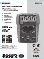
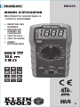
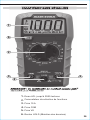
INSTRUCTION MANUAL
ENGLISH
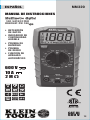
600V
10A
2M
Ω
• DATA HOLD
• AUDIBLE
CONTINUITY
• BATTERY TEST
• DIODE TEST
• AUTO
POWER-OFF
FRANÇAIS p. 25
ESPAÑOL pág. 13
Manual-Ranging
Digital Multimeter
Digital Multimeter
5001748
MM320
CAT III
600V

2
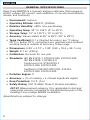
GENERAL SPECIFICATIONS
Klein Tools MM320 is a manual ranging multimeter that measures
AC/DC voltage, DC current, and resistance. It can also test batteries,
diodes, and continuity.
• Environment: Indoors
• Operating Altitude: 6562 ft. (2000m)
• Relative Humidity: <80% non-condensing
• Operating Temp: 32° to 104°F (0° to 40°C)
• Storage Temp: 14° to 140°F (-10° to 60°C)
• Accuracy: Values stated at 65° to 83°F (18° to 28°C)
• Temp Coef cient: 0.1 x (Quoted Accuracy) per °C above
28°C or below 18°C, corrections are required when ambient
working temp is outside of Accuracy Temp range
• Dimensions: 6.39" × 3.12" × 1.80" (162 × 79.4 × 45.7 mm)
• Weight: 8.1 oz. (230 g)
• Calibration: Accurate for one year
• Standards: IEC EN 61010-1, 61010-2-030, 61010-2-033.
IEC EN 61326-1, 61326-2-2.
Conforms to UL STD.61010-1,
61010-2-030, 61010-2-033.
Certified to CSA STD.C22.2 NO. 61010-1,
61010-2-030, 61010-2-033.
• Pollution degree: 2
• Accuracy: ± (% of reading + # of least significant digits)
• Drop Protection: 3.3 ft. (1m)
• Safety Rating: CAT III 600V, Class 2, Double insulation
CAT III: Measurement category III is applicable to test and
measuring circuits connected to the distribution part of the
building’s low-voltage MAINS installation.
Specifications subject to change.
ENGLISH

3
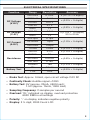
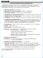
ELECTRICAL SPECIFICATIONS
Function Range Resolution Accuracy
DC Voltage
(V DC)
200.0mV 0.1mV ± (0.7% + 5 digits)
2000mV 1mV
±(0.5% + 5 digits)
20.00V 0.01V
200.0V 0.1V
±(0.8% + 5 digits)
600V 1V
AC Voltage
(V AC)
200.0V 0.1V
±(1.2% + 10 digits)
50 to 60Hz
600V 1V
DC Current
(A DC)
200.0μA 0.1μA
±(1.0% + 5 digits)20.00mA 10μA
200.0mA 100μA
10.00A 10mA ±(2.0% + 5 digits)
Resistance
200.0Ω 0.1Ω ±(1.0% + 5 digits)
2000Ω 1Ω
±(0.8% + 5 digits)20.00kΩ 0.01kΩ
200.0kΩ 0.1kΩ
2000kΩ 1kΩ ±(1.2% + 5 digits)
Battery Test
9V 10mV
±(0.5% + 5 digits)
1.5V 1mV
• Diode Test: Approx. 0.6mA, open circuit voltage 2.0V DC
• Continuity Check: Audible signal <100Ω
• Battery Test: 9V (approx. 20mA, 450Ω load);
1.5V (approx. 15mA, 100Ω load)
• Sampling Frequency: 2 samples per second
• Overload: "OL" indicated on display, overload protection
600V RMS in all settings
• Polarity: "-" on display indicates negative polarity
• Display: 3 ½ digit, 2000 Count LCD

4
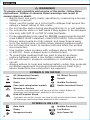
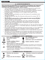
WARNINGS
To ensure safe operation and service of the meter, follow these
instructions. Failure to observe these warnings can result in
severe injury or death.
• Before each use verify meter operation by measuring a known
voltage or current.
• Never use the meter on a circuit with voltages that exceed the
category based rating of this meter.
• Do not use the meter during electrical storms or in wet weather.
• Do not use the meter or test leads if they appear to be damaged.
• Use only with CAT III or CAT IV rated test leads.
• Probe assemblies to be used for MAINS measurements should
meet EN61010-031 standard, rated CATIII 600V, 10A or better.
• Ensure meter leads are fully seated, and keep fingers away
from the metal probe contacts when making measurements.
• Do not open the meter to replace batteries while the probes
are connected.
• Use caution when working with voltages above 25V AC RMS
or 60V DC. Such voltages pose a shock hazard.
• To avoid false readings that can lead to electrical shock,
replace batteries when a low battery indicator appears.
• Do not attempt to measure resistance or continuity on a live
circuit.
• Always adhere to local and national safety codes. Use personal
protective equipment to prevent shock and arc blast injury
where hazardous live conductors are exposed.
SYMBOLS ON METER
AC (Alternating Current) DC (Direct Current)
Resistance (in Ohms) Ground
Diode Audible Continuity
Fuse (with rating below symbol) Double Insulated Class II
Warning or Caution
To ensure safe operation and service of this meter, follow all
warnings and instructions detailed in this manual.
Risk of Electrical Shock
Improper use of this meter can lead to risk of electrical shock. Follow
all warnings and instructions detailed in this manual.
SYMBOLS ON LCD
H
Data Hold Audible Continuity
Diode Low Battery
Dangerous levels Auto Power-Off
ENGLISH

5
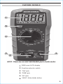
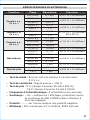
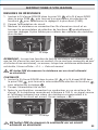
FEATURE DETAILS
1
6
2
3 5
4
1.
2000 count LCD display
2.
Function selector switch
3.
"10A" jack
4.
"COM" jack
5.
"VΩ" jack
6.
"HOLD" (Data Hold) button
NOTE: There are no user-serviceable parts inside meter.

6
ENGLISH
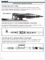
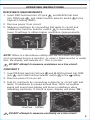
OPERATING INSTRUCTIONS
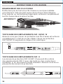
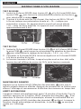
CONNECTING TEST LEADS
Do not test if leads are improperly seated. Results could cause
intermittent display readings. To ensure proper connection, firmly
press leads into the input jack completely.
TESTING IN CAT III / CAT IV MEASUREMENT LOCATIONS
Ensure the test lead shield is pressed firmly in place. Failure to use
the CAT III / CAT IV shield increases arc-flash risk.
TESTING IN CAT II MEASUREMENT LOCATIONS
CAT III / CAT IV shields may be removed for CAT II locations. This
will allow testing on recessed conductors such as standard wall
outlets. Take care not to lose the shields.
5/32"
(4 mm)
.7" (18 mm)
INCORRECT
CORRECT

7
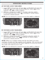
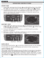
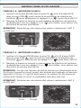
DC VOLTAGE (LESS THAN 600V)
1. Insert RED test lead into VΩ jack
5
, and BLACK test lead into
COM jack
4
, and rotate function selector switch
2
to the
highest V DC (
) setting (600V).
2. Measure voltage and rotate the function selector switch to
successively lower V DC (
) settings to obtain higher
resolution measurements.
NOTE: When in a voltage setting and the test leads are open,
readings of order mV may appear on the display. This is noise and
is normal. By touching the test leads together to close the circuit
the meter will measure zero volts.
NOTE: Do not attempt to measure more than 600V or 200mA.
OPERATING INSTRUCTIONS
AC VOLTAGE (LESS THAN 600V)
1. Insert RED test lead into VΩ jack
5
, and BLACK test lead into
COM jack
4
, and rotate function selector switch
2
to the
highest V AC (
) setting (600V).
2. Measure voltage and rotate the function selector switch
to successively lower V AC (
) settings to obtain higher
resolution measurements.
NOTE: Do not attempt to measure more than 600V or 200mA.
Red leadBlack lead
Red leadBlack lead

8
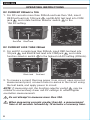
OPERATING INSTRUCTIONS
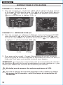
DC CURRENT 200mA to 10A
1. For DC currents more than 200mA and less than 10A, insert
RED test lead into 10A jack
3
, and BLACK test lead into COM
jack
4
, and rotate function selector switch
2
to the
10A DC setting.
DC CURRENT LESS THAN 200mA
2. For mA DC currents less than 200mA, insert RED test lead into
VΩ jack
5
, and BLACK test lead into COM jack
4
, and rotate
function selector switch
2
to the highest mA DC setting (200mA).
3. To measure current: Remove power from circuit, open circuit at
measurement point, connect meter in-series in the circuit using
the test leads, and apply power to circuit.
NOTE: If measuring mA, the function selector switch
2
may be
rotated to successively lower mA DC settings to obtain higher
resolution measurements.
ENGLISH
Do not attempt to measure more than 10A.
When measuring currents greater than 6A, a measurement
time of 30 seconds followed by 10 minutes of recovery time.
Red lead Black lead
Red leadBlack lead

9
OPERATING INSTRUCTIONS
RESISTANCE MEASUREMENTS
1. Insert RED test lead into VΩ jack
5
, and BLACK test lead
into COM jack
4
,
and rotate function selector switch
2
to the
highest Ω setting (2MΩ).
2. Remove power from circuit.
3. Measure resistance by connecting test leads to circuit and
rotating the function selector switch
2
to successively
lower Ω settings to obtain higher resolution measurements.
NOTE: When in a Resistance setting and the test leads are open
(not connected across a resistor), or when a failed resistor is under
test, the display will indicate O.L. This is normal.
DO NOT attempt to measure resistance on a live circuit.
CONTINUITY
1. Insert RED test lead into VΩ jack
5
and BLACK test lead into COM
jack
4
, and rotate function selector switch
2
to the setting.
2. Remove power from circuit.
3. Test for continuity by connecting conductor or circuit with test
leads. If resistance is measured less than 100Ω, an audible
signal will sound and display will show a resistance value
indicating continuity. If circuit is open, display will show "OL".
DO NOT attempt to measure continuity on a live circuit.
Red leadBlack lead
Red leadBlack lead

10
ENGLISH
OPERATING INSTRUCTIONS
DIODE TEST
1. Insert RED test lead into VΩ jack
5
and BLACK test lead into COM
jack
4
, and rotate function selector switch
2
to the setting.
2. Touch test leads to diode. A reading of 200-700mV on display
indicates forward bias, OL indicates reverse bias. An open
device will show OL in both polarities. A shorted device will
show approximately 0mV.
BATTERY TEST
1. Insert RED test lead into VΩ jack
5
and BLACK test lead into
COM jack
4
, and rotate function selector switch
2
to the 1.5V
or 9V battery test setting.
2. Connect BLACK lead to negative, and RED lead to positive
terminal of battery.
3. Measure voltage on display, batteries in good condition should
be within approx. 10% of rated voltage.
DATA HOLD
Press Data Hold button
6
t
o hold the measurement on the display.
Press again to release the display and return to live measuring.
AUTO POWER-OFF
The meter will automatically power off after 15 minutes of inactivity.
Reactivate meter by pressing the Data Hold button
6
button. To
deactivate the automatic power off feature, power the meter on with
the Data Hold button
6
button depressed. When Auto Power-Off is
deactivated, the symbol will not be visible in the display
Red leadBlack lead
Red leadBlack lead

11
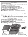
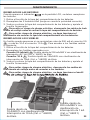
MAINTENANCE
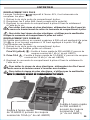
BATTERY REPLACEMENT
When indicator is displayed on LCD, batteries must be replaced.
1. Remove screw from battery door.
2. Replace 2 x AAA batteries (note proper polarity).
3. Replace battery door and fasten securely with screw.
FUSE REPLACEMENT
A fuse may blow if more than 200mA is applied to the
VΩ
jack
5
,
or more than 10A is applied to the 10A jack
3
. To access fuses:
1. Remove screw from battery door.
2. Replace blown fuse(s) with:
VΩ (μA/mA) jack
5
: 200mA/600V fast-blow, interrupting rating 1kA
(Klein Cat. No. 69031)
10A jack
3
: 10A/600V fast-blow, interrupting rating 10kA
(Klein Cat. No. 69032)
3. Replace battery door and fasten securely with screw.
T
o avoid risk of electric shock, disconnect leads from any
voltage source before removing battery door.
To avoid risk of electric shock, do not operate meter while
battery door is removed.
To avoid risk of electric shock, disconnect leads from any
voltage source before accessing fuses.
To avoid risk of electric shock, do not operate meter while
back housing is removed.
10A/600V
fast-blow fuse
, interrupting rating 10kA
(Klein Cat. No. 69032)
200mA/600V
fast-blow fuse
,
interrupting rating 1kA
(Klein Cat. No. 69031)

ENGLISH
CLEANING
Be sure meter is turned off and wipe with a clean, dry lint-free
cloth.
Do not use abrasive cleaners or solvents.
STORAGE
Remove the batteries when meter is not in use for a prolonged
period of time. Do not expose to high temperatures or
humidity. After a period of storage in extreme conditions
exceeding the limits mentioned in the General Specifications
section, allow the meter to return to normal operating
conditions before using.
WARRANTY
www.kleintools.com/warranty
DISPOSAL / RECYCLE
Do not place equipment and its accessories in the trash.
Items must be properly disposed of in accordance with local
regulations. Please see www.epa.gov or www.erecycle.org
for additional information.
CUSTOMER SERVICE
KLEIN TOOLS, INC.
450 Bond Street
Lincolnshire, IL 60069
1-800-553-4676
www.kleintools.com
1390422 Rev 06/20 A

13
MANUAL DE INSTRUCCIONES
ESPAÑOL
600 V
10 A
2 M
Ω
• RETENCIÓN
DEDATOS
• INDICADOR DE
CONTINUIDAD
AUDIBLE
• PRUEBA DE
BATERÍAS
• PRUEBA
DE DIODO
• FUNCIÓN DE
APAGADO
AUTOMÁTICO
Multímetro digital
con selección
manual de rango
5001748
MM320
CAT III
600 V
con selección
manual de rango

14
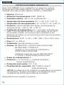
ESPECIFICACIONES GENERALES
Klein Tools MM320 es un multímetro con selección manual
de rango que mide voltaje CA/CD, corriente CD y resistencia.
Tambiénsirve para probar baterías, diodos y continuidad.
• Entorno: interiores
• Altitud de funcionamiento: 6562' (2000m)
• Humedad relativa: <80%, sin condensación
• Temperatura de funcionamiento: 32° a 104°F (0° a 40°C)
• Temperatura de almacenamiento: 14° a 140°F (-10° a 60°C)
• Precisión: valores establecidos según una temperatura
ambiente de 65° a 83°F (18° a 28°C)
• Coe ciente de temperatura: 0,1 × (precisión indicada) por
cada °C por encima de los 28°C o por debajo de los 18°C,
esnecesario realizar correcciones si la temperatura del
ambiente de trabajo se encuentra fuera del rango de precisión
de temperatura
• Dimensiones: 6,39"×3,12"×1,80"(162×79,4×45,7mm)
• Peso: 8,1oz(230g)
• Calibración: precisa durante un año
• Normas: IECEN61010-1, 61010-2-030, 61010-2-033.
IECEN61326-1, 61326-2-2.
Cumple con las normas UL STD.61010-1,
61010-2-030 y 61010-033.
Certificado según las normas CSA STD.C22.2
n.º 61010-1, 61010-2-030 y 61010-2-033.
• Grado de contaminación: 2
• Precisión: ± (% de lectura + cantidad de dígitos
menossignificativos)
• Protección ante caídas: 3,3'(1m)
• Clasi cación de seguridad: CATIII 600V, clase2,
dobleaislamiento
CATIII: la categoría III de medición es aplicable a los circuitos
de medición y prueba conectados a la distribución de la
instalación de red de bajo voltaje de un edificio.
Especificaciones sujetas a cambios.
ESPAÑOL

15
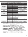
ESPECIFICACIONES ELÉCTRICAS
Función Rango Resolución Precisión
Voltaje CD
(V CD)
200,0mV 0,1mV ±(0,7% + 5dígitos)
2000mV 1mV
± (0,5% + 5dígitos)
20,00V 0,01V
200,0V 0,1V
± (0,8% + 5dígitos)
600V 1V
Voltaje CA
(V CA)
200,0V 0,1V
± (1,2% + 10dígitos)
50 a 60Hz
600V 1V
Corriente CD
(A CD)
200,0μA 0,1μA
± (1,0% + 5dígitos)20,00mA 10μA
200,0mA 100μA
10,00A 10mA ± (2,0% + 5dígitos)
Resistencia
200,0Ω 0,1Ω ± (1,0% + 5dígitos)
2000Ω 1Ω
± (0,8% + 5dígitos)20,00kΩ 0,01kΩ
200,0kΩ 0,1kΩ
2000kΩ 1kΩ ± (1,2% + 5dígitos)
Prueba de
baterías
9V 10mV
± (0,5% + 5dígitos)
1,5V 1mV
• Prueba de diodo: 0,6mA aprox., 2,0VCD de voltaje
decircuito abierto
• Veri cación de continuidad: señal audible <100Ω
• Prueba de batería: 9V (aprox. 20mA, carga de 450Ω);
1,5V (aprox. 15mA, carga de 100Ω)
• Frecuencia de muestreo: 2 muestras por segundo
• Sobrecarga: se indica “OL” (SOBRECARGA) en pantalla,
protección contrasobrecarga de 600VRMS en
todaslasposiciones
• Polaridad: “-” en pantalla indica polaridad negativa
• Pantalla: LCD de 3 ½ dígitos con recuento de 2000

16
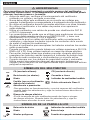
ADVERTENCIAS
Para garantizar un funcionamiento y servicio seguros del multímetro,
siga estas instrucciones. El incumplimiento de estasadvertencias puede
provocar lesiones graves o la muerte.
• Antes de cada uso, verifique el funcionamiento del multímetro
midiendo un voltaje o corriente conocidos.
• Nunca debe utilizar este multímetro en un circuito con voltajes que
excedan la clasificación correspondiente a la categoría de este multímetro.
• No utilice el multímetro durante tormentas eléctricas o en clima húmedo.
• No utilice el multímetro o los cables de prueba si en apariencia
estándañados.
• Utilice el multímetro con cables de prueba con clasificación CATIII
oCAT IV únicamente.
• Los ensamblajes de sonda que se utilicen para mediciones de redes
eléctricas debe cumplir con la norma EN61010-031, y tener una
clasificación CATIII 600V, 10A o superior.
• Asegúrese de que los cables del multímetro estén correctamente
colocados y mantenga los dedos lejos de los contactos de la sonda
demetal al realizar las mediciones.
• No abra el multímetro para reemplazar las baterías mientras las sondas
están conectadas.
• Proceda con precaución cuando trabaje con voltajes superiores a 25VCA
RMS o 60VCD. Esos voltajes implican un riesgo de choque eléctrico.
• Para evitar lecturas falsas que puedan provocar choques eléctricos,
reemplace las baterías cuando aparezca el indicador de batería baja.
• No intente medir resistencia o continuidad en un circuito activo.
• Cumpla siempre con los códigos de seguridad locales y nacionales.
Utilice equipo de protección personal para prevenir lesiones por
choque y arco eléctrico en los lugares donde haya conductores activos
peligrosos expuestos.
SÍMBOLOS DEL MULTÍMETRO
CA (corriente alterna) CD (corriente directa)
Resistencia (en ohmios) Conexión a tierra
Diodo
Indicador de continuidad audible
Fusible (con su clasi cación
debajo del símbolo)
Doble aislamiento Clase II
Advertencia o precaución
Para garantizar un funcionamiento y servicio seguros del multímetro,
respete todas las advertencias y siga las instrucciones descritas en
este manual.
Riesgo de choque eléctrico
El uso incorrecto de este multímetro puede dar lugar a riesgos
de choque eléctrico. Respete todas las advertencias y siga las
instrucciones descritas en este manual.
SÍMBOLOS DE LA PANTALLA LCD
H
Retención de datos Indicador de continuidad audible
Diodo Batería baja
Niveles peligrosos Función de apagado automático
ESPAÑOL

17
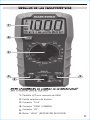
DETALLES DE LAS CARACTERÍSTICAS
1.
Pantalla LCD con recuento de 2000
2.
Perilla selectora de función
3.
Conector “10A”
4.
Conector “COM” (COMÚN)
5.
Conector “VΩ”
6.
Botón “HOLD” (RETENCIÓN DE DATOS)
NOTA: el multímetro no contiene en su interior piezas
que el usuario pueda reparar.
DETALLES DE LAS CARACTERÍSTICAS
NOTA:
el multímetro no contiene en su interior piezas
que el usuario pueda reparar.
1
6
2
3 5
4

18
ESPAÑOL
INSTRUCCIONES DE FUNCIONAMIENTO
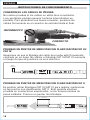
CONEXIÓN DE LOS CABLES DE PRUEBA
No realice pruebas si los cables no están bien conectados.
Losresultados podrían generar lecturas intermitentes en
pantalla. Paragarantizar una buena conexión, presione los
cablesfirmemente en el conector de entrada hasta el final.
PRUEBAS EN PUNTOS DE MEDICIÓN CON CLASIFICACIÓN CATIII/
CAT IV
Asegúrese de que el blindaje del cable de prueba esté firmemente
colocado en su lugar. No utilizar el blindaje CAT III/CAT IV aumenta
el riesgo de que se produzca un arco eléctrico.
PRUEBAS EN PUNTOS DE MEDICIÓN CON CLASIFICACIÓN CATII
Es posible retirar blindajes CATIII/CATIV para realizar mediciones
en los puntos con clasificación CATII. Esto permite efectuar
pruebas en conductores empotrados, como tomacorrientes de
pared estándar. Procure no perder los blindajes.
5/32"
(4 mm)
.7" (18 mm)
INCORRECTO
CORRECTO

19
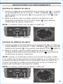
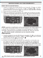
VOLTAJE CD (MENOS DE 600V)
1. Inserte el cable de prueba ROJO en el conector VΩ
5
y el cable de
prueba NEGRO en el conector “COM” (COMÚN)
4
, y gire la perilla
selectora de función
2
a la posición más alta de VCD ( ) (600V).
2. Mida el voltaje y gire la perilla selectora de función a las
subsiguientes posiciones más bajas de VCD (
) para obtener
mediciones de mayor resolución.
NOTA: cuando el multímetro está en la posición de medir voltaje
y los cables de prueba están en circuito abierto, es posible que se
visualicen lecturas del tipo mV en la pantalla. Esto es ruido y es
normal. Al juntar los cables de prueba para cerrar el circuito, la
lectura del multímetro será de cero voltios.
NOTA: no intente medir más de 600V o 200mA.
INSTRUCCIONES DE FUNCIONAMIENTO
VOLTAJE CA (MENOS DE 600V)
1. Inserte el cable de prueba ROJO en el conector VΩ
5
y el cable
de prueba NEGRO en el conector “COM” (COMÚN)
4
, y gire la
perilla selectora de función
2
a la posición de VCA ( ) más
alta (600V).
2. Mida el voltaje y gire la perilla selectora de función a las
siguientes posiciones de VCA más bajas (
) para obtener
mediciones de mayor resolución.
NOTA: no intente medir más de 600V o 200mA.
Cable rojoCable negro
Cable rojoCable negro

20
ESPAÑOL
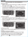
INSTRUCCIONES DE FUNCIONAMIENTO
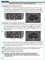
CORRIENTE CD (200mA a 10A)
1. Para medir corrientes CD mayores que 200mA y menores que
10A, inserte el cable de prueba ROJO en el conector 10A
3
y
el cable de prueba NEGRO en el conector “COM” (COMÚN)
4
,
y gire la perilla selectora de función
2
a la posición de 10ACD.
CORRIENTE CD (MENOS DE 200mA)
2. Para medir corrientes CD en mA menores que 200mA, inserte
el cable de prueba ROJO en el conector VΩ
5
y el cable de
prueba NEGRO en el conector “COM” (COMÚN)
4
, y gire la
perilla selectora de función
2
a la posición más alta de CD en
mA (200mA).
3.
4. Para medir la corriente realice lo siguiente: desconecte la energía
del circuito, abra el circuito en el punto de medición, conecte el
multímetro en serie en el circuito utilizando los cables de prueba
y suministre energía al circuito.
NOTA: al medir mA, la perilla selectora de función
2
puede girarse
a las subsiguientes posiciones más bajas de mA para obtener
mediciones de mayor resolución.
No intente medir más de 10A.
Cuando realice mediciones de corriente de valores
mayores que 6A, utilizar un tiempo de medición de
30segundos seguido de otros 10minutos detiempo de
recuperación.
Cable rojo Cable negro
3.
Cable rojoCable negro
La page est en cours de chargement...
La page est en cours de chargement...
La page est en cours de chargement...
La page est en cours de chargement...
La page est en cours de chargement...
La page est en cours de chargement...
La page est en cours de chargement...
La page est en cours de chargement...
La page est en cours de chargement...
La page est en cours de chargement...
La page est en cours de chargement...
La page est en cours de chargement...
La page est en cours de chargement...
La page est en cours de chargement...
La page est en cours de chargement...
La page est en cours de chargement...
-
 1
1
-
 2
2
-
 3
3
-
 4
4
-
 5
5
-
 6
6
-
 7
7
-
 8
8
-
 9
9
-
 10
10
-
 11
11
-
 12
12
-
 13
13
-
 14
14
-
 15
15
-
 16
16
-
 17
17
-
 18
18
-
 19
19
-
 20
20
-
 21
21
-
 22
22
-
 23
23
-
 24
24
-
 25
25
-
 26
26
-
 27
27
-
 28
28
-
 29
29
-
 30
30
-
 31
31
-
 32
32
-
 33
33
-
 34
34
-
 35
35
-
 36
36


Klein Tools 69355 Mode d'emploi
- Catégorie
- Mesure, test
- Taper
- Mode d'emploi
- Ce manuel convient également à
dans d''autres langues
Documents connexes
-
Klein Tools 80067 Manuel utilisateur
-
-
-
-
-
-
Klein Tools CL220 Manuel utilisateur
-
-
Klein Tools MM700 Mode d'emploi
-