Sauder Barrister Lane Hutch 418295 Mode d'emploi
- Taper
- Mode d'emploi

Need help? Visit Sauder.com to view video assembly tips or chat with a live rep.
Prefer the phone? Call 1-800-523-3987.
Share your journey!
sauder.com
NOTE: THIS INSTRUCTION
BOOKLET CONTAINS IMPORTANT
SAFETY INFORMATION.
PLEASE READ AND KEEP FOR
FUTURE REFERENCE.
English pg 1-17
Français pg 18-19
Español pg 20-21
Lot # 366595 11/25/14
Purchased: __________________
Be sure to give us a ring before
making any returns. 1-800-523-3987
Hutch
Barrister Lane Collection | 418295
For things 'n such.

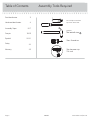
Table of Contents Assembly Tools Required
Part Identifi cation
Hardware Identifi cation
Assembly Steps
Français
Español
Safety
Warranty
No. 2 Phillips Screwdriver
Tip Shown Actual Size
Hammer
Not actual size
3
4
5-17
18-19
20-21
22
23
418295 www.sauder.com/servicesPage 2
Short Screwdriver
Skip the power trip.
This time.

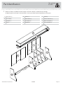
Part Identifi cation
å While not all parts are labeled, some of the parts will have a label or an inked letter on the edge
to help distinguish similar parts from each other. Use this part identifi cation to help identify similar parts.
Now you know
our ABCs.
A RIGHT END (1)
B LEFT END (1)
C UPRIGHT (1)
D TOP (1)
E SHELF (1)
F RIGHT BACK (1)
G LEFT BACK (1)
H DIVIDER (3)
I SKIRT (1)
J FRONT MOLDING (1)
K RIGHT MOLDING (1)
L LEFT MOLDING (1)
418295www.sauder.com/services
Page 3
A
B
C
D
E
F
G
H
I
J
K
L
H
H

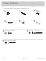
Hardware Identifi cation
å Screws are shown actual size. You may receive extra hardware with your unit.
418295 www.sauder.com/servicesPage 4
BLACK 9/16" LARGE HEAD SCREW - 3
1S
BLACK 1-1/4" FLAT HEAD SCREW - 9
7S
BLACK 1-7/8" FLAT HEAD SCREW - 3
2S
36P
CAM COVER - 10
MOLDING
CONNECTOR - 2
17F
METAL PIN - 11
1R
NAIL - 36
1N
HIDDEN CAM - 12
1F
CAM DOWEL - 12
2F

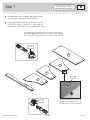
Step 1
Look for this icon. It means a
video assembly tip is available at
www.sauder.com/services/tips
å
Assemble your unit on a carpeted fl oor or on the empty
carton to avoid scratching your unit or the fl oor.
å
Push twelve HIDDEN CAMS (1F) into the ENDS (A and B),
UPRIGHT (C), SHELF (E), and SKIRT (I). Then, insert the
metal end of a CAM DOWEL (2F) into each HIDDEN CAM.
418295www.sauder.com/services
Page 5
A
B
C
E
I
Arrow
1F
2F
(12 used)
Arrow
1F
2F
Do not tighten the HIDDEN CAMS in this step.
Insert the metal end of the CAM
DOWEL into the HIDDEN CAM.
Arrow

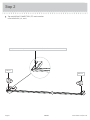
å
Tap two MOLDING CONNECTORS (17F) into the notches
in the MOLDINGS (J, K, and L).
Step 2
418295 www.sauder.com/servicesPage 6
K
J
17F
17F
L
Use your hammer to tap the MOLDING CONNECTOR (17F) into the notches in the MOLDINGS.
Flat end
Flat end

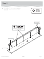
å
Turn the MOLDINGS (J, K, and L) over and fasten them
to the TOP (D). Use nine BLACK 1-1/4" FLAT HEAD
SCREWS (7S).
Step 3
418295www.sauder.com/services
Page 7
D
K
J
L
Surface with holes
Remember:
Righty tighty.
Lefty loosey.
Finished surface
Finished surface
Rounded edge
BLACK 1-1/4" FLAT HEAD SCREW
(9 used in this step)
7S

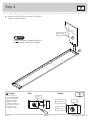
å
Fasten the RIGHT END (A) to the RIGHT MOLDING (K).
Tighten two HIDDEN CAMS.
Step 4
418295 www.sauder.com/servicesPage 8
Start Tighten
Arrow
Minimum
190 degrees
Caution
Risk of damage or
injury. HIDDEN CAMS
must be completely
tightened. HIDDEN
CAMS that are not
completely tightened
may loosen, and parts
may separate. To
completely tighten:
Arrow
Maximum
210 degrees
A
K
J
Curved edge
Surface with
HIDDEN CAMS
Do not stand the unit upright without the
BACK fastened. The unit may collapse.
Caution

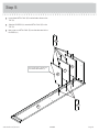
å
Insert three METAL PINS (1R) into the holes shown in the
TOP (D).
å
Slide the DIVIDERS (H) onto the METAL PINS (1R) in the
TOP (D).
å
Now, insert six METAL PINS (1R) into the other end of the
DIVIDERS (H).
Step 5
418295www.sauder.com/services
Page 9
D
H
H
H
J
1R
1R
All curved edges should face
the FRONT MOLDING (J).

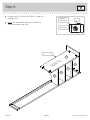
å
Fasten the SHELF (E) to the RIGHT END (A). Tighten two
HIDDEN CAMS.
å
NOTE: Be sure the METAL PINS in the DIVIDERS (H)
insert into the holes in the SHELF.
Step 6
418295 www.sauder.com/servicesPage 10
A
H
H
H
E
Surface with
HIDDEN CAMS
Arrow
Minimum
190 degrees
Maximum
210 degrees
Finished edge

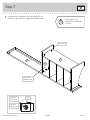
å
Using your short screwdriver, fasten the UPRIGHT (C) to
the TOP (D) and SHELF (E). Tighten four HIDDEN CAMS.
Step 7
418295www.sauder.com/services
Page 11
Don't worry. It isn't
Rome. This can be built
in a day.
E
D
C
Curved edge
Arrow
Minimum
190 degrees
Maximum
210 degrees
Surface with
HIDDEN CAMS

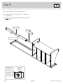
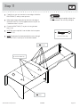
å
Insert a METAL PIN (1R) into the UPRIGHT (C).
å
Fasten the SKIRT (I) to the UPRIGHT (C). Tighten one
HIDDEN CAM.
å
NOTE: Be sure the METAL PIN in the UPRIGHT inserts
into the SKIRT.
Step 8
418295 www.sauder.com/servicesPage 12
Arrow
Minimum
190 degrees
Maximum
210 degrees
C
1R
I
Curved edge
Surface with holes

å
Insert a METAL PIN (1R) into the LEFT END (B).
å
Fasten the LEFT END (B) to the LEFT MOLDING (L) and
SKIRT (I). Tighten three HIDDEN CAMS.
å
NOTE: Be sure the METAL PIN in the LEFT END inserts into
the SKIRT.
Step 9
418295www.sauder.com/services
Page 13
I
B
1R
Arrow
Minimum
190 degrees
Maximum
210 degrees
Curved edge
L
Surface with
HIDDEN CAMS

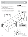
Step 10
418295 www.sauder.com/servicesPage 14
å
Push a CAM COVER (36P) onto each visible HIDDEN CAM in
the ENDS (A and B), UPRIGHT (C), and SHELF (E).
36P
(10 used)
To cover HIDDEN CAMS
B
C
A
E
Hey! It's starting to look
like something!

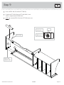
å
Carefully turn your unit over onto its front edges. Unfold the
RIGHT BACK (F) and lay it over your unit.
å
Make equal margins along the top and outer side edge of
the RIGHT BACK (F). Push on opposite corners of your unit
if needed to make it “square”.
å
Fasten the RIGHT BACK (F) to your unit using fourteen
NAILS (1N).
å
NOTE: Be sure to tap NAILS into the holes that line up over
the SHELF (E).
å
NOTE: Perforations have been provided for access through
the RIGHT BACK. Carefully cut out the holes needed.
Step 11
418295www.sauder.com/services
Page 15
Do not stand the unit upright without the
BACK fastened. The unit may collapse.
Caution
NAIL
(14 used in this step)
1N
F
These holes must line
up over the SHELF (E).
Do not tap a NAIL
into this hole.
Do not tap NAILS
into these holes.

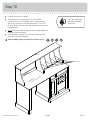
Step 12
418295 www.sauder.com/servicesPage 16
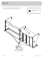
å
Unfold the LEFT BACK (G) and lay it over your unit.
å
Make equal margins along the top and outer edge of the
LEFT BACK (G). Push on opposite corners of your unit if
needed to make it “square”.
å
NOTE: The LEFT BACK (G) will overlap the RIGHT BACK (F).
Follow the enlarged diagram.
å
Fasten the LEFT BACK (G) to your unit using three BLACK
9/16" LARGE HEAD SCREWS (1S) into the holes shown in
the LEFT BACK. Use fi fteen NAILS (1N) into the top and
both side edges.
Do not stand the unit upright without the
BACK fastened. The unit may collapse.
Caution
NAIL
(15 used in this step)
1N
F
G
G
F
The LEFT BACK (G) will
overlap the RIGHT BACK (F).
BLACK 9/16" LARGE HEAD SCREW
(3 used in this step)
1S
Do not tap NAILS into
the bottom row of holes.
Notch

å
Carefully stand your unit upright.
å
The instructions for fastening your unit to the 418294
Computer Desk is in the Computer Desk assembly manual.
You will use seven NAILS (1N) and three BLACK 1-7/8" FLAT
HEAD SCREWS (2S) from your Hutch hardware to fasten to the
Computer Desk.
å
NOTE: Please read the back pages of the instruction booklet for
important safety information.
å
This completes assembly. Clean with your favorite furniture
polish or a damp cloth. Wipe dry.
Step 13
418295www.sauder.com/services
Page 17
And to celebrate, why not share your success story?
30 lbs.
20 lbs. total
418294
Computer Desk
Pro Tip: Lift with your
legs. And, you know,
your arms.

A l’usage exclusif du
Canada Noter la date
d’achat de cet élément
et conserver le livret
pour future référence.
Pour contacter Sauder
en ce qui concerne cet
élément, faire référence
au numéro de lot et
numéro de modèle en
appelant notre numéro
sans frais.
Lot nº : ____________
Date de
l’achat: ____________
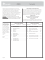
LISTE DE PIÈCES
REFERENCE DESCRIPTION QUANTITÉ
LISTE DE PIÈCES
REFERENCE DESCRIPTION QUANTITÉ
NOUS SOMMES LA POUR VOUS AIDER!
Nous faisons de notre mieux pour nous assurer que votre meuble
arrive dans d’excellentes conditions. Nos représentants du service
Clientèle sont aimables et prêts à vous aider au cas où une pièce
aurait été endommagée ou manquerait (ou si vous aviez besoin
d’aide pour l’assemblage). NE RAMENEZ PAS LE MEUBLE AU
MAGASIN. Au Canada, composez ce numéro d’appel gratuit:
1-800-523-3987
Du lundi au vendredi, de 9 heures du matin à
5:30 heures du soir (horaire Côte Est)
(sauf jours fériés)
Si une pièce a besoin d’être remplacée, la pièce de remplacement
sera envoyée dans les 48 heures. (Sauf week-ends et jours fériés)
Utilisez les instructions d’assemblage en français avec les
schémas étape par étape du manuel d’instruction en anglais.
Chaque étape en français correspond à la même étape
en anglais. La pièce devant être attachée à l’élément est
représentée en gris sur les schémas de chaque étape pour plus
de précision. Comparer la “Liste de pièces” ci-dessous avec
la “PART IDENTIFICATION” du manuel en anglais pour vous
familiariser avec les pièces avant l’assemblage.
REMARQUE : CE MANUEL D’INSTRUCTIONS CONTIENT
D’IMPORTANTES INFORMATIONS RELATIVES À LA SÉCURITÉ.
À LIRE ET CONSERVER POUR TOUTE RÉFÉRENCE FUTURE.
1F EXCENTRIQUE ESCAMOTABLE ...................12
2F CHEVILLE D'EXCENTRIQUE ............................12
17F CONNECTEUR DE MOULURE..........................2
1N CLOU ................................................................................36
36P COUVERCLE D'EXCENTRIQUE ....................10
1R GOUPILLE EN MÉTAL ............................................11
1S VIS TÊTE LARGE 14 mm NOIRE .....................3
2S VIS TÊTE PLATE 48 mm NOIRE .....................3
7S VIS TÊTE PLATE 32 mm NOIRE .....................9
A EXTRÉMITÉ DROITE ..................................................1
B EXTRÉMITÉ GAUCHE ...............................................1
C MONTANT..........................................................................1
D DESSUS ...............................................................................1
E TABLETTE ..........................................................................1
F ARRIÈRE DROIT.............................................................1
G ARRIÈRE GAUCHE ......................................................1
H SÉPARATEUR .................................................................3
I PLINTHE ..............................................................................1
J MOULURE AVANT .......................................................1
K MOULURE DROITE .....................................................1
L MOULURE GAUCHE .................................................1
Surmeuble418295
418295 www.sauder.com/servicesPage 18

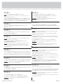
ÉTAPE 10
Enfoncer un COUVERCLE D'EXCENTRIQUE (36P) sur chaque EXCENTRIQUE
ESCAMOTABLE dans les EXTRÉMITÉS (A et B), le MONTANT (C) et la TABLETTE (E).
ÉTAPE 9
Insérer une GOUPILLE EN MÉTAL (1R) dans l'EXTRÉMITÉ GAUCHE (B).
Fixer l'EXTRÉMITÉ GAUCHE (B) à la MOULURE GAUCHE (L) et PLINTHE (I).
Serrer trois EXCENTRIQUES ESCAMOTABLES.
REMARQUE : S'assurer de bien insérer la GOUPILLE EN MÉTAL située sur
l'EXTRÉMITÉ GAUCHE dans la PLINTHE.
ÉTAPE 5
Insérer trois GOUPILLES EN MÉTAL (1R) dans les trous indiqués dans le DESSUS (D).
Insérer les SÉPARATEURS (H) sur les GOUPILLES EN MÉTAL (1R) situées dans le DESSUS (D).
Maintenant, insérer six GOUPILLES EN MÉTAL (1R) dans l'autre extrémité des SÉPARATEURS (H).
ÉTAPE 4
Attention: Ne pas relever l'élément dans sa position verticale avant d'avoir fi xé
l’ARRIÈRE. L'élément risque de s'e ondrer.
Fixer l’EXTRÉMITÉ DROITE (A) à la MOULURE DROITE (K). Serrer deux
EXCENTRIQUES ESCAMOTABLES.
Attention: Risque des dégâts ou blessures. Les Excentriques Escamotables doivent être
serrés à bloc. Les Excentriques Escamotables que ne sont pas serrées à bloc peuvent
desserrer et les pièces peuvent séparer. Pour serrer à bloc, faire tourner l'excentrique
escamotable de 210 degrés.
ÉTAPE 3
Retourner les MOULURES (J, K et L) et les fi xer sur le DESSUS (D). Utiliser neuf
VIS TÊTE PLATE 32 mm NOIRES (7S).
ÉTAPE 2
Enfoncer deux CONNECTEURS DE MOULURE (17F) dans les crans des
MOULURES (J, K et L).
ÉTAPE 1
Ne pas serrer les EXCENTRIQUES ESCAMOTABLES dans cette étape.
Assembler l'élément sur un sol à moquette ou sur le carton vide pour éviter
d'endommager l'élément ou le sol.
Enfoncer douze EXCENTRIQUES ESCAMOTABLES (1F) dans les EXTRÉMITÉS (A et B), le
MONTANT (C), la TABLETTE (E) et la PLINTHE (I). Ensuite, insérer l'extrémité en métal de la
CHEVILLE D'EXCENTRIQUE (2F) dans chaque EXCENTRIQUE ESCAMOTABLE.
ÉTAPE 11
Attention: Ne pas relever l'élément dans sa position verticale avant d'avoir fi xé
l’ARRIÈRE. L'élément risque de s'e ondrer.
Avec précaution, retourner l'élément sur ses chants avant. Déplier l'ARRIÈRE
DROIT (F) et le placer sur l'élément.
Veiller à avoir des marges égales le long du chant supérieur et latéral extérieur de
l'ARRIÈRE DROIT (F). Si besoin est, enfoncer sur les coins opposés de l'élément
pour s'assurer d'être « d'équerre ».
Fixer l'ARRIÈRE DROIT (F) à l'élément à l'aide des quatorze CLOUS (1N).
REMARQUE : S'assurer de bien enfoncer les CLOUS dans les trous qui sont
alignés au-dessus la TABLETTE (E).
REMARQUE : Des lignes perforées ont été prévues pour accéder facilement à
l'ARRIÈRE DROIT. Découper avec précaution les trous nécessaires.
418295www.sauder.com/services
Page 19
ÉTAPE 6
Fixer la TABLETTE (E) à l'EXTRÉMITÉ DROITE (A). Serrer deux EXCENTRIQUES ESCAMOTABLES.
REMARQUE : S'assurer de bien insérer les GOUPILLES EN MÉTAL situées sur les
SÉPARATEURS (H) dans les trous dans la TABLETTE.
ÉTAPE 12
Attention: Ne pas relever l'élément dans sa position verticale avant d'avoir fi xé
l’ARRIÈRE. L'élément risque de s'e ondrer.
Déplier l'ARRIÈRE GAUCHE (G) et le placer sur l'élément.
Veiller à avoir des marges égales le long des chants supérieur et extérieur de
l'ARRIÈRE GAUCHE (G). Si besoin est, enfoncer sur les coins opposés de l'élément
pour s'assurer d'être « d'équerre ».
REMARQUE : L'ARRIÈRE GAUCHE (G) va chevaucher l'ARRIÈRE DROIT (F). Suivre
les indications du schéma agrandi.
Fixer l'ARRIÈRE GAUCHE (G) à l'élément à l'aide de trois VIS TÊTE LARGE
14 mm NOIRES (1S) dans les trous indiqués dans l'ARRIÈRE GAUCHE. Utiliser
quinze CLOUS (1N) dans les chants supérieur et latéraux.
ÉTAPE 13
Relever, avec précaution, l'élément dans sa position verticale.
Les instructions pour fi xer l'élément au Bureau d'ordinateur 418294 sont incluses dans
le manuel du bureau d'ordinateur. Utiliser sept CLOUS (1N) et trois VIS TÊTE PLATE
48 mm NOIRES (2S) de visserie du Surmeuble pour fi xer au Bureau d'ordinateur.
REMARQUE : Prière de lire les informations importantes sur la sécurité fi gurant sur
les pages arrière du manuel d’instructions.
Ceci complète l'assemblage. Nettoyer à l’aide d’une encaustique pour meubles ou
d’un chi on humide. Essuyer.
ÉTAPE 7
Fixer le MONTANT (C) au DESSUS (D) et à la TABLETTE (E) avec le tournevis court. Serrer
quatre EXCENTRIQUES ESCAMOTABLES.
ÉTAPE 8
Insérer une GOUPILLE EN MÉTAL (1R) dans le MONTANT (C).
Fixer la PLINTHE (I) au MONTANT (C). Serrer un EXCENTRIQUE ESCAMOTABLE.
REMARQUE : S'assurer de bien insérer la GOUPILLE EN MÉTAL située sur le
MONTANT dans la PLINTHE.

A l’usage exclusif du
Canada Noter la date
d’achat de cet élément
et conserver le livret
pour future référence.
Pour contacter Sauder
en ce qui concerne cet
élément, faire référence
au numéro de lot et
numéro de modèle en
appelant notre numéro
sans frais.
Lot nº : ____________
Date de
l’achat: ____________
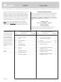
LISTA DE PARTES
ITEM DESCRIPCIÓN CANTIDAD
ESTAMOS AQUI PARA AYUDAR!
Tratamos de asegurar que su mueble llega en condición excelente.
Nuestros representantes de Servicio al Cliente son amables y
listos para ayudarle con servicio rápido y efi ciente si una parte
está defectuosa o ausente (o si necesita ayuda con el ensamblaje).
NO DEVUELVA LA UNIDAD A LA TIENDA. Llame este número sin
cargo:
1-800-523-3987
Lunes a viernes, 9:00 a.m. - 5:30 p.m.
Hora ofi cial del Este
(excepto días festivos)
Si requiere un repuesto de una parte, será enviado dentro de
48 horas (excepto los fi nes de semana y días festivos)
Use estas instrucciones de ensamblaje en español junto con las
fi guras paso-a-paso provistas en el folleto inglés. Cada paso
en español corresponde al mismo paso en inglés. Se destacan
las fi guras de cada paso con una tonalidad oscura para mostrar
precisamente cual parte se debe montar a la unidad. Compare
la “Lista de Part” abajo con la “Part Identifi cation” en el folleto en
inglés para familiarizarse con Las partes de ensamblaje.
NOTA: ESTE FOLLETO DE INSTRUCCIONES CONTIENE
INFORMACIÓN IMPORTANTE SOBRE LA SEGURIDAD. POR
FAVOR LEA Y GUÁRDELO PARA REFERENCIA EN EL FUTURO.
LISTA DE PARTES
ITEM DESCRIPCIÓN CANTIDAD
1F EXCÉNTRICO ESCONDIDO .............................12
2F PASADOR DE EXCÉNTRICO ............................12
17F CONECTOR DE MOLDURA ................................2
1N CLAVO .............................................................................36
36P CUBIERTA DE EXCÉNTRICO...........................10
1R ESPIGA DE METAL ...................................................11
1S TORNILLO NEGRO DE CABEZA
GRANDE de 14 mm ...................................................3
2S TORNILLO NEGRO DE CABEZA
PERDIDA de 48 mm .................................................3
7S TORNILLO NEGRO DE CABEZA
PERDIDA de 32 mm .................................................9
A EXTREMO DERECHO ..........................................................1
B EXTREMO IZQUIERDO .......................................................1
C PARAL ..............................................................................................1
D PANEL SUPERIOR ..................................................................1
E ESTANTE ........................................................................................1
F DORSO DERECHO ................................................................1
G DORSO IZQUIERDO .............................................................1
H DIVISOR .........................................................................................3
I FALDÓN ..........................................................................................1
J MOLDURA DELANTERA ...................................................1
K MOLDURA DERECHA ......................................................... 1
L MOLDURA IZQUIERDA ...................................................... 1
Organizador418295
418295 www.sauder.com/servicesPage 20
La page est en cours de chargement...
La page est en cours de chargement...
La page est en cours de chargement...
La page est en cours de chargement...
-
 1
1
-
 2
2
-
 3
3
-
 4
4
-
 5
5
-
 6
6
-
 7
7
-
 8
8
-
 9
9
-
 10
10
-
 11
11
-
 12
12
-
 13
13
-
 14
14
-
 15
15
-
 16
16
-
 17
17
-
 18
18
-
 19
19
-
 20
20
-
 21
21
-
 22
22
-
 23
23
-
 24
24


Sauder Barrister Lane Hutch 418295 Mode d'emploi
- Taper
- Mode d'emploi
dans d''autres langues
Documents connexes
-
Sauder Storage Organizer 422647 Mode d'emploi
-
-
-
-
-
-
-
-
-