Miller JF923259 Le manuel du propriétaire
- Catégorie
- Système de soudage
- Taper
- Le manuel du propriétaire
Ce manuel convient également à

December
1985
FORM:
OM-1523F
Effective
With
Serial
No.
JF923259
MODEL
SWINGARC
DIGITAL
-2
12
SWINGARC
DIGITAL
-216
OWN
ERS
MANUAL
*
miliEu
MILLER
ELECTRIC
MFG.
CO.
718
S.
BOUNDS
ST,
P.O.
Box
1079
APPLETON,
WI
54912
USA
IMPORTANT
Read
and
understand
the
entire
contents
of
both
this
manual
and
the
power
source
manual
used
with
this
unit,
with
special
emphasis
on
the
safety
material
throughout
both
manuals,
before
installing,
operating,
or
maintaining
this
equipment.
This
unit
and
these
instructions
are
for
use
only
by
persons
trained
and
experienced
in
the
safe
operation
of
welding
equipment.
Do
not
allow
untrained
persons
to
install,
operate,
or
maintain
this
unit.
Contact
your
distributor
if
you
do
not
fully
understand
these
instructions.
PRINTED
IN
U.S.A.

LIMITED
WARRANTY
EFFECTIVE:
FEBRUARY
25.
1985
fr
This
warranty
supersedes
all
previous
MILLER
warranties
and
is
ex
clusive
with
no
other
guarantees
or
warranties
expressed
or
implied.
LIMITED
WARRANTY
-
Subject
to
the
terms
and
condi-
In
the
case
of
Millers
breach
of
warranty
or
any
other
duty
~
tions
hereof,
Miller
Electric
Mfg.
Co.,
Appleton,
Wisconsin
with
respect
to
the
quality
of
any
goods,
the
exclusive
remedies
~
warrants
to
its
Distributor/Dealer
that
all
new
and
unused
therefore
shall
be,
at
Millers
option
(1)
repair
or
(2)
replacement
~
Equipment
furnished
by
Miller
is
free
from
defect
in
workman-
or,
where
authonzed
in
writing
by
Miller
in
appropriate
cases,
(3)
~
~
ship
and
material
as
of
the
time
and
place
of
delivery
by
Miller.
the
reasonable
cost
of
repair
or
replacement
at
an
authorized
No
warranty
is
made
by
Miller
with
respect
to
engines,
trade
Miller
service
station
or
(41
payment
of
or
credit
for
the
purchase
~
accessories
or
other
items
manufactured
by
others.
Such
price
(less
reasonable
depreciation
based
upon
actual
use)
upon
~
engines,
trade
accessories
and
other
items
are
sold
subject
to
return
of
the
goods
at
Customers
risk
and
expense.
MILLERs
the
warranties
of
their
respective
manufacturers,
if
any
.
All
option
of
repair
or
replacement
will
be
FOB.,
Factory,
at
engines
are
warranted
by
their
manufacturer
for
one
year
from
Appleton,
Wisconsin,
or
F.O.B.,
at
a
MILLER
authorized
service
~
date
of
original
purchase,
except
Tecumseh
engines
which
facility,
therefore,
no
compensation
for
transportation
costs
of
have
a
two
year
warranty,
any
kind
will
be
allowed.
Upon
receipt
of
notice
of
apparent
defect
or
failure,
Miller
shall
instruct
the
claimant
on
the
warranty
Except
as
specified
below,
Millers
warranty
does
not
apply
claim
procedures
to
be
followed.
to
components
having
normal
useful
life
of
less
than
one
Ill
year,
such
as
spot
welder
tips,
relay
and
contactor
points,
MILLERMATIC
parts
that
come
in
contact
with
the
welding
ANY
EXPRESS
WARRANTY
NOT
PROVIDED
HEREIN
AND
,~/
wire
including
nozzles
and
nozzle
insulators
where
failure
does
ANY
IMPLIED
WARRANTY,
GUARANTY
OR
REPRESENTA
1~
not
result
from
defect
in
workmanship
or
material.
TION
AS
TO
PERFORMANCE,
AND
ANY
REMEDY
FOR
BREACH
OF
CONTRACT
WHICH,
BUT
FOR
THIS
PROVISION,
Miller
shall
be
required
to
honor
warranty
claims
on
war-
MIGHT
ARISE
BY
IMPLICATION,
OPERATION
OF
LAW,
,~
ranted
Equipment
in
the
event
of
failure
resulting
from
a
defect
CUSTOM
OF
TRADE
OR
COURSE
OF
DEALING,
INCLUDING
~
within
the
following
periods
from
the
date
of
delivery
of
Equip-
ANY
IMPLIED
WARRANTY
OF
MERCHANTABILITY
OR
OF
(~f~
ment
to
the
original
user:
FITNESS
FOR
PARTICULAR
PURPOSE,
WITH
RESPECT
TO
ANY
AND
ALL
EQUIPMENT
FURNISHED
BY
MILLER
IS
EX
~
~:
~rin~r
~rr
components
CLUDED
AND
DISCLAIMED
BY
MILLER.
3.
Au
wekiing
guns,
feeder/
guns
and
plasma
torches...
90
days
EXCEPT
AS
EXPRESSLY
PROVIDED
BY
MILLER
IN
~
4.
All
other
Millermatic
Feeders
1
year
WRITING,
MILLER
PRODUCTS
ARE
INTENDED
FOR
5.
Replacement
or
repair
parts,
exclusive
of
labor
..
60
days
ULTIMATE
PURCHASE
BY
COMMERCIAL/INDUSTRIAL
6.
Batteries
6
months
USERS
AND
FOR
OPERATION
BY
PERSONS
TRAINED
AND
EXPERIENCED
IN
THE
USE
AND
MAINTENANCE
OF
provided
that
Miller
is
notified
in
writing
within
thirty
(30)
days
WELDING
EQUIPMENT
AND
NOT
FOR
CONSUMERS
OR
of
the
date
of
such
failure.
CONSUMER
USE.
MILLERS
WARRANTIES
DO
NOT
EXTEND
~
~1TMr
MILLERS
WAR
RAN11
ES
TO~NY
CONSUMER.
EXTEND

Feb.23,1987
FORM:OM-1523F
ERRATA
SHEET
j
After
this
manual
was
printed,
refinements
in
equipment
design
occurred.
This
sheet
lists
exceptions
to
data
appearing
later
in
this
manual.
AMENDMENT
TO
SECTION
3
-
INSTALLATION
Amend
Section
3
-
1.
LOCATION
AND
ASSEMBLY
Delete
Steps
h,
i,
j,
and
k
of
Subsection
B.
Assembly,
Step
2.
Post
Support
Add
Step
1
c.
to
Subsection
B.
Assembly
to
read
as
follows:
Complete
Steps
c
thru
g
in
Subsection
2.
Post
Support
Amend
Subsection
B.
Assembly,
Steps
3c.
and
4c.
to
read
as
follows:
Complete
Steps
c
thru
g
in
Subsection
2.
Post
Support
Add
Section
3
-
hA.
SAFETY
COLLAR
REMOVAL
__________
RELEASE
OF
SPRING
PRESSURE
WITHOUT
BOOM
ATTACHED
can
cause
serious
personal
injury
and
equipment
damage.
Perform
installation
exactly
as
outlined
in
the
following
step-by-step
instructions.
Do
not
remove
safety
collar
until
instructed
to
do
so.
Retain
safety
collar
for
future
disassembly
use.
A
safety
collar
is
provided
on
top
of
the
post
to
maintain
spring
pressure
and
prevent
vertical
movement
during
in
stallation.
The
collar
is
required
whenever
the
boom
is
disassembled
or
relocated.
To
remove
the
safety
collar,
pro
ceed
as
follows:
1.
Grasp
bar
and
pull
boom
down
slightly.
The
boom
should
be
pulled
down
only
far
enough
to
remove
the
pressure
which
is
applied
to
the
safety
collar.
2.
Remove
the
safety
collar,
and
retain
for
future
use.
3.
The
boom
should
now
balance
in
any
position
from
horizontal
to
60
degrees
above
horizontal.
If
the
boom
does
not
balance
properly,
proceed
to
Section
3-12.
AMENDMENT
TO
SECTION
7
-
TROUBLESHOOTING
See
page
2
for
circuit
diagram.
Dia.
Part
Replaced
Mkgs.
No.
With
Description
Quantity
8-
C57
031
677
007
742
CAPACITOR,
electrolyte
10
uf
35
volts
1
8-
R51,54,55,57,63,67,
68,75,82,89
035
827
035
827
RESISTOR
(qtychg)
10
R81
.84
035
825
RESISTOR,
carbon
film
0.25
watt
1
K
ohm
2
8-
R53
035
827 039 332
RESISTOR,
carbon
film
0.25
watt
15K
ohm
1
8-
R63,79
039
106
039
106
RESISTOR,carbonfilm0.25watt470
ohm
2
092 648
RESISTOR,
carbon
film
0.25
watt
zero
ohm
(part
of
071642
circuitcard)
15
SN1
110
158
SNUBBER,
poly
metfilm
0.5
uf
200VDC
100
ohm
(Eff
w/JG056098)
1
**First
digit
represents
page
no
-
digits
following
dash
represents
item
no.
BE
SURE
TO
PROVIDE
MODEL
AND
SERIAL
NUMBER
WHEN
ORDERING
REPLACEMENT
PARTS.
WARNING

<
<
661
~
SW
INC
ARC
ONLY
PLG7~~
~
i
~
>>~....
2>~~
3>~1T(O
)~_
-
J7C13
RIGHT
TRIGGER
CR,
CR6
~
I
SwrI
~
t~1~
I
I
1201HYt
1~.
261
127
S
________
f2~H
ic<~
66W
f~\oai~
1L
JMOTOR
TL!~1~1IA~.I
j
-~_1-_.--_--_…~(
6LR4~!(
DCJ
ET
CT
PIG
PLO.
F
C
P
L
CPA
PCTI
PC
SWING
ARC
ONLY
14
a
0
(31
(6)
~1
(D
Ii,,
I
ISV
AC
____
-~
~~~CPs
PURGE
_._____~4g~~
PURGE
4b_o~
~i
_______
¶~RVSWE
_I!!]
~
L;H~c~C~PI
L~~:4~~
if~
36
I
1
87L~:i:~lI~
6
.1
--
53
3
2
LEFT
PLC23
3>
AC~
I
2>~
>>~
I
BAR
I
A>
~
L
~LC1a
LEEr
-.
TRIGGER
SWINGARC
ONLY
LEFT&RICHT
BURNRACPIS
OPTIONAL
REMOVE
J,1J2
RESPEC
TO
INSTALL
<
k
RE
p
RCa
BAR
<RIGHT
WI5
CONTACTOR
_
~
<CONTR(L
PLGS
PLC
it
T
~
1~
GAS
SOLENOID
LEFT
SIDE
RI
II
Ii~
65343738443232
A
~
V
33
75
S2~
-~~:
~
5r
RIGHT
IINCH
~IL~J
I
C)
-S
C)
C
0
3
'LLJ
cD
/1fl~
~fLil
PCI
LI6
Lt.
PLAID
GAS
SOLENOID
LEE
TR~EI~OTE
flIGH~~MOTE
R:TIf~5.L
~
I~I
T
~
SOY
305
250
~
CDA
P
51
C~
Qs~
I.TSV.~
Cii
As;
A5~
Cp2
;~
~Ov
i:tl
~L~i.T
Circuit
Diagram
No.
C-hO
404
Figure
7
-
1.
Circuit
Diagram
For
Models
Effective
With
Serial
No.
JG056098

FORM:
OM-1523F
ERRATA
SHEET
After
this
manual
was
printed,
refinements
in
equipment
design
occurred.
This
sheet
lists
exceptions
to
data
appearing
later
in
this
manual.
AMENDMENT
TO
SECTION
3
-
INSTALLATION
ALE
~
Amend
Section
3
-
1.
LOCATION
AND
ASSEMBLY
~~
~
~UU~
TO
~C~~frR
Delete
Steps
h,
i,
j,
and
k
of
Subsection
B.
Assembly,
Step
2.
Post
Support
Add
Step
ic.
to
Subsection
B.
Assembly
to
read
as
follows:
Complete
Steps
c
thru
g
in
Subsection
2.
Post
Support
Amend
Subsection
B.
Assembly,
Steps
3c.
and
4c.
to
read
as
follows:
Complete
Steps
c
thru
g
in
Subsection
2.
Post
Support
Add
Section
3
-
1
1A.
SAFETY
COLLAR
REMOVAL
__________
RELEASE
OF
SPRING
PRESSURE
WITHOUT
BOOM
ATTACHED
can
cause
serious
person&I
injury
and
equipment
damage.
Perform
installation
exactly
as
outlined
in
the
following
step-by-step
instructions.
Do
not
remove
safety
collar
until
instructed
to
do
so.
Retain
safety
collar
for
future
disassembly
use.
A
safety
collar
is
provided
on
top
of
the
post
to
maintain
spring
pressure
and
prevent
vertical
movement
during
in
stallation:
The
collar
is
required
whenever
the
boom
is
disassembled
or
relocated.
To
remove
the
safety
collar,
pro
ceed
as
follows:
1.
Grasp
bar
and
pull
boom
down
slightly.
The
boom
should
be
pulled
down
only
far
enough
to
remove
the
pressure
which
is
applied
to
the
safety
collar.
2.
Remove
the
safety
collar,
and
retain
for
future
use.
3.
The
boom
should
now
balance
in
any
position
from
horizontal
to
60
degrees
above
horizontal.
If
the
boort~~does
not
balance
properly,
proceed
to
Section
3-12.
AMENDMENT
TO
SECTION
7
-
TROUBLESHOOTING
See
page
2
for
circuit
diagram.
WARNING
Dia.
Part
Replaced
**
Mkgs.
No.
With
Description
Quantity
8-
C57
031
677
007
742
CAPACITOR,
electrolyte
10
uf
35
volts
1
8-
R51,54,55,57,63,67,
68,75,82,89
035
827
035
827
RESISTOR
(qtychg)
10
R81
,84
035
825
RESISTOR,
carbon
film
0.25
watt
1
K
ohm
2
8-
R53
035
827
039
332
RESISTOR,carbonfilm0.25wattl5Kohm
1
8-
R63,79
039
106
039
106
RESISTOR,carbonfilm0.25watt470ohm
2
SN1
110
158
SNUBBER,
poly
metfilm
0.5
uf
200VDC
100
ohm
(Efl
w/JG056098)
1
**FirSt
digit
represents
page
no
-
digits
following
dash
represents
item
no.
BE
SURE
TO
PROVIDE
MODEL
AND
SERIAL
NUMBER
WHEN
ORDERING
REPLACEMENT
PARTS.
Dec.
5,1986

620
>~>~
2>
~
I>
RET
_______
I
~>
8015
CR5
~i___
____
7~f~CW
FIji
60
~EFl
SPIGOT
OUR080CDS
OPTIONAL
REMOVE
Jjtflp
ITESPEC
TO
INSTALL
0
!
r
~
~~CR3
~CR3
ROtp
~6RC4
RCI~
~
~~DI
GAS
501050,0
lEFT
SIDE
6!
J~
i3,
.3437
34
4432.12
ALE
WAVE
FOAMS
*1
300
1PM-
MOTOR
006,15,56
All
VOLTAGES
MEASURED
WIT,,
005PELI
TO
COMMON
POINT
ESCEPI
II.
MEASURE
A
WIT,,
RESPECT
10701151
0
'
LiLT
'
/~V~L
:~
2
w,
COTITACOR
GAS
SOLENOID
RIcHr
SIDE
3
CD
-n
cc
c
CD
C-)
C1)
C
7+
0
cc
3
TI
L~J
RIG~IT
CASO
SW
INGARC
ONLT
r
~>~8H15
~>
lEAP
I
3>~Af
0
L
L
CT3
RIGHT
TR,66EG
LEFT
REMOTE
RIGHT
REMOTE
R:TF/:5fl1
CA4
~5R~
~
CR1
3
~
~
2
0
2P
27
~
6015
~ZEi~
~OU~R
E~
~
0
F
0
P
CR2
RC,CG,~1~1Go
,
SW
A
AC
I
L5O
OS,
052
53
~
~
~;-~.)~
L
~,Y
~5
LIT_li
SW
,NGARC
ON
CT
~O_1
300
~Th
D~OCS
IC,3
TI
il.
-
I
~CK)1
K)1
A
A
A
~
0050
CR50
IC
T
ASET~~
R9A~~~
1,5000
.__LL~
METER
Circuit
Diagram
No.
C-hO
404
Figure
7
-
1.
Circuit
Diagram
For
Models
Effective
With
Serial
No.
JG056098

ERRATA
SHEET
After
this
manual
was
printed,
refinements
in
equipment
design
occurred.
This
sheet
lists
exceptions
to
data
appearing
later
in
this
manual.
AMENDMENT
TO
SECTION
3
-
INSTALLATION
-
-~
Amend
Section
3
-
1.
LOCATION
AND
ASSEMBLY
~
~
I
Delete
Steps
h,
i,
j,
and
k
of
Subsection
B.
Assembly,
Step
2.
Post
Support
~
£J~
~
Add
Step
ic.
to
Subsection
B.
Assembly
to
read
as
follows:
Complete
Steps
c
thru
g
in
Subsection
2.
Post
Support
Amend
Subsection
B.
Assembly,
Steps
3c.
and
4c.
to
read
as
follows:
Complete
Steps
c
thru
g
in
Subsection
2.
Post
Support
Add
Section
3
-
hA.
SAFETY
COLLAR
REMOVAL
__________
RELEASE OF
SPRING
PRESSURE
WITHOUT
BOOM
ATFACHED
can
cause
serious
personal
injury
and
equipment
damage.
Perform
installation
exactly
as
outlined
in
the
following
step-by-step
instructions.
Do
not
remove
safety
collar
until
instructed
to
do
so.
Retain
safety
collar
for
future
disassembly
use.
A
safety
collar
is
provided
on
top
of
the
post
to
maintain
spring
pressure
and
prevent
vertical
movement
during
in
stallation.
The
collar
is
required
whenever
the
boom
is
disassembled
or
relocated.
To
remove
the
safety
collar,
pro
ceed
as
follows:
1.
Grasp
bar
and
pull
boom
down
slightly.
The
boom
should
be
pulled
down
only
far
enough
to
remove
the
pressure
which
is
applied
to
the
safety
collar.
2.
Remove
the
safety
collar,
and
retain
for
future
use.
3.
The
boom
should
now
balance
in
any
position
from
horizontal
to
60
degrees
above
horizontal.
If
the
boom
does
not
balance
properly,
proceed
to
Section
3-12.
AMENDMENT
TO
SECTION
7
-
TROUBLESHOOTING
See
page
2
for
circuit
diagram.
WARNING
Part
Replaced
No.
With
Description
Dia.
**
Mkgs
8-
R51,54,55,57,63,67,
68,75,82,89
035
827
035
827
RESISTOR
(qtychg)
R81
,84
035
825
RESISTOR,
carbon
film
0.25
watt
1
K
ohm
8-
R53
035
827 039
332
RESISTOR,
carbon
film
0.25
watt
15K
ohm
8-
R63,79
039
106
039
106
RESISTOR,carbonfilm0.25watt470
ohm
SN1
110
158
SNUBBER,
poly
metfilm
0.5
uf
200VDC
100
ohm
(Eff
w/JG056098)
**First
digit
represents
page
no
-
digits
following
dash
represents
item
no.
BE
SURE
TO
PROVIDE
MODEL
AND
SERIAL
NUMBER
WHEN
ORDERING
REPLACEMENT
PARTS.
Quantity
10
2
May29,
1986
FORM:
OM-1523F

I
I
.fi1
CR1
I
I
CRS
pu~oe
k
I
PURGE
LEEr
SIDE
311
I
CR2
on2
I
~1
RIGHT
SIDE
55
I
381
I
I
Ia
__
F
I~~1~4~I
I
21
231
r
LEFT
RIGHT
I
r
~1
L~
5
H
I
5
H
101
I
RURN6ACII*
I
RURNBACE*
III
36
~
esj...~~fcW
Z~f~tW
t~
60
-
~R
RC4
RC11
~R
~
H
~
~
PLGH
PLO
ID
GAS
SOlENOID
US
HG
TUbE
GUS
SOLENOID
LEFT
SIDE
dl
ID
39
,)55
3437
38
4
4
3232
110~~9
~MH~
H
R
R-CD
ALL
WAVE
FORMS
AT
3D0
IPUMOTOR
RUNNING
ALL
VOLTAGES
MEASURED
WITH
RESPECT
TO
COMMON
POINT
3
EXCEPT
At
MEASURE
H
WITH
RESPECT
TO
POINT
IC
0
as
Ca)
m
a)
Hz
EVA
I
ISV
AC
CR3
CR3
PL1
HL(~)
~
LEFT
RIGHT
RE
Id
*LEFTIRIGYT
OURNRACES
OPTIONAL
REMOVE
JISJ2
RESPEC
TO
INSTALL
11
AIS~
LEFT
CONTUCTOR
CONTROL~~~
3>
RIO
I
~>
~VT
>I~
I
I>
REX
BRA
>Lj
L
PLGIB
RC2
LEFV
-~
TRIGGER
SWINGARC
ONLY
SWING
ARC
ONLY
r
~1
PLO134
BRA
OLE
2>
)FVT
I
3>
VITO
TC)3
RIGRT
TRIGGER
AC
32
33
cR~scR:
5~
CR3
CRS
I
-~~:
~
RIGHT
I-INCA
~IL~J
35~
U
I
Z
CR~
L'..
>
3
CD
m
CD
C
CD
0
C,
C
rt
0)
CD
0)
3
~T
SR
H
1
25
IC5
M
--
RIGHT
2
W
CONTACTOR
__~<
<
WAX
~
CONTROL
PLO3
PLG1I
~
___~CR~1~
2O~
~j2OWAC
~64~j
SW5HG~RC
~D5R
-~
R
051
057
T~
TC05
~
T
~
c
BOY
fl--i
~EW
E1
()
MOTOR
#71
T
kR-DRIVE
L-1_J
ROLLS)
0-540
ONLY
WIllY
RC,R
HEIR
LEFT
REMOTE
RIGHT
REMOTE
:lX54L
~
054
050
51
PLGD
052
53
~
AR
PLG9I5G,
~
~
RCS
L~_J
SW
ONLY
a
RU
MV-
ByRCS
-
-
-
I
-
I
~
RCR~
fl~
,
,,
,,
C2
~
A50
TO
F5$~2T~~,2
H
C
0
L
H
F
ISV
AC
__
MET
ER~J
I
6TS~I~1~1
C~,
I
i~i
I~I
A53
:~
~
A53
____
~__
~
I~
I
~T
Circuit
Diagram
No.
C-hO
404
Figure
7
-
1.
Circuit
Diagram
For
Models
Effective
With
Serial
No.
JG056098

TABLE
OF
CONTENTS
Section
No.
Page
No.
SECTION
1
-
SAFETY
RULES
FOR
OPERATION
OF
ARC
WELDING
POWER
SOURCE
1
-
1.
Introduction
1
1
-
2.
General
Precautions
1
1
-3.
Arc
Welding
7
1
-
4.
Standards
Booklet
Index
11
SECTION
2
-
INTRODUCTION
2
-
1.
General
Information
And
Safety
13
2
-
2.
Receiving-Handling
13
2
-
3.
Description
13
SECTION
3
-
INSTALLATION
3
-
1
.
Location
And
Assembly
14
3-2.
DriveMotor
15
3
-3.
Installation
Of
Wire
Support
15
3
-
4.
Reinstallation
Of
Hub
Assembly
15
3
-
5.
Installation
Of
Wire
Reel
16
3-6.
Installation
Of
Spool-Type
Wire
16
3
-7.
Installation
Of
Reel-Type
Wire
16
3
-
8.
Drive
Roll
And
Wire
Guide
Installation
16
3
-
9.
Water
Control
Kit
Connections
18
3-10.
WeldingGunConnections
18
3-11.
Shielding
Gas
Connections
19
3-12.
BoomAdjustments
19
3-13.
Motor
Control
Connection
20
3-14.
Gun
Trigger
Connections
20
3-15.
Weld
Cable
Connection
20
3-16.
115
Volts/Contactor
Control
Connections
20
3-17.
AdjustmentOfHubTension
21
3-18.
PulleyAdjustment
21
3-19
Remote
Control
Connections
21
SECTION
4
-
OPERATOR
CONTROLS
4-1.
PowerSwitch
22
4
-
2.
Wire
Speed
Controls
22
4
-
3.
Remote
Control
Receptacles
And
Switches
22
4
-
4.
Purge
Buttons
22
4
-5.
Jog
Switches
22
4
-
6.
Inches
Per
Minute
Meter
22
4
-
7.
Reset
Circuit
Breaker
22
4
-
8.
Burnback
Controls
22
SECTION
5
-
SEQUENCE
OF
OPERATION
5
-
1.
Welding
Wire
Threading
22
5
-
2.
Gas
Metal-Arc
Welding
23
5
-
3.
Shutting
Down
23
SECTION
6
-
MAINTENANCE
6
-
1.
Inspection
And
Upkeep
24
6
-
2.
Cleaning
Of
Drive
Rolls
24
6-3.
Fuse
24
6
-
4.
Brush
Inspection
&
Replacement
24
6
-
5.
Drive
Shaft
Inspection
And
Maintenance
25
SECTION
7
-
TROUBLESHOOTING
7-1.
General
25
7
-
2.
Troubleshooting
Chart
25


SECTION
1
-
SAFETY
RULES
FOR
OPERATION
OF
ARC
WELDING
POWER
SOURCE
SECTION
1
-
REGLES
DE
SECURITE
POUR
LE
FONCTIONNEMENT
DU
POSTE
DE
SOUDAGE
A
LARC
1-1.
INTRODUCTION
We
learn
by
experience.
Learning
safety
through
personal
experience,
like
a
child
touching
a
hot
stove
is
harmful,
wasteful,
and
un
wise.
Let
the
experience
of
others
teach
you.
Safe
practices
developed
from
experience
in
the
use
of
welding
and
cutting
are
described
in
this
manual.
Research,
development,
and
field
experience
have
evolved
reliable
equipment
and
safe
installation,
opera
tion,
and
servicing
practices.
Accidents
occur
when
equipment
is
improperly
used
or
maintained.
The
reason
for
the
safe
practices
may
not
always
be
given.
Some
are
based
on
common
sense,
others
may
require
technical
volumes
to
explain.
It
is
wiser
to
follow
the
rules.
Read
and
understand
these
safe
practices
before
at
tempting
to
install,
operate,
or
service
the
equipment.
Comply
with
these
procedures
as
applicable
to
the
par
ticular
equipment
used
and
their
instruction
manuals,
for
personal
safety
and
for
the
safety
of
others.
Failure
to
observe
these
safe
practices
may
cause
serious
injury
or
death.
When
safety
becomes
a
habit,
the
equipment
can
be used
with
confidence.
These
safe
practices
are
divided
into
two
Sections:
1
-
General
Precautions,
common
to
arc
welding
and
cutting;
and
2
-
Arc
Welding
(and
Cutting)
(only).
Reference
standards:
Published
Standards
on
safety
are
also
available
for
additional
and
more
complete
pro
cedures
than
those
given
in
this
manual.
They
are
listed
in
the
Standards
Index
in
this
manual.
ANSI
Z49.1
is
the
most
complete.
The
National
Electrical
Code,
Occupational
Safety
and
Health
Administration,
local
industrial
codes,
and
local
inspection
requirements
also
provide
a
basis
for
equip
ment
installation,
use,
and
service.
1-2.
GENERAL
PRECAUTIONS
Different
arc
welding
processes,
electrode
alloys,
and
fluxes
can
produce
different
fumes,
gases,
and
radiation
levels.
In
addition
to
the
information
in
this
manual,
be
sure
to
consult
flux
and
elec
trode
manufacturers
for
specific
technical
data
and
precautionary
measures
concerning
their
material.
A.
Burn
Prevention
Wear
protective
clothing
-
gauntlet
gloves
designed
for
use
in
welding,
hat,
and
high
safety-toe
shoes.
Button
shirt
collar
and
pocket
flaps,
and
wear
cuffless
trousers
to
avoid
entry
of
sparks
and
slag.
Wear
helmet
with
safety
goggles
or
glasses
with
side
shields
underneath,
appropriate
filter
lenses
or
plates
(protected
by
clear
cover
glass).
This
is
a
MUST
for
welding
or
cutting,
(and
chipping)
to
protect
the
eyes
1-1.
INTRODUCTION
-
Contrairement
a
lappren
tissage
de
Ia
vie,
lapprentissage
de
Ia
sØcuritØ
par
ex
pØrience
personnelle,
comme
lenfant
qui
touche
un
poŒle
chaud,
est
dangereux,
imprudent
et
inutile.
lnstruisez-vous
donc
de
lexpØrience
dautrui.
Des
mØthodes
de
sØcuritØ
issues
de
lexpØrience
du
soudage
et
du
coupage
sont
dØcrites
dans
le
manuel.
La
recherche,
le
progres
et
lexpØrience
dans
ce
domaine
ont
dØveloppØ
un
materiel
fiable
et
des
mØthodes
de
sØcuritØ
pour
linstallation,
le
fonctionnement
et
lentre
tien.
Des
accidents
se
produisent
lorsque
le
materiel
est
inadØquatement
utilisØ
ou
entretenu.
La
raison
de
ces
mØthodes
de
sØcuritØ
peut
ne
pas
Øtre
toujours
donnØe.
Certaines
sont
fondØes
sur
le
sens
commun,
dautres
demanderont
a
Łtre
expliquØes
par
des
livres
techni
ques.
II
est
plus
sage
de
suivre
les
rŁgles.
Lisez
et
comprenez
ces
mØthodes
de
sØcuritØ
avant
dessayer
dinstaller,
de
faire
fonctionner
ou
de
rØparer
lappareil.
Pour
votre
sØcuritØ
personnelle
et
celle
dautrui,
conformez-vOus
a
ces
rŁgles
et
aux
manuels
dinstructions.
Manquer
dobserver
ces
mØthodes
de
sØcuritØ
pourrait
entrainer
des
blessures
graves
ou
mŁme
a
mort.
Quand
Ia
sØcuritØ
devient
iine
habitude,
le
materiel
peut
alors
Œtre
utilisØ
en
toute
confiance.
Ces
mØthodes
de
sØcuritØ
sont
divisØes
en
deux
sec
tions:
1
-
Precautions
generales,
communes
au
soudage
et
au
coupage
a
larc,
et
2
-
Soudage
a
larc
(et
coupage)
(uniquement).
Normes
de
rØfØrence:
Des
publications
des
normes
amØricaines
de
sØcuritØ
sont
aussi
a
votre
disposition
pour
dautres
modes
opØratoires
plus
complets
que
ceux
du
present
manuel.
Elles
sont
donnØes
dans
rln
dex
des
Normes
de
ces
regles
de
sØcuritØ.
ANSI
Z49-1
est
Ia
plus
complete.
Les
codes
de
IACNOR,
les
codes
provinciaux
et
municipaux
donnent
aussi
les
exigences
pour
une
in
stallation,
une
utilisation
et
un
entretien
sUrs.
1-2.
PRECAUTIONS
GENERALES
Plusieurs
procØdØs
du
soudage
a
larc,
des
Ølec
trodes
allies,
et
lee
flux
peuvent
produire
des
vapeurs,
gaz,
et
niveaux
de
rayonnemant
diffØrents.
Pour
tout
renseignement
supplØmen
taire
a
ce
manuel,
consultez
aussi
lea
fabricants
des
electrodes
et
des
flux
afin
dobtenir
lee
renseignements
techniques
spØcifiques
et
lee
mesures
de
precaution
concernant
leurs
matriaux.
A.
Prevention
des
brUlures
Portez
des
vŒtements
de
protection
-
des
garits
a
crispin
spØcialement
dØsignØs
pour
le
soudage,
Un
casque
et
des
chaussures
de
sØcuritØ.
Boutonne~
le
col
de
votre
chemise
et
les
pattes
de
vos
poches,
et
portez
des
pan-
talons
sans
revers
pour
Øviter
que
des
Øtincelles
et
du
laitier
ne
sy
introduisent.
Portez
un
masque
avec
lunettes
de
sØcuritØ
ou
avec
Øcrans
latØ-raux
de
protection,
des
lunettes
filtrantes
ou
des
couvre-lentilles
(protØgØs
par
un
verre
clair).
Pour
le
soudage
ou
le
coupage
(et
le
burinage),
il
est
OM-1
523
Page
1

from
radiant
energy
and
flying
metal.
Replace
cover
glass
when
broken,
pitted,
or
spattered.
See
1-3A.2.
Avoid
oily
or
greasy
clothing.
A
spark
may
ignite
them.
Hot
metal
such
as
electrode
stubs
and
workpieces
should
never
be
handled
without
gloves.
Medical
first
aid
and
eye
treatment.
First
aid
facilities
and
a
qualified
first
aid
person
should
be
available
for
each
shift
unless
medical
facilities
are
close
by
for,
im
mediate
treatment
of
flash
burns
of
the
eyes
and
skin
burns.
Ear
plugs
should
be
worn
when
working
on
overhead
or
in
a
confined
space.
A
hard
hat
should
be
worn
when
others
work
overhead.
Flammable
hair
preparations
should
not
be
used
by
per
sons
intending
to
weld
or
cut.
B.
Toxic
Fume
Prevention
Severe
discomfort,
illness
or
death
can
result
from
fumes,
vapors,
heat,
or
oxygen
enrichment
or
depletion
that
welding
(or
cutting)
may
produce.
Prevent
them
with
adequate
ventilation
as
described
in
ANSI
Stan
dard
Z49.1
listed
1
in
Standards
index.
NEVER
ventilate
with
oxygen.
Lead
-,
cadmium
-,
zinc
-,
mercury
-,
and
beryllium
-
bearing
and
similar
materials,
when
welded
(or
cut)
may
produce
harmful
concentrations
of
toxic
fumes.
Ade
quate
local
exhaust
ventilation
must
be
used,
or
each
person
in
the
area
as
well
as
the
operator
must
wear
an
air-supplied
respirator.
For
beryllium,
both
must
be
us
ed.
Metals
coated
with
or
containing
materials
that
emit
toxic
fumes
should
not
be
heated
unless
coating
is
removed
from
the
work
surface,
the
area
is
well
ven
tilated,
or
the
operator
wears
an
air-supplied
respirator.
Work
in
a
confined
space
only
while
it
is
being
ven
tilated
and,
if
necessary,
while
wearing
an
air-supplied
respirator.
Gas
leaks
in
a
confined
space
should
be
avoided.
Leaked
gas
in
large
quantities
can
change
oxygen
con
centration
dangerously.
Do
not
bring
gas
cylinders
into
a
confined
space.
Leaving
confined
space,
shut
OFF
gas
supply
at
sourceS
to
prevent
possible
accumulation
of
gases
in
the
space
if
downstream
valves
have
been
accidently
opened
or
left
open.
Check
to
be
sure
that
the
space
is
safe
before
re-entering
it.
Vapors
from
chlorinated
solvents
can
be
decomposed
by
the
heat
of
the
arc
(or
flame)
to
form
PHOSGENE,
a
highly
toxic
gas,
and
other
lung
and
eye
irritating
pro
ducts.
The
ultraviolet
(radiant)
energy
of
the
arc
can
also
decompose
trichloroethylene
and
per
chloroethylene
vapors
to
form
phosgene.
DO
NOT
WELD
or
cut
where
solvent
vapors
can
be
drawn
into
the
welding
or
cutting
atmosphere
or
where
the
radiant
OBLIGATOIRE
de
protØger
ses
yeux
contre
lØnergie
de
rayonnement
et
les
Øclats
de
metal.
Remplacez
le
verre
protecteur
lorsqud
est
brisØ,
piquØ
ou
qui~
a
recu
des
projections.
Voir
1
.3A.2.
Evitez
de
porter
des
habits
imprØgnØs
dhuile
ou
de
graisse.
Une
Øtincelle
pourrait
les
enflammer.
Ne
manipulez
jamais
sans
gants
un
metal
chaud
tel
que
des
chutes
dØlectrode
et
des
piŁces
a
souder.
Premiers
soins
et
traitement
des
yeux:
Tout
atelier
devrait
avoir
a
sa
disposition
un
poste
de
premiers
soins
ainsi
quune
personne
compØtente,
a
moms
quur,
ser
vice
medical
ne
soit
a
proximitØ
pour
soigher
immediate
ment
les
brGlures
des
yeux
et
de
Ia
peau.
Portez
des
bouche-oreilles
lorsque
vous
travaillez
au
plafond
ou
dans
un
espace
restreint.
Portez
un
casque
lorsque
dautres
personnes
travaillent
au
plafond.
Les
personnes
devant
souder
ou
couper
ne
doivent
pas
employer
des
preparations
inflammables
pour
Jeurs
cheveux.
B.
Prevention
des
gax
toxiques
Les
gaz,
les
vapeurs,
Ia
chaleur,
un
enrichissement
ou
un
manque
doxygŁne
peuvent
entralner
un
malaise,
une
maladie
ou
mŒme
Ia
mort.
RemØdiez-y
par
Ia
ven
tilation
dØcrite
dans
Ia
Norme
ANSI
Z49.1
paragraphe
1
de
llndex
des
Normes.
NE
ventilez
JAMAIS
a
lox
ygene.
En
soudant
ou
en
coupant,
les
plomb,
cadmium,
zinc,
mercure
et
beryllium
ou
autres
matØriaux
semblables
peuvent
crØer
des
concentrations
nocives
de
gaz
toxi
ques.
On
doit
avoir
recours
a
une
ventilation
aspirante
adequate
du
local,
ou
alors
toute
personne
sur
les
lieux,
de
mŒme
que
le
soudeur,
doit
porter
un
masque
a
ad
duction
dair.
On
doit
employer
los
deux
pour
le
beryllium.
Les
mØtaux
enrobØs
ou
composes
de
matØriaux
Ømet
tant
des
gaz
toxiques
ne
doivent
pas
Œtre
chauffØs
a
moms
que
lenrobage
ne
soit
tØ
de
Ia
surface
a
travailler,
que
le
local
ne
soit
bien
ventilØ,
ou
que
le
soudeur
ne
porte
un
masque
a
adduction
dair.
Ne
travaillez
dans
un
espace
restreint
que
sil
est
bien
ventilØ
et,
si
nØcessaire,
portez
un
masque
a
adduction
dair.
On
doit
Øviter
les
fuites
de
gaz
dans
un
espace
restreint.
Les
fuites
de
gaz
en
grande
quantite
peuvent
transformer
dangereusement
Ia
concentration
dox
ygŁne.
Namenez
pas
de
bouteilles
de
gaz
dÆns
un
espace
restreint.
En
quittant
un
espace
restreint,
FERMEZ
le
robinet
dalimentation
de
gaz
de
Ia
bouteille.
Ainsi
on
pourra
rentrer
en
toute
sØcuritØ
dans
Ia
piŁce,
mŒme
si
les
robinets
~aval
ont
ete
ouverts
par
accident,
ou
si
on
los
a
laissØs
ouverts.
Les
vapeurs
de
dissolvants
chlorØs
peuvent
Œtre
dØcom
posØes
par
Ia
chaleur
de
larc
(ou
de
Ia
flamme)
et
former
du
PHOSGENE,
gaz
trŁs
toxique,
et
dautres
produits
irritant
les
poumons
et
les
yeux~
LØnergie
ultra-violette
de
larc
peut
aussi
dØcomposer
les
vapeurs
de
trichloroØthylŁne
et
de
perchloroethylŁne
pour
former
du
phosgŁne.
NE
SOUDEZ
PAS
ou
no
coupez
pas
dans
des
endroits
o
les
vapeurs
do
dissolvants
peu
vent
Œtre
attirØes
dans
latmosphŁre
do
soudago
ou
do
OM-1
523
Page
2

energy
can
penetrate
to
atmospheres
containing
even
minute
amounts
of
trichioroethylene
or
per
chioroethylene.
C.
Fire
and
Explosion
Prevention
Causes
of
fire
and
explosion
are:
combustibles
reached
by
the
arc,
flame,
flying
sparks,
hot
slag
or
heated
material;
misuse
of
compressed
gases
and
cylinders;
and
short
circuits.
BE
AWARE
THAT
flying
sparks
or
falling
slag
can
pass
through
cracks,
along
pipes,
through
windows
or
doors,
and
through
wall
or
floor
openings,
out
of
sight
of
the
goggled
operator.
Sparks
and
slag
can
fly
35
feet.
To
prevent
fires
and
explosion:
Keep
equipment
clean
and
operable,
free
of
oil,
grease,
and
(in
electrical
parts)
of
metallic
particles
that
can
cause
short
circuits.
If
combustibles
are
in
area,
do
NOT
weld
or
cut.
Move
the
work
if
practicable,
to
an
area
free
of
combustibles.
Avoid
paint
spray
rooms,
dip
tanks,
storage
areas,
yen
tilators.
If
the
work
cannot
be
moved,
move
com
bustibles
at
least
35
feet
away
out
of
reach
of
sparks
and
heat;
or
protect
against
ignition
with
suitable
and
snug-fitting,
fire-resistant
covers
or
shields.
Walls
touching
combustibles
on
opposite
sides
should
not
be
welded
on
(or
cut).
Walls,
ceilings,
and
floor
near
work
should
be
protected
by
heat-resistant
covers
or
shields.
Fire
watcher
must
be
standing
by
with
suitable
fire
ex
tinguishing
equipment
during
and
for
some
time
after
welding
or
cutting
if:
a.
appreciable
combustibles
(including
building
construction)
are
within
35
feet
b.
appreciable
combustibles
are
further
than
35
feet
but
can
be
ignited
by
sparks
c.
openings
(concealed
or
visible)
in
floors
or
walls
within
35
feet
may
expose
com
bustibles
to
sparks
d.
combustibles
adjacent
to
walls,
ceilings,
roofs,
or
metal
partitions
can
be
ignited
by
radiant
or
conducted
heat.
Hot
work
permit
should
be
obtained
before
operation
to
ensure
supervisors
approval
that
adequate
precautions
have
been
taken.
After
work
is
done,
check
that
area
is
free
of
sparks,
glowing
embers,
and
flames.
An
empty
container
that
held
combustibles,
or
that
can
produce
flammable
or
toxic
vapors
when
heated,
must
never
be
welded
on
or
cut,
unless
container
has
first
been
cleaned
as
described
in
AWS
Standard
A6.O,
listed
3
in
Standards
index.
This
includes:
a
thorough
steam
or
caustic
cleaning
(or
a
solvent
or
water
washing,
depending
on
the
corn-
coupage
et
o
lenergie
de
rayonnement
pout
pØnØtrer
dans
des
atmospheres
contenant
des
quantitØs
memo
minuscules
de
trichloroethylene
ou
de
per
chloroØthylene.
C.
Prevention
des
incendies
at
des
explosions
Les
causes
dincendie
et
dexplosion
sont
les
com
bustibles
atteints
par
larc,
Ia
flamme,
les
Øtincelles,
le
laitier
chaud
ou
les
matØriaux
chauffØs,
le
mauvais
emploi
des
gaz
comprimØs
et
des
bouteilles
ainsi
que
les
courts-circuits.
Sachez
que
les
Øclats
dØtincelles
ou
Ia
chute
du
laitier
peuvent
sinfiltrer
dans
les
fissures,
le
long
des
tuyauteries,
par
les
fenØtres
et
les
portes
et
par
les
couvertures
des
murs
ou
du
sol,
sans
que
le
soudeur
portant
des
lunettes
ne
les
voie.
Les
Øtincelles
et
les
scones
peuvent
voler
jusqu
35
pieds.
Pour
prØvenir
les
incendies
et
les
explosions:
Veillez a
ce
que
votre
appareil
soit
propre
et
en
Øtat
de
marche,
dØnuØ
dhuile
et
de
graisse,
et
de
particules
de
metal
sur
les
piŁces
Ølectriques
qui
pourraient
entrainer
des
courts-circuits.
Si
des
combustibles
se
trouvent
a
proximitØ,
ne
soudez
pas,
ne
coupez
pas.
Si
possible,
dØplacez
votre
travail
loin
des
combustibles.
Evitez
les
ateliers
de
peinture
au
pistolet,
les
cuves
dirnmersion,
les
entrepts,
les
yen
tilateurs.
Si
cela
nest
pas
possible,
placez
les
com
bustibles
a
au
moms
35
pieds
des
Øtincelles
et
de
Ia
chaleur
et
protØgez-les
des
Øtincelles
avec
des
couver
tures
ou
des
Øcrans
protecteurs
adequats,
bien
ajustØs
et
ignifugØs.
On
ne
doit
pas
souder
(ou
couper)
le
ctØ
opposØdes
murs
touchant
les
combustibles.
Les
murs,
plafonds
et
planchers
proches
du
travail
doivent
Œtre
protØgØs
par
des
couvertures
ou
Øcrans
protecteurs
ignifuges.
Un
surveillant
doit
se
tenir
a
proximitØ
avec
un
materiel
de
lutte
contre
lincendie
adØquat,
pendant
et
quelque
temps
aprŁs
le
soudage
ou
le
coupage
si:
a.
Des
quantites
apprØciables
de
combustibles
(y
compris
une
construction
en
chantier)
se
trouvent
a
moms
de
35
pieds.
b.
Des
quantites
apprØciables
de
combustibles
sont
a
plus
de
35
pieds
mais
peuvent
Œtre
enflammØes
par
des
Øtincelles.
c.
Des
ouvertures
(cachØes
ou
visibles)
sur
les
planchers
ou
les
murs
a
moms
do
35
pieds
peuvent
exposer
des
combustibles
aux
Øtincelles.
d.
Les
combustibles
adjacents
aux
murs,
plafonds,
toits
ou
cloisons
mØtalliques
peu
vent
Œtre
enflammØs
par
une
chaleur
rayon
nante
ou
transmise.
Avant
de
commencer,
avisez
le
contremaItre
pour
quil
sassure
que
les
precautions
adØquates
soient
prises.
Une
fois
le
travail
terminØ,
vØrifiez
quiI
ny
alt
pas
dØtincelles,
de
cendres
ardentes
ou
de
flammes
dans
le
local.
On
ne
dolt
jamais
souder
ni
couper
sur
un
recipient
ayant
contenu
des
combustibles,
ou
pouvant
produire
des
vapeurs
inflammables
ou
toxiques
a
Ia
chauffe,
a
moms
que
le
recipient
nait
ØtØ
lavØ
au
prØalable,
corn
me
dØcrit
dans
Ia
Norme
AWS
A6.O,
figurant
au
paragraphe
3
de
llndex
des
Normes.
Cela
comprend:
un
nettoyage
a
fond
a
Ia
vapeur
ou
au
caustique
(ou
un
lavage
avec
dissolvant
ou
eau
solon
Ia
solubilitØ
du
combustible)
suivi
dune
purge
et
dune
in
OM-1523
Page
3

bustibles
solubility)
followed
by
purging
and
inerting
with
nitrogen
or
carbon
dioxide,
and
using
protective
equipment
as
recommended
in
A6.O.
Waterfilling
just
below
working
level
may
substitute
for
inerting.
A
container
with
unknown
contents
should
be
cleaned
(see
paragraph
above).
Do
NOT
depend
on
sense
of
smell
or
sight
to
determine
if
it
is
safe
to
weld
or
cut.
Hollow
castings
or
containers
must
be
vented
before
welding
or
cutting.
They
can
explode.
Explosive
atmospheres.
Never
weld
or
cut
where
the
air
may
contain
flammable
dust,
gas,
or
liquid
vapors
(such
as
gasoline).
D.
Compressed
Gas
Equipment
Standard
precautions.
Comply
with
precautions
in
this
manual,
and
those
detailed
in
CGA
Standard
P-i,
PRECAUTIONS
FOR
SAFE
HANDLING
OF
COM
PRESSED
GASES
IN
CYLINDERS,
listed
6
in
Stan
dards
index.
1.
Pressure
Regulators
Regulator
relief
valve
is
designed
to
protect
only
the
regulator
from
overpressure;
it
is
not
intended
to
pro
tect
any
downstream
equipment.
Provide
such
protec
tion
with
one
or
more
relief
devices.
Never
connect
a
regulator
to
a
cylinder
containing
gas
other
than
that
for
which
the
regulator
was
designed.
Remove
faulty
regulator
from
service
immediately
for
repair
(first
close
cylinder
valve).
The
following
symp
toms
indicate
a
faulty
regulator:
Leaks
-
if
gas
leaks
externally.
Excessive
Creep
-
if
delivery
pressure
continues
to
rise
with
downstream
valve
closed.
Faulty
Gauge
-
if
gauge
pointer
does
not
move
off
stop
pin
when
pressurized,
nor
returns
to
stop
pin
after
pressure
release.
Repair.
Do
NOT
attempt
repair.
Send
faulty
regulators
for
repair
to
manufacturers
designated
repair
center,
where
special
techniques
and
tools
are
used
by
trained
personnel.
2.
Cylinders
Cylinders
must
be
handled
carefully
to
prevent
leaks
and
damage
to
their
walls,
valves,
or
safety
devices:
Avoid
electrical
circuit
contact
with
cylinders
including
third
rails,
electrical
wires,
or
welding
circuits.
They
can
produce
short
circuit
arcs
that
may
lead
to
a
serious
ac
cident.
(See
i-3C.)
ICC
or
DOT
marking
must
be
on
each
cylinder.
It
is
an
assurance
of
safety
when
the
cylinder
is
properly
handled.
jection
dazote
ou
de
gaz
carbonique,
en
utilisant
un
Øquipement
de
protection
comme
recommandØ
dans
lA6-O.
LatmosphŁre
inerte
peut
ºtre
remplacØe
par
un
niveau
deau
arrivant
au-dessous
du
travail
a
effectuer.
Vous
devez
layer
un
recipient
dont
Ia
nature
de
contenu
est
inconnue
(voir
paragraphe
ci-dessus).
NE
vous
fiez
PAS
a
lodorat
ou
a
Ia
vue
pour
dire
si
lon
peut
le
souder
ou
le
couper
en
toute
sØcuritØ.
Vous
devez
pratiquer
un
event
sur
les
piŁces
ou
rØci
pients
creux
avant
de
les
souder
ou
couper:
ils
peuvent
exploser.
Atmospheres
explosives:
Ne
soudez
ni
ne
coupez
jamais
dans
des
Iieux
oCi
lair
peut
contenir
des
poussiŁres,
gaz
ou
vapeurs
liquides
inflammables
(tels
que
lessence).
D.
Gaz
comprimØ
Precautions
gØnØrales:
Suivez
les
precautions
de
ce
manuel,
et
celles
dØcrites
a
Ia
Norme
CGA
P-i
(PrØcau
tions
de
sØcuritØ
pour
a
manipulation
de
gaz
comprimØs
en
bouteilles),
paragraphe
6
de
Ilndex
des
Normes.
1.
DØtendeurs
de
pression
La
soupape
de
sretØ
dun
dØtendeur
est
destinØe
a
pro
tØger
seulement
le
dØtendeur
de
Ia
surpression.
Elle
na
pas
pour
but
de
protØger
les
boyaux
et
le
chalumeau:
on
protege
ceux-ci
par
des
soupapes
de
retenue
concues
specialement
pour
cette
fonction.
Ne
montez
jamais
un
dØtendeur
sur
une
bouteille
conte
nant
un
gaz
different
de
celui
pour
lequel
le
dØtendeur
a
ØtØ
conu.
Enlevez
immØdiatement
un
dØtendeur
dØfectueux
pour
le
faire
rØparer
(dabord,
fermez
le
robinet
de
(a
bouteille).
Les
symptomes
suivants
dØnotent
Ia
dØfec
tuositØ
du
dØtendeur:
Fuites
-
si
le
gaz
fuit
extØrieurement.
Ascension
excessive
-
si
Ia
pression
de
debit
continue
a
monter,
le
robinet
du
chalumeau
Øtant
fermØ.
ManomŁtre
dØfectueux
-
Si
(aiguille
du
manomŁtre
ne
sØcarte
pas
de
Ia
goupille
de
butØe
lors
do
Ia
mise
en
preSsion,
ou
ne
revient
pas
sur
Ia
goupille
aprŁs
lØchap
pement
de
Ia
pression.
Reparation.
NESSAYEZ
PAS
de
rØparer
vous-mºmes.
Envoyez
les
dØtendeurs
dØfectueux
a
rØparer
aux
ateliers
do
reparation
agrØØs
du
fabricant,
OCi
des
techni
ques
et
des
outils
spØciaux
sont
utilisØs
par
un
person
nel
formØ.
2.
Bouteilles
Les
bouteilles
doivent
Œtre
manipulØes
avec
soin
pour
prØvenir
les
fuites
ou
degts
a
leurs
parois,
robinets
ou
systŁmes
de
sOretØ.
Evitez
quun
circuit
Ølectrique
soit
en
contact
avec
les
bouteilles,
y
compris
les
rails
de
con
tact,
los
fils
Ølectriques
ou
los
circuits
de
soudage.
Cela
pourrait
crØer
des
arcs
courts-circuits
pouvant
entralner
des
accidents
graves
(Voir
1.3C.).
Chaque
bouteille
doit
porter
los
inscriptions
ICC
ou
DOT.
Cest
un
gage
de
sØcuritØ
pourvu
que
Ia
bouteille
soit
bien
manipulØe.
OM-1
523
Page
4

Identifying
gas
content.
Use
only
cylinders
with
name
of
gas
marked
on
them;
do
not
rely
on
color
to
identify
gas
content.
Notify
supplier
if
unmarked.
NEVER
DEFACE
or
alter
name,
number,
or
other
markings
on
a
cylinder.
It
is
illegal
and
hazardous.
Empties:
Keep
valves
closed,
replace
caps
securely;
mark
MT;
keep
them
separate
from
FULLS
and
return
promptly.
Prohibited
use.
Never
use
a
cylinder
or
its
contents
for
other
than
its
intended
use,
NEVER
as
a
support
or
roller.
Locate
or
secure
cylinders
so
they
cannot
be
knocked
over.
Passageways
and
work
areas.
Keep
cylinders
clear
of
areas
where
they
may
be
struck.
Transporting
cylinders.
With
a
crane,
use
a
secure
sup
port
such
as
a
platform
or
cradle.
Do
NOT
lift
cylinders
off
the
ground
by
their
valves
or
caps,
or
by
chains,
slings,
or
magnets.
Do
NOT
expose
cylinders
to
excessive
heat,
sparks,
slag,
and
flame,
etc.
that
may
cause
rupture.
Do
not
allow
contents
to
exceed
130F.
Cool
with
water
spray
where
such
exposure
exists.
Protect
cylinders
particularly
valves
from
bumps,
falls,
falling
objects,
and
weather.
Replace
caps
securely
when
moving
cylinders.
Stuck
valve.
Do
NOT
use
a
hammer
or
wrench
to
open
a
cylinder
valve
that
can
not
be
opened
by
hand.
Notify
your
supplier.
Mixing
gases.
Never
try
to
mix
any
gases
in
a
cylinder.
Never
refill
any
cylinder.
Cylinder
fittings
should
never
be
modified
or
exchang
ed.
3.
Hose
Prohibited
use.
Never
use
hose
other
than
that
designed
for
the
specified
gas.
A
general
hose
identification
rule
is:
red
for
fuel
gas,
green
for
oxygen,
and
black
for
inert
gases.
Use
ferrules
or
clamps
designed
for
the
hose
(not
or
dinary
wire
or
other
substitute)
as
a
binding
to
connect
hoses
to
fittings.
No
copper
tubing
splices.
Use
only
standard
brass
fit
tings
to
splice
hose.
Avoid
long
runs
to
prevent
kinks
and
abuse.
Suspend
hose
off
ground
to
keep
it
from
being
run
over,
stepped
on,
or
otherwise
damaged.
Coil
excess
hose
to
prevent
kinks
and
tangles.
Protect
hose from
damage
by
sharp
edges,
and
by
sparks,
slag,
and
open
flame.
Examine
hose
regularly
for
leaks,
wear,
and
loose
con
nections.
Immerse
pressured
hose
in
water;
bubbles
in
dicate
leaks.
Identification
du
gaz:
Nutilisez
que
les
bouteilles
mdi
quant
Ia
nature
du
gaz;
ne
vous
fiez
pas
a
Ia
couleur
pour
reconnaItre
(a
nature
du
gaz.
Adressez-vous
a
votre
fournisseur
si
cela
nest
pas
indique.
NEFFACEZ
ou
ne
modifiez
JAMAIS
les
noms,
numØros
ou
autres
indications
sur
une
bouteille.
Cela
est
illegal
et
dangereux.
Vides:
Maintenez
les
robinets
fermØs,
replacez
bien
les
chapeaux;
inscrivez
Vides;
sØparez-les
des
Pleines
et
retournez-les
rapidement.
Emploi
interdit:
Nutilisez
une
bouteille
ou
son
contenu
que
pour
ce
a
quoi
elle
est
destinØe,
mais
JAMAIS
corn-
me
support
ou
rouleau.
Placez
les
bouteilles
pour
quelles
ne
tombent
pas.
Lors
quun
dØtendeur
(et
un
boyau)
est
monte
sur
elles,
placez
les
ou
attachez-Ies
debout.
Passages
et
Iieux
de
travail.
Enlevez
Ies
bouteilles
dun
endroit
oCi
lon
pourrait
les
frapper.
Transport
des
bouteilles.
Avec
une
grue,
utilisez
un
sup
port
fiable
tel
quune
plate-forme
ou
un
cadre.
NE
SOULEVEZ
PAS
des
bouteilles
du
sal
par
leur
robinet
ou
chapeau,
ou
avec
des
chaines,
Ølingues
ou
aimants.
NEXPOSEZ
PAS
les
bouteilles
a
une
chaleur
excessive,
aux
Øtincelles,
au
laitier
et
aux
flammes,
etc.,
pouvant
causer
leur
rupture.
Le
contenant
ne
doit
jamais
dØpasser
55C.
Refroidissez
en
pulverisant
de
Ieau
si
nØcessaire.
ProtØgez
les
bouteilles
et
particuliŁrement
les
soupapes
contre
les
chocs,
les
chutes,
les
chutes
dobjets
et
Ia
temperature.
Remettez
bien
les
chapeaux
lorsque
vous
dØplacez
les
bouteilles.
Robinet
coincØ.
NUTILISEZ
PAS
un
marteau
ou
une
clØ
mØtallique
pour
ouvrir
un
robinet
de
bouteille
que
lon
ne
peut
pas
ouvrir
a
Ia
main.
Avisez
votre
four
nisseur.
MØlange
de
gaz.
Nessayez
jamais
de
mØlanger
des
gaz
dans
une
bouteille.
Ne
rechargez
jamais
une
bouteille.
Les
ØlØments
de
Ia
bouteille
ne
doivent
jamais
Œtre
modifies
ou
remplacØs.
3.
Boyau
Utilisation
interdite.
Nutilisez
jamais
un
boyau
autre
que
celui
appropriØ
au
gaz
indiquØ.
La
regle
gØnØrale
didentification
est:
rouge
pour
les
gaz
combustibles,
vert
pour
loxygene,
et
noir
pour
les
gaz
inertes.
Utilisez
des
bagues
ou
colliers
appropriØs
au
boyau
(et
non
dii
fil
ordinaire
ou
autre
substitution)
pour
brancher
les
boyaux
a
lappareillage.
Nutilisez
pas
des
raccords
en
cuivre.
Nutilisez
que
des
accessoires
standard
en
laiton
pour
raccorder
un
boyau.
Utilisez
une
petite
longueur
de
boyau.
Cela
Øvitera
les
noeuds
et
lusure
prØmaturØe.
Suspendez
le
boyau
au
dessus
du
sol
pour
Øviter
quil
ne
soit
ØcrasØ,
piØtinØ
ou
endommagØ.
Enroulez
le
surplus
de
boyau
pour
Øviter
les
noeuds
et
emmØlements.
Evitez
que
le
boyau
ne
soit
endommagØ
par
des
tranchants,
Øtincelles,
laitier
et
flamme
nue.
OM-1523
Page
5

Repair
leaky
or
worn
hose
by
cutting
area
out
and
splic
ing
(1-2D3).
Do
NOT
use
tape.
4.
Proper
Connections
Clean
cylinder
valve
outlet
of
impurities
that
may
clog
orifices
and
damage
seats
before
connecting
regulator.
Except
for
hydrogen,
crack
vave
momentarily,
pointing
outlet
away
from
people
and
sources
of
ignition.
Wipe
with
a
clean
lintless
cloth.
Match
regulator
to
cylinder.
Before
connecting,
check
that
the
regulator
label
and
cylinder
marking
agree,
and
that
the
regulator
inlet
and
cylinder
outlet
match.
NEVER
CONNECT
a
regulator
designed
for
a
particular
gas
or
gases
to
a
cylinder
containing
any
other
gas.
Tighten
connections.
When
assembling
threaded
con
nections,
clean
and
smooth
seats
where
necessary.
Tighten.
If
connection
leaks,
disassemble,
clean,
and
retighten
using
properly
fitting
wrench.
Adapters.
Use
a
CGA
adapter
(available
from
your
sup
plier)
between
cylinder
and
regulator,
if
one
is
required.
Use
two
wrenches
to
tighten
adapter
marked
RIGHT
and
LEFT
HAND
threads.
Regulator
outlet
(or
hose)
connections
may
be
iden
tified
by
right
hand
threads
for
oxygen
and
left
hand
threads
(with
grooved
hex
on
nut
or
shank)
for
fuel
gas.
5.
Pressurizing
Steps:
Drain
regulator
of
residual
gas
through
suitable
vent
before
opening
cylinder
(or
manifold
valve)
by
turning
adjusting
screw
in
(cockwise).
Draining
prevents
ex
cessive
compression
heat
at
high
pressure
seat
by
allowing
seat
to
open
on
pressurization.
Leave
adjusting
screw
engaged
slightly
on
single-stage
regulators.
Stand
to
side
of
regulator
while
opening
cylinder
valve.
Open
cylinder
valve
slowly
so
that
regulator
pressure
in
creases
slowly.
When
gauge
is
pressurized
(gauge
reaches
regulator
maximum)
leave
cylinder
valve
in
following
position:
For
oxygen,
and
inert
gases,
open
fully
to
seal
stem
against
possible
leak.
For
fuel
gas,
open
to
less
than
one
turn
to
permit
quick
emergency
shutoff.
Use
pressure
charts
(available
from
your
supplier)
for
safe
and
efficient,
recommended
pressure
settings
on
regulators.
Check
for
leaks
on
first
pressurization
and
regularly
there-after.
Brush
with
soap
solution
(capful
of
Ivory
Liquid*
or
equivalent
per
gallon
of
water).
Bubbles
in
dicate
leak.
Clean
off
soapy
water
after
test;
dried
soap
is
combustible.
E.
User
Responsibilities
Remove
leaky
or
defective
equipment
from
service
im
mediately
for
repair.
See
User
Responsibility
statement
in
equipment
manual.
*Trademark
of
Proctor
&
Gamble
OM-1
523
Page
6
VØrifiez
rØguliŁrement
les
fuites,
lusure
et
les
rac
cordements
lØches.
Plongez
le
boyau
sous
pression
dans
de
leau;
les
bulles
indiqueront
les
fuites.
Reparation.
Coupez
Ia
partie
percØe
ou
usØe,
et
rac
cordez
(1-2D3).
NUTILISEZ
JAMAIS
de
ruban
adhØsif.
4.
Branchements
corrects
Avant
de
brancher
le
dØtendeur,
nettoyez
Ia
sortie
du
robinet
de
Ia
bouteille
des
impuretØs
qui
peuvent
obstruer
les
orifices
et
endommager
les
sieges.
Sauf
pour
lhydrogŁne,
ouvrez
momentanØment
le
robinet,
en
Øloignant
Ia
sortie
des
personnes
et
des
sources
in
flammables.
Essuyez
avec
un
tissu
propre
et
non
graisseux.
Appareillez
le
dØtendeur
a
Ia
bouteille.
Avant
de
bran
cher,
vØrifiez
que
Ia
marque
du
dØtendeur
et
Ia
descrip
tion
de
Ia
bouteille
concordent,
et
que
lorifice
dentrØe
du
dØtencieur
et
Iorif
ice
de
sortie
de
Ia
bouteille
aillent
ensemble.
NE
BRANCHEZ
JAMAIS
un
dØtendeur
concu
pour
un
gaz
special
(ou
des
gaz
spØciaux)
a
une
bouteille
contenant
dautres
gaz.
Serrez
les
branchements.
Lorsque
vous
assemblez
des
branchements
filetØs,
nettoyez
et
polissez
les
sieges
ou
cest
nØcessaire.
Serrez.
Si
les
branchements
perdent,
dØmontez-les,
nettoyez
et
resserez
avec
une
clef
adØ
quate.
Adaptateurs.
Placez,
si
besoin
est,
un
adaptateur
CGA
(en
vente
chez
votre
fournisseur)
entre
Ia
bouteille
et
le
dØtendeur.
Avec
deux
clefs,
serrez
ladaptateur
filetØ
A
DROITE
et
A
GAUCHE.
On
pout
reconnaItre
les
branchements
de
sortie
du
dØtendeur
(ou
boyau)
a
laide
du
filetage
a
droite
pour
loxygene
et
a
gauche
(identifiØ
par
un
Øcrou
cannelØ)
pour
les
gaz
combustibles.
5.
DØmarches
de
mise
en
pression
Purgez
le
dØtendeur
de
rØsidu
de
gaz
avant
douvrir
Ia
bouteille
(ou
le
robinet
de
canalisation)
en
serrant
Ia
vis
de
rØglage
(dans
le
sens
des
aiguilles
dune
montre).
Cette
operation
permet
au
siege
de
haute
pression
de
souvrir
a
Ia
mise
en
pression,
supprimant
ainsi
toute
surchauffe
de
compression.
Maintenez
Ia
vis
de
reglage
des
dØtendeurs
a
simple
dØtente
lØgŁrement
engagee.
Avant
douvrir
le
robinet
de
Ia
bouteille,
assurez-vous
que
les
boyaux
sont
branches
et
quo
les
soupapes
aval
sont
fermØes.
Tenez-vous
latØralement
au
dØtendeur
en
ouvrant
le
robinet
de
Ia
bouteille.
Ouvrez-le
lentement
pour
que
Ia
pression
du
dØtendeur
monte
progressivement.
Lorsque
le
manomŁtre
est
mis
sous
pression
(indique
le
max
imum)
le
robinet
do
Ia
bouteille
de
gaz
inerte
ou
dox
ygene
devra
Œtre
ouvert
a
fond
pour
assurer
lØtanchØitØ
et
celui
de
Ia
bouteille
de
gaz
combustible
ouvert
de
moms
dun
tour
pour
pouvoir
le
reformer
rapidement
en
cas
durgence.
RØfØrez-vous
aux
tableaux
de
pression
(distribuØs
par
votre
fournisseur)
pour
un
reglage
recommandØ
de
pression
sr
et
efficace
sur
les
dØtendeurs.
VØrifiez
les
fuites
a
Ia
premiere
mise
en
pression
puis
rØguliŁrement,
brossez
avec
une
solution
savonneuse
(un
bouchon
dlvory
Liquid*
ou
semblable
par
gallon
deau).
Les
bulles
indiquent
une
fuite.
Enlevez
Ieau
savonneuse
aprŁs
examen;
le
savon
sec
est
inflammable.
*Marque
do
Commerce
do
Proctor
&
Gamble

F.
Leaving
Equipment
Unattended
E.
ResponsabilitØs
de
lusager
Close
gas
supply
at
source
and
drain
gas.
G.
Rope
Staging-Support
Rope
staging-support
should
not
be
used
for
welding
or
cutting
operation;
rope
may
burn.
1-3.
ARC
WELDING
-
Comply
with
precautions
in
1-1,
1-2,
and
this
section.
Arc
Welding,
properly
done,
is
a
safe
process,
but
a
careless
operator
invites
trouble.
The
equipment
carries
high
currents
at
significant
voltages.
The
arc
is
very
bright
and
hot.
Sparks
fly,
fumes
rise,
ultraviolet
and
infrared
energy
radiates,
weldments
are
hot,
and
compressed
gases
may
be
us
ed.
The
wise
operator
avoids
unnecessary
risks
and
pro
tects
himself
and
others
from
accidents.
Precautions
are
described
here
and
in
standards
referenced
in
index.
A.
Burn
Protection
Comply
with
precautions
in
1-2.
The
welding
arc
is
intense
and
visibly
bright.
Its
radia
tion
can
damage
eyes,
penetrate
lightweight
clothing,
reflect
from
light-colored
surfaces,
and
burn
the
skin
and
eyes.
Skin
burns
resemble
acute
sunburn,
those
from
gas-shielded
arcs
are
more
severe
and
painful.
DONT
GET
BURNED;
COMPLY
WITH
PRECAU
TIONS.
1.
Protective
Clothing
Wear
long-sleeve
clothing
(particularly
for
gas-shielded
arc)
in
addition
to
gloves,
hat,
and
shoes
(1-2A).
As
necessary,
use
additional
protective
clothing
such
as
leather
jacket
or
sleeves,
flame-proof
apron,
and
fire-
resistant
leggings.
Avoid
outergarments
of
untreated
cotton.
Bare
skin
protection.
Wear
dark,
substantial
clothing.
Button
collar
to
protect
chest
and
neck
and
button
pockets
to
prevent
entry
of
sparks.
2.
Eye
and
Head
Protection
Protect
eyes
from
exposure
to
arc.
NEVER
look
at
an
electric
arc
without
protection.
Welding
helmet
or
shield
containing
a
filter
plate
shade
no.
12
or
denser
must
be
used
when
welding.
Place
over
face
before
striking
arc.
Protect
filter
plate
with
a
clear
cover
plate.
Cracked
or
broken
helmet
or
shield
should
NOT
be
worn;
radiation
can
pass
through
to
cause
burns.
Cracked,
broken,
or
loose
filter
plates
must
be
replaced
IMMEDIATELY.
Replace
clear
cover
plate
when
broken,
pitted,
or
spattered.
Otez
immØdiatement
les
parties
percØes
ou
dØfec
tueuses.
Voir
les
ResponsabilitØs
de
lUsager
du
manuel
de
lappareil.
F.
Appareil
laissØ
sans
surveillance
Fermez
lalimentation
de
gaz
a
Ia
source
et
purgez.
G.
Liens
et
supports
temporaires
Pour
vos
travaux
de
soudage
ou
de
coupage,
nutilisez
pas
de
Ia
corde
comme
soutien,
elle
est
inflammable.
1-3.
SOUDAGE
A
LARC
-
Conformez-vous
aux
prØcautionsdes
paragraphesl.1
etl.2decettesection.
Le
soudage
a
Iarc
bien
exØcutØ
est
sr,
mais
tin
soudeur
negligent
est
un
danger.
Le
poste
de
soudage
transporte
des
courants
ØlevØs
sous
de
fortes
tensions.
Larc
est
trŁs
vif
et
chaud.
Les
Øtincelles
volent,
les
vapeurs
montent,
Ienergie
ultra-violette
et
infrarouge
rayonnent,
les
soudures
sont
chaudes,
et
des
gaz
corn
primes
peuvent
Œtre
utilisØs.
Le
soudeur
prudent
Øvite
les
risques
inutiles,
se
protege
et
protege
autrui
contre
les
accidents.
Les
precautions
sont
dØcrites
ici
et
dans
les
normes
donnØes
dans
llndex.
A.
Protection
contra
lea
brlures
Conformez-vous
aux
precautions
du
paragraphe
1.2.
Larc
de
soudage
est
intense
et
visiblement
vif.
Son
rayonnement
petit
blesser
les
yeux,
traverser
les
habits
lØgers,
se
rØflØchir
sur
les
surfaces
claires,
et
brCiler
Ia
peau
et
les
yeux.
Les
brUlures
de
Ia
peau
ressemblent
a
un
gros
coup
de
soleil.
Celles
darcs
sous
gaz
protecteur
sont
plus
graves
et
plus
douloureuses.
NE
VOUS
BRULEZ
PAS
-
SUIVEZ
LES
PRECAUTIONS.
1.
VŒtements
de
protection
Portez
des
vŒtements
a
manches
longues
(surtout
pour
larc
en
atmosphere
inerte)
avec
gants,
masque
et
chaussures
(1.2A.).
Si
nØcessaire
portez
en
plus
une
veste
ou
des
manches
en
cuir,
un
tablier
et
des
guŒtres
ignifugØs.
De
prØfØrence
ne
portez
pas
de
vŒtements
en
coton
non
traitØ.
Protection
de
Ia
peau.
Portez
des
vŒtements
Øpais
foncØs.
Boutonnez
le
col
pour
proteger
Ia
poitrine
et
le
cou,
et
boutonnez
les
poches
pour
prØvenir
linfiltration
dØtincelles.
2.
Protection
des
yeux
et
de
Ia
tŒte
Evitez
que
vos
yeux
soient
exposØs
a
larc.
NE
regardez
JAMAIS
tin
arc
electrique
sans
protection.
Lorsque
vous
soudez,
portez
tin
Øcran
ou
masque
avec
verre
filtrant
teintØ
N
12
ou
plus
foncØ.
Mettez-le
sur
le
visage
avant
damorcer
larc.
ProtØgez
le
verre
filtrant
dun
couvre-verre
clair.
NE
PORTEZ
PAS
un
masque
fendu
ou
brisØ;
le
rayonne
ment
petit
sinfiltrer
et
causer
des
brQlures.
Les
verres
filtrants
fendus,
brisØs
ou
lØches
doivent
Œtre
remplacØs
IMMEDIATEMENT.
Remplacez
tin
couvre
verre
brisØ,
piquØ
ou
tachØ
par
des
projections.
OM-1523
Page
7

Flash
goggles
with
side
shields
MUST
be
worn
under
the
helmet
to
give
some
protection
to
the
eyes
should
the
helmet
not
be
lowered
over
the
face
before
an
arc
is
struck.
Looking
at
an
arc
momentarily
with
unprotected
eyes
(particularly
a
high
intensity
gas-shielded
arc)
can
cause
a
retinal
burn
that
may
leave
a
permanent
dark
area
in
the
field
of
vision.
3.
Protection
of
Nearby
Personnel
Enclosed
welding
area.
For
production
welding,
a
separate
room
or
enclosed
bay
is
best.
In
open
areas,
surround
the
operation
with
low-reflective,
non-
combustible
screens
or
panels.
Allow
for
free
air
circula
tion,
particularly
at
floor
level.
Viewing
the
weld.
Provide
face
shields
for
all
persons
who
will
be
looking
directly
at
the
weld.
Others
working
in
area.
See
that
all
persons
are
wearing
flash
goggles.
Before
starting
to
weld,
make
sure
that
screen
flaps
or
bay
doors
are
closed.
B.
Toxic
Fume
Prevention
Comply
with
precautions
in
1-2B.
Generator
engine
exhaust
must
be
vented
to
the
outside
air.
Carbon
monoxide
can
kill.
C.
Fire
and
Explosion
Prevention
Comply
with
precautions
in
1-2C.
Equipments
rated
capacity.
Do
not
overload
arc
welding
equipment.
It
may
overheat
cables
and
cause
a
fire.
Loose
cable
connections
may
overheat
or
flash
and
cause
a
fire.
Never
strike
an
arc
on
a
cylinder
or
other
pressure
vessel.
It
creates
a
brittle
area
that
can cause
a
violent
rupture
or
lead
to
such
a
rupture
later
under
rough
handling.
D.
Compressed
Gas
Equipment
Comply
with
precautions
in
1-2D.
E.
Shock
Prevention
Exposed
hot
conductors
or
other
bare
metal
in
the
welding
circuit,
or
in
ungrounded,
electrically-HOT
equipment
can
fatally
shock
a
person
whose
body
becomes
a
conductor.
DO NOT
STAND,
SIT,
LIE,
LEAN
ON,
OR
TOUCH
a
wet
surface
when
welding,
without
suitable
protection.
Vous
devez
portez
des
lunettes
a
Øcrans
IatØraux
sous
le
masque
pour
protØger
les
yeux
dansle
cas
oCi
le
masque
ne
serait
pas
abaissØ
sur
le
visage
avant
Iamorcage
de
larc.
Regarder
momentanØment
un
arc
sans
protection
(principalement
un
arc
en
atmosphere
inerte
a
haute
in
tensitØ)
peut
brCiler
Ia
rØtine
et
laisser
un
point
sombre
permanent
dans
le
champ
de
vision.
3.
Protection
du
personnel
a
proximitØ
Local
de
soudage
fermØ.
Pour
le
sudage
de
produc
tion,
ii
vaut
mieux
utiliser
une
salle
sØparØe
ou
une
baie
fermee.
Dans
les
locaux
ouverts,
entourez
les
travaux
dØcrans
ou
panneaux
peu
rØflØchissants
et
ininflam
mables.
Laissez
lair
circuler
librement,
particuliŁrement
au
niveau
du
sol.
Donnez
des
masques
aux
personnes
qui
regarderont
directement
Ia
soudure.
Autres
personnes
travaillant
sur
les Iieux.
Veillez
a
ce
que
toutes
Ies
personnes
portent
Ies
lunettes
de
protec
tion.
Avant
dattaquer
Ia
soudure,
assurez-vous
que
les
rebords
dØcran
ou
les
portes
soient
fermØs.
B.
Prevention
des
gaz
toxiques
Suivez
les
precautions
du
paragraphe
1.2B.
LØchappe
ment
du
moteur
de
Ia
gØnØratrice
doit
§tre
ventilØ
a
Iair.
extØrieur.
Loxyde
de
carbone
peut
tuer.
C.
Prevention
des
incendies
et
des
explosions
Suivez
les
precautions
1.2C.
Puissance
nominale
de
Iappareil.
Ne
surchargez
pas
le
poste
de
soudage
a
larc.
Cela
peut
surchauffer
les
cØbles
et
causer
un
in
cendie.
Les
branchements
lches
de
cable
peuvent
surchauffer
ou
faire
des
Øtincelles
et
causer
un
incendie.
Namorcez
jamais
un
arc
sur
une
bouteille
ou
autre
rØci
pient
sous
pression.
Cela
crØerait
un
point
de
rupture
entraInant
a
plus
ou
moms
longue
ØchØance
Iexplosion
du
reservoir.
D.
Gaz
comprime
Suivez
les
precautions
1.2D.
E.
Prevention
des
dØcharges
Ølectrlques
Des
conducteurs
charges
ou
metal
nu
incorporØs
au
cir
cuit
de
soudage
ou
a
un
appareil
chargØ
sans
mise
a
Ia
terre
peuvent
donner
une
decharge
fatale
a
Ia
personne
dont
Ie
corps
devient
conducteur.
NE
SOUDEZ
PAS
DEBOUT,
ASSIS,
COUCHE,
PENCHE
sur
une
surface
humide
ni
en
contact
avec
une
telle
surface
sans
protec
tion
appropriØe.
OM-1
523
Page
8

To
protect
against
shock:
Keep
body
and
clothing
dry.
Never
work
in
damp
area
without
adequate
insulation
against
electrical
shock.
Stay
on
a
dry
duckboard,
or
rubber
mat
when
damp
ness
or
sweat
can
not
be
avoided.
Sweat,
sea
water,
or
moisture
between
body
and
an
electrically
HOT
part
-
or
grounded
metal
-
reduces
the
body
surface
electrical
resistance,
enabling
dangerous
and
possibly
lethal
currents
to
flow
through
the
body.
1.
Grounding
the
Equipment
When
arc
welding
equipment
is
grounded
according
to
the
National
Electrical
Code,
and
the
work
is
grounded
according
to
ANSI
Z49.1
Safety
In
Welding
And
Cut
ting,
a
voltage
may
exist
between
the
electrode
and
any
conducting
object.
Examples
of
conducting
objects
include,
but
are
not
limited
to,
buildings,
electrical
tools,
work
benches,
welding
power
source
cases,
workpieces,
etc.
Never
touch
the
electrode
and
any
metal
object
unless
the
welding
power
source
is
off.
When
installing,
connect
the
frames
of
each
unit
such
as
welding
power
source,
control,
work
table,
and
water
circulator
to
the
building
ground.
Conductors
must
be
adequate
to
carry
ground
currents
safely.
Equipment
made
electrically
HOT
by
stray
current
may
shock,
possibly
fatally.
Do
NOT
GROUND
to
electrical
conduit,
or
to
a
pipe
carrying
ANY
gas
or a
flammable
li
quid
such
as
oil
or
fuel.
Three-phase
connection.
Check
phase
requirements
of
equipment
before
installing.
If
only
3-phase
power
is
available,
connect
single-phase
equipment
to
only
two
wires
of
the
3-phase
line.
Do
NOT
connect
the
equip
ment
ground
lead
to
the
third
(live)
wire,
or
the
equip
ment
will
become
electrically
HOT
-
a
dangerous
condi
tion
that
can
shock,
possibly
fatally.
Before
welding,
check
ground
for
continuity.
Be
sure
conductors
are
touching
bare
metal
of
equipment
frames
at
connections.
If
a
line
cord
with
a
ground
lead
is
provided
with
the
equipment
for
connection
to
a
switchbox,
connect
the
ground
lead
to
the
grounded
switchbox.
If
a
three-
prong
plug
is
added
for
connection
to
a
grounded
mating
receptacle,
the
ground
lead
must
be
connected
to
the
ground
prong
only.
If
the
line
cord
comes
with
a
three-prong
plug,
connect
to
a
grounded
mating
recep
tacle.
Never
remove
the
ground
prong
from
a
plug,
or
use
a
plug
with
a
broken
off
ground
prong.
2.
Electrode
Holders
Fully
insulated
electrode
holders
should
be
used.
Do
NOT
use
holders
with
protruding
screws.
3.
Connectors
Fully
insulated
lock-type
connectors
should
be
used
to
join
welding
cable
lengths.
Pour
vous
proteger
contre
les
decharges
Ølectriques,
maintenez
votre
corps
et
vŒtements
secs.
Ne
travaillez
jamais
dans
un
endroit
humide
sans
isolation
dØquate
contre
les
decharges
Ølectriques.
Lorsque
vous
ne
pouvez
Øviter
Ihumidit~
ou
Ia
sueur,
placez-vous
sur
un
caillebotis
sec
ou
un
tapis
en
caoutchouc.
La
sueur,
leau
de
mer,
ou
lhumiditØ
entre
le
corps
et
une
piŁce
CHARGEE,
ou
une
piŁce
de
metal
a
Ia
masse,
rØduisent
Ia
rØsistance
electrique
de
Ia
surface
du
corps,
permet
tant
lentrØe
de
courants
dangereux,
voire
mortels.
1.
Mise
a
Ia
terre
de
lappareil
Lorsque
lappareil
de
soudage
a
Iarc
est
mise
a
Ia
terre
suivant
Ia
norme
National
Electrical
Code,
et
Ia
masse
est
mise
a
Ia
terre
suivant
Ia
norme
ANSI
Z49.1
~Safety
in
Welding
and
Cutting,
une
tension
peut
exister
entre
IØlectrode
et
un
objet
conducteur.
Certaines
de
ces
ob
jets
sont
par
exemple
(mais
pas
seulement),
des
bªtiments,
des
outils
Ølectriques,
des
Øtablis,
des
chassis
de
postes
de
soudure,
des
piŁces
douvrage,
etc.
Ne
jamais
touchez
IØlectrode
ou
des
objets
en
metal
avant
davoir
mis
le
poste
de
soudure
a
larrŁt.
A
Iinstallation,
branchez
les
chassis
de
chaque
ØlØment
(source
de
courant,
commande,
Øtabli
et
circuit
deau)
a
Ia
terre.
Les
conducteurs
doivent
pouvoir
conduire
es
courants
telluriques
en
toute
sØcuritØ.
Lappareil
chargØ
par
les
courants
vagabonds
peut
donner
une
dØcharge
risquant
dŒtre
mortelle.
t~JE
BRANCHEZ
PAS
VOTRE
PRISE
DE
TERRE
a
une
conduite
Ølectrique,
ou
a
un
tuyau
de
gaz
ou
de
liquide
inflammable
tel
que
lhuile
ou
un
combustible.
Connexion
triphasØe.
Avant
Iinstallation
vØrifiez
Ia
phase
nØcessaire
a
lappareil.
Si
seul
le
triphasØ
est
disponible,
ne
branchez
lappareil
monophasØ
qua
deux
des
fils
de
Ia
ligne
triphasØe.
NE
BRANCHEZ
PAS
le
conducteur
de
terre
de
lappareil
au
troisiŁme
fil
(sous
tension),
autrement
Iappareil
serait
chargØ:
condition
dangereuse
pouvant
donner
une
dØcharge
fatale.
Avant
le
soudage,
vØrifiez
si
Ia
prise
de
terre
est
uniforme.
En
branchant,
assurez-vos
que
les
con
ducteurs
touchent
le
metal
nu
du
chassis
de
lappareil.
Lorsquun
appareil
doit
Œtre
alimentØ
a
partir
dun
cof
fret
dalimentation,
le
conducteur
de
terre
doit Œtre
reliØ
a
celui-ci.
Si
vous
avez
en
plus
une
fiche
a
troisbroches
pour
Ia
terre,
ne
branchez
le
conducteur
de
terre
qua
Ia
broche
de
terre.
Si
le
cordon
dalimentation
a
une
fiche
a
trois
broches,
reliez-Ie
a
une
prise
femelle
tripolaire
reliØe
a
Ia
terre.
Nenlevez
jamais
Ia
broche de
terre
dune
fiche
ou
nutilisez
jamais
une
fiche
dont
Ia
broche
de
terre
serait
brisØe.
2.
Pince-Ølectrodes
Utilisez
des
pince-Ølectrodes
bien
isolØes.
NUTILISEZ
PAS
des
pince-Ølectrodes
avec
vis
saillantes.
3.
Connecteurs
Utilisez
des
connecteurs
a
verrouillage
bien
isolØs
pour
assembler
de
longs
cØbles.
OM-1523
Pege9

4.
Cables
4.
Cables
Frequently
inspect
cables
for
wear,
cracks
and
damage.
IMMEDIATELY
REPLACE
those
with
excessively
worn
or
damaged
insulation
to
avoid
possibly
-
lethal
shock
from
bared
cable.
Cables
with
damaged
areas
may
be
taped
to
give
resistance
equivalent
to
original
cable.
Keep
cable
dry,
free
of
oil
ar(d
grease,
and
protected
from
hot
metal
and
sparks.
5.
Terminals
And
Other
Exposed
Parts.
Terminals
and
other
exposed
parts
of
electrical
units
should
have
insulating
covers
secured
before
operation.
6.
Electrode
a.
Equipment
with
output
on/off
control
(con
tactor)
Welding
power
sources
for
use
with
the
gas
metal
arc
welding
(GMAW),
gas
tungsten
arc
welding
(GTAW)
and
similar
processes
normally
are
equipped
with
devices
that
per
mit
on-off
control
of
the
welding
power
out
put.
When
so
equipped
the
electrode
wire
becomes
electrically
HOT
when
the
power
source
switch
is
ON
and
the
welding
gun
switch
is
closed.
Never
touch
the
electrode
wire
or
any
conducting
object
in
contact
with
the electrode
circuit
unless
the
welding
power
source
is
off.
b.
Equipment
without
output
on/off
control
(no
contactor)
Welding
power
sources
used
with
shielded
metal
arc
welding
(SMAW)
and
similar
pro
cesses
may
not
be
equipped
with
welding
power
output
on-off
control
devices.
With
such
equipment
the
electrode
is
electrically
HOT
when
the
power
switch
is
turned
ON.
Never
touch
the
electrode
unless
the
welding
power
source
is
off.
7.
Safety
Devices
Safety
devices
such
as
interlocks
and
circuit
breakers
should
not
be
disconnected
or
shunted
Out.
Before
installation,
inspection,
or
service,
of
equip
ment,
shut
OFF
all
power
and
remove
line
fuses
(or
lock
or
red-tag
switches)
to
prevent
accidental
turning
ON
of
power.
Disconnect
all
cables
from
welding
power
source,
and
pull
all
115
volts
line-cord
plugs.
Do
not
open
power
circuit
or
change
polarity
while
welding.
If,
in
an
emergency,
it
must
be
disconnected,
guard
against
shock
burns,
or
flash
from
switch
arcing.
Leaving
equipment
unattended.
Always
shut
OFF
and
disconnect
all
power
to
equipment.
Power
disconnect
switch
must
be
available
near
the
welding
power
source.
OM-1523
Page
10
VØrifiez
frØquemment
lusure,
les
fissures
et
laltØration
des
cables.
REMPLACEZ
IMM~DIATEMENT
ceux
dont
lisolation
serait
trop
usØe
ou
altØrØe
pour
prØvenir
les
dØcharges
mortelles
provoquees
par
un
cØble
dØnudØ.
Vous
pouvez
enrouler
les
parties
endommagees
de
ruban
adhØsif
en
Øpaisseur
suffisante
pour
donner
une
rØsistance
de
cable
neuf.
Maintenez
les
cØbles
secs,
dØpourvus
dhuile
et
de
graisse
et
mettez-les
a
labri
du
metal
chaud
at
des
Øtincelles.
5.
TŒtes
de
cØbles
at
autres
parties
dØnudØes
Avant
Ia
mise
en
marche,
las
tØtes
de
cables
at
autres
parties
dØnudØes
dun
appareil
Ølectrique
doivent
Œtre
munies
de
leurs
couvrefils
isolants.
6.
Electrode
a
.
Appareil
ØquipØ
dune
commande
mar
che/arrOt
(contacteur)
En
gØnØral,
les
postes
do
soudure
utilisØs
pour
le
soudage
a
larc
sous
protection
gazeuse
avec
electrode
fusible
(GMAW),
ou
avec
electrode
tungstene
(GTAW)
et
des
procŁs
semblables
sont
ØquipØs
dune
corn
mande
marche/arrOt
de
Ia
puissance
de
sor
tie.
Lorsque
linterrupteur
est
en
position
MARCHE
et
linterrupteur
du
pistolet
est
fermØ,
Ia
fil
dØlectrode
devient
chargØ.
Na
touchez
jamais
le
fil
electrode
ou
tout
autre
objet
conducteur
faisant
contact
avec
le
cir
cuit
dØlectrode
sans
couper
le
courant
au
poste
de
soudure.
b.
Appareil
non-ØquipØ
dune
commande
mar
che/arrŒt
(sans
contacteur)
Las
postes
de
soudure
utilisØs
pour
Ia
soudage
a
Iarc
avec
electrode
enrobØe
(SMAW)
et
des
procŁs
semblabes
peuvent
Œtre
non-ØquipØs
dune
commando
rnar~
che/arrOt
tie
Ia
puissance
de
sortie.
Lorsque
linterrupteur
est
en
position
MARCHE
lØlectrode
devient
chargØ.
Ne
touchez
jamais
IØlectrode
sans
couper
le
courant
au
poste
de
soudure.
7.
Dispositif
de
sØcuritØ
La
dispositif
de
sØcuritØ-verrouillage
at
coupe-circuit
ne
doit
pas
Łtre
dØbranchØ
ou
dØshuntØ.
Avant
linstallation,
linspection
ou
Ia
reparation
do
lap
pareil,
mettez
lalimentation
sur
ARRET
et
enlevez
les
fusibles
gØnØraux
(ou
verrouillez
les
interrupteurs)
pour
Øviter
une
remise
en
MARCHE
accidontelle.
DØbran
chez
tous
los
cØbles
de
Ia
source
do
courant
ainsi
quo
los
prises
des
cordons
dalimentation
en
115
volts.
Lors
du
soudage,
nouvrez
pas
le
circuit
dalimentation
et
ne
changez
pas
Ia
polaritØ.
SiI
est
dØbranchØ
au
cours
dune
urgence,
faites
attention
aux
brGlures
do
decharge
ou
aux
jaillissements
dØtincelles.
Appareil
laissØ
sans
surveillance.
Mettez
toujours
sur
ARR
ET
et
dØbranchez
lappareil.
La page est en cours de chargement...
La page est en cours de chargement...
La page est en cours de chargement...
La page est en cours de chargement...
La page est en cours de chargement...
La page est en cours de chargement...
La page est en cours de chargement...
La page est en cours de chargement...
La page est en cours de chargement...
La page est en cours de chargement...
La page est en cours de chargement...
La page est en cours de chargement...
La page est en cours de chargement...
La page est en cours de chargement...
La page est en cours de chargement...
La page est en cours de chargement...
La page est en cours de chargement...
La page est en cours de chargement...
La page est en cours de chargement...
La page est en cours de chargement...
La page est en cours de chargement...
La page est en cours de chargement...
La page est en cours de chargement...
La page est en cours de chargement...
La page est en cours de chargement...
La page est en cours de chargement...
La page est en cours de chargement...
La page est en cours de chargement...
La page est en cours de chargement...
La page est en cours de chargement...
La page est en cours de chargement...
La page est en cours de chargement...
La page est en cours de chargement...
La page est en cours de chargement...
La page est en cours de chargement...
La page est en cours de chargement...
-
 1
1
-
 2
2
-
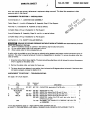 3
3
-
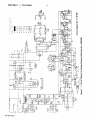 4
4
-
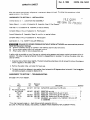 5
5
-
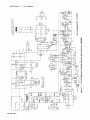 6
6
-
 7
7
-
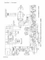 8
8
-
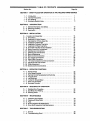 9
9
-
 10
10
-
 11
11
-
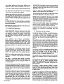 12
12
-
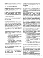 13
13
-
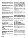 14
14
-
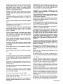 15
15
-
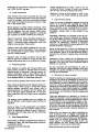 16
16
-
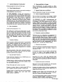 17
17
-
 18
18
-
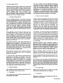 19
19
-
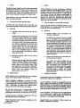 20
20
-
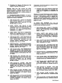 21
21
-
 22
22
-
 23
23
-
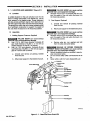 24
24
-
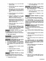 25
25
-
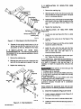 26
26
-
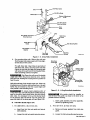 27
27
-
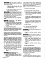 28
28
-
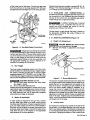 29
29
-
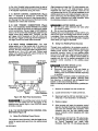 30
30
-
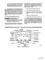 31
31
-
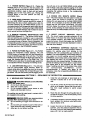 32
32
-
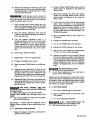 33
33
-
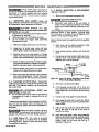 34
34
-
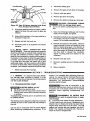 35
35
-
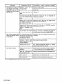 36
36
-
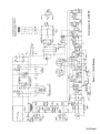 37
37
-
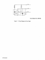 38
38
-
 39
39
-
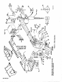 40
40
-
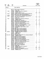 41
41
-
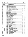 42
42
-
 43
43
-
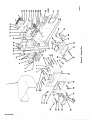 44
44
-
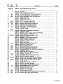 45
45
-
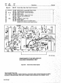 46
46
-
 47
47
-
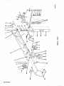 48
48
-
 49
49
-
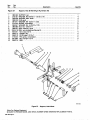 50
50
-
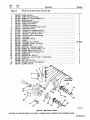 51
51
-
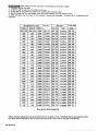 52
52
-
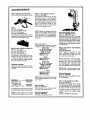 53
53
-
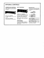 54
54
-
 55
55
-
 56
56


Miller JF923259 Le manuel du propriétaire
- Catégorie
- Système de soudage
- Taper
- Le manuel du propriétaire
- Ce manuel convient également à
dans d''autres langues
- English: Miller JF923259 Owner's manual
Documents connexes
-
Miller JE753320 Le manuel du propriétaire
-
-
-
-
-
-
-
-
-
