Porter-Cable PC13CSL Manuel utilisateur
- Catégorie
- Outils électroportatifs
- Taper
- Manuel utilisateur
Ce manuel convient également à

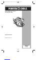
7-1/4 inch (185mm)
Circular Saw with Laser
Instruction manual
Manuel d'instructions
Manual de'instrucciones
www.portercable.com
INSTRUCTIVO DE OPERACIÓN,
CENTROS DE SERVICIO Y PÓLIZA DE
GARANTÍA.
ADVERTENCIA: LÉASE ESTE
INSTRUCTIVO ANTES DE USAR EL
PRODUCTO.
Scie circulaire de 7 1/4 po
(185 mm) avec laser
Sierra circular con láser
185 mm (7-1/4 pulgadas)
CATALOG NUMBERS
PC13CSL
PC15CSL
90539190 REV MAY 2009.qxd 5/27/09 9:22 AM Page 1

2
General Power Tool Safety Warnings
Read all safety warnings and instructions. Failure to follow the
warnings and instructions may result in electric shock, fire and/or serious injury.
Save all warnings and instructions for future reference.
The term “power tool” in the warnings refers to your mains-operated (corded)
power tool or battery-operated (cordless) power tool.
1) Work area safety
a) Keep work area clean and well lit. Cluttered or dark areas invite accidents.
b) Do not operate power tools in explosive atmospheres, such as in the
presence of flammable liquids, gases or dust. Power tools create sparks which
may ignite the dust or fumes.
c) Keep children and bystanders away while operating a power tool. Distractions
can cause you to lose control.
2) Electrical safety
a) Power tool plugs must match the outlet. Never modify the plug in any way. Do
not use any adapter plugs with earthed (grounded) power tools. Unmodified
plugs and matching outlets will reduce risk of electric shock.
b) Avoid body contact with earthed or grounded surfaces such as pipes,
radiators, ranges and refrigerators. There is an increased risk of electric shock if
your body is earthed or grounded.
c) Do not expose power tools to rain or wet conditions. Water entering a power
tool will increase the risk of electric shock.
d) Do not abuse the cord. Never use the cord for carrying, pulling or unplugging
the power tool. Keep cord away from heat, oil, sharp edges or moving parts.
Damaged or entangled cords increase the risk of electric shock.
e) When operating a power tool outdoors, use an extension cord suitable for
outdoor use. Use of a cord suitable for outdoor use reduces the risk of electric
shock.
f) If operating a power tool in a damp location is unavoidable, use a ground fault
circuit interrupter (GFCI) protected supply. Use of a GFCI reduces the risk of
electric shock.
3) Personal safety
a) Stay alert, watch what you are doing and use common sense when operating
a power tool. Do not use a power tool while you are tired or under the
influence of drugs, alcohol or medication. A moment of inattention while
operating power tools may result in serious personal injury.
b) Use personal protective equipment. Always wear eye protection. Protective
equipment such as dust mask, non-skid safety shoes, hard hat, or hearing
protection used for appropriate conditions will reduce personal injuries.
c) Prevent unintentional starting. Ensure the switch is in the off-position before
connecting to power source and/or battery pack, picking up or carrying the
tool. Carrying power tools with your finger on the switch or energizing power tools
that have the switch on invites accidents.
d) Remove any adjusting key or wrench before turning the power tool on. A
wrench or a key left attached to a rotating part of the power tool may result in
personal injury.
e) Do not overreach. Keep proper footing and balance at all times. This enables
better control of the power tool in unexpected situations.
f) Dress properly. Do not wear loose clothing or jewellery. Keep your hair,
clothing and gloves away from moving parts. Loose clothes, jewellery or long
hair can be caught in moving parts.
g) If devices are provided for the connection of dust extraction and collection
:
90539190 REV MAY 2009.qxd 5/27/09 9:22 AM Page 2

3
facilities, ensure these are connected and properly used. Use of dust collection
can reduce dust-related hazards.
4) Power tool use and care
a) Do not force the power tool. Use the correct power tool for your application.
The correct power tool will do the job better and safer at the rate for which it was
designed.
b) Do not use the power tool if the switch does not turn it on and off. Any power
tool that cannot be controlled with the switch is dangerous and must be repaired.
c) Disconnect the plug from the power source and/or the battery pack from the
power tool before making any adjustments, changing accessories, or storing
power tools. Such preventive safety measures reduce the risk of starting the power
tool accidentally.
d) Store idle power tools out of the reach of children and do not allow persons
unfamiliar with the power tool or these instructions to operate the power tool.
Power tools are dangerous in the hands of untrained users.
e) Maintain power tools. Check for misalignment or binding of moving parts,
breakage of parts and any other condition that may affect the power tool’s
operation. If damaged, have the power tool repaired before use. Many
accidents are caused by poorly maintained power tools.
f) Keep cutting tools sharp and clean. Properly maintained cutting tools with sharp
cutting edges are less likely to bind and are easier to control.
g) Use the power tool, accessories and tool bits etc., in accordance with these
instructions, taking into account the working conditions and the work to be
performed. Use of the power tool for operations different from those intended could
result in a hazardous situation.
5) Battery tool use and care
a) Recharge only with the charger specified by the manufacturer. A charger that is
suitable for one type of battery pack may create a risk of fire when used with
another battery pack.
b) Use power tools only with specifically designated battery packs. Use of any
other battery packs may create a risk of injury and fire.
c) When battery pack is not in use, keep it away from other metal objects like
paper clips, coins, keys, nails, screws, or other small metal objects that can
make a connection from one terminal to another. Shorting the battery terminals
together may cause burns or a fire.
d) Under abusive conditions, liquid may be ejected from the battery, avoid
contact. If contact accidentally occurs, flush with water. If liquid contacts
eyes, additionally seek medical help. Liquid ejected from the battery may cause
irritation or burns.
6) Service
a) Have your power tool serviced by a qualified repair person using only
identical replacement parts. This will ensure that the safety of the power tool is
maintained.
ADDITIONAL SPECIFIC SAFETY RULES
SAFETY INSTRUCTIONS FOR ALL SAWS
a. Keep hands away from cutting area and the blade. Keep your second hand on
auxiliary handle, or motor housing. If both hands are holding the saw, they
cannot be cut by the blade.
b. Do not reach underneath the workpiece. The guard cannot protect you from the
blade below the workpiece.
c. Adjust the cutting depth to the thickness of the workpiece. Less than a full
tooth of the blade teeth should be visible below the workpiece.
:
90539190 REV MAY 2009.qxd 5/27/09 9:22 AM Page 3

4
d. Never hold piece being cut in your hands or across your leg. Secure the
workpiece to a stable platform. It is important to support the work properly to
minimize body exposure, blade binding, or loss of control.
e. Hold power tool by insulated gripping surfaces when performing an operation
where the cutting tool may contact hidden wiring or its own cord. Contact with
a "live" wire will also make exposed metal parts of the power tool "live" and shock
the operator.
f. When ripping always use a rip fence or straight edge guide. This improves the
accuracy of cut and reduces the chance of blade binding.
g. Always use blades with correct size and shape (diamond versus round) of
arbor holes. Blades that do not match the mounting hardware of the saw will run
eccentrically, causing loss of control.
h. Never use damaged or incorrect blade washers or bolt. The blade washers and
bolt were specially designed for your saw, for optimum performance and safety of
operation.
CAUSES AND OPERATOR PREVENTION OF KICKBACK:
• Kickback is a sudden reaction to a pinched, bound or misaligned saw blade, causing
an uncontrolled saw to lift up and out of the workpiece toward the operator.
• When the blade is pinched or bound tightly by the kerf closing down, the blade stalls
and the motor reaction drives the unit rapidly back toward the operator.
• If the blade becomes twisted or misaligned in the cut, the teeth at the back edge of the
blade can dig into the top surface of the wood causing the blade to climb out of the kerf
and jump back toward the operator.
Kickback is the result of saw misuse and/or incorrect operating procedures or
conditions and can be avoided by taking proper precautions as given below:
a. Maintain a firm grip with both hands on the saw and position your arms to
resist kickback forces. Position your body to either side of the blade, but not
in line with the blade. Kickback could cause the saw to jump backwards, but
kickback forces can be controlled by the operator, if proper precautions are taken.
b. When blade is binding, or when interrupting a cut for any reason, release the
trigger and hold the saw motionless in the material until the blade comes to a
complete stop. Never attempt to remove the saw from the work or pull the
saw backward while the blade is in motion or kickback may occur. Investigate
and take corrective actions to eliminate the cause of blade binding.
c. When restarting a saw in the workpiece, center the saw blade in the kerf and
check that saw teeth are not engaged into the material. If saw blade is binding,
it may walk up or kickback from the workpiece as the saw is restarted.
d. Support large panels to minimize the risk of blade pinching and kickback.
Large panels tend to sag under their own weight. Supports must be placed under
the panel on both sides, near the line of cut and near the edge of the panel.
e. Do not use dull or damaged blades. Unsharpened or improperly set blades
produce narrow kerf causing excessive friction, blade binding and kickback.
f. Blade depth and bevel adjusting locking levers must be tight and secure
before making cut. If blade adjustment shifts while cutting, it may cause binding
and kickback.
g. Use extra caution when making a "plunge cut" into existing walls or other
blind areas. The protruding blade may cut objects that can cause kickback.
LOWER GUARD SAFETY INSTRUCTIONS
a. Check lower guard for proper closing before each use. Do not operate the
saw if lower guard does not move freely and close instantly. Never clamp or
tie the lower guard into the open position. If saw is accidentally dropped, lower
guard may be bent. Raise the lower guard with the retracting handle and make sure
it moves freely and does not touch the blade or any other part, in all angles and
depths of cut.
b. Check the operation of the lower guard spring. If the guard and the spring are
not operating properly, they must be serviced before use. Lower guard may
operate sluggishly due to damaged parts, gummy deposits, or a build-up of debris.
c. Lower guard should be retracted manually only for special cuts such as
90539190 REV MAY 2009.qxd 5/27/09 9:22 AM Page 4

5
"plunge cuts" and "compound cuts." raise lower guard by retracting handle
and as soon as blade enters the material, the lower guard must be released.
For all other sawing, the lower guard should operate automatically.
d. Always observe that the lower guard is covering the blade before placing saw
down on bench or floor. An unprotected, coasting blade will cause the saw to walk
backwards, cutting whatever is in its path. Be aware of the time it takes for the
blade to stop after switch is released.
SAFETY INSTRUCTIONS - LASERS
Laser radiation, avoid direct eye exposure, serious eye injury can result.
• Do not use optical tools such as a telescope or transit to view the laser beam.
• Position the laser so unintentional eye contact will be avoided.
• Do not operate the laser around children or allow children to operate the laser / power
tool.
• Do not disassemble. Modifying the product in any way can increase the risk of laser
radiation.
Use of controls or adjustments or performance of procedures other than
those specified in this manual may result in hazardous laser radiation exposure.
• Do not adjust the laser, when the battery is inserted in the circular saw.
• Do not operate in explosive atmospheres, such as in the presence of flammable
liquids, gases, or dust.
• Store idle product out of reach of children and other untrained persons. Lasers / power
tools are dangerous in the hands of untrained users.
• Use only accessories that are recommended by the manufacturer for your model.
Accessories that may be suitable for one laser / power tool, may create a risk of injury
when used on another laser / power tool.
• Repairs and servicing MUST be performed by a qualified repair facility. Repairs
performed by unqualified personnel could result in serious injury.
• Do not remove or deface warning labels. Removing labels increases the risk of
exposure to radiation.
• For indoor use only.
• This product is intended for use in a temperature range of 41°F(5°C) - 104°F(40°C).
Some dust created by power sanding, sawing, grinding, drilling,
and other construction activities contains chemicals known to the state of
California to cause cancer, birth defects or other reproductive harm. Some
examples of these chemicals are:
• lead from lead-based paints,
• crystalline silica from bricks and cement and other masonry products, and
• arsenic and chromium from chemically-treated lumber.
Your risk from these exposures varies, depending on how often you do this type of work.
To reduce your exposure to these chemicals: work in a well ventilated area, and work
with approved safety equipment, such as those dust masks that are specially designed
to filter out microscopic particles.
•Avoid prolonged contact with dust from power sanding, sawing, grinding, drilling,
and other construction activities. Wear protective clothing and wash exposed
areas with soap and water. Allowing dust to get into your mouth, eyes, or lay on the
skin may promote absorption of harmful chemicals.
Use of this tool can generate and/or disperse dust, which may
cause serious and permanent respiratory or other injury. Always use NIOSH/OSHA
approved respiratory protection appropriate for the dust exposure. Direct particles away
from face and body.
Always wear proper personal hearing protection that conforms to
ANSI S12.6 (S3.19) during use. Under some conditions and duration of use, noise from
this product may contribute to hearing loss.
ALWAYS use safety glasses. Everyday eyeglasses are NOT safety
glasses. Also use face or dust mask if cutting operation is dusty. ALWAYS WEAR
CERTIFIED SAFETY EQUIPMENT:
:
:
:
:
:
:
90539190 REV MAY 2009.qxd 5/27/09 9:22 AM Page 5

6
• ANSI Z87.1 eye protection (CAN/CSA Z94.3),
• ANSI S12.6 (S3.19) hearing protection,
• NIOSH/OSHA/MSHA respiratory protection.
SAFETY GUIDELINES - DEFINITIONS
It is important for you to read and understand this manual. The information it contains
relates to protecting YOUR SAFETY and PREVENTING PROBLEMS. The symbols
below are used to help you recognize this information.
Indicates an imminently hazardous situation which, if not avoided, will
result in death or serious injury.
Indicates a potentially hazardous situation which, if not avoided, could
result in death or serious injury.
Indicates a potentially hazardous situation which, if not avoided, may
result in minor or moderate injury.
Used without the safety alert symbol indicates a potentially hazardous
situation which, if not avoided, may result in property damage.
SYMBOLS
• The label on your tool may include the following symbols. The symbols and their
definitions are as follows:
V..................volts A ..................amperes
Hz................hertz W..................watts
min ..............minutes ................alternating current
............direct current no ................no load speed
................Class I Construction ..................earthing terminal
(grounded) ................safety alert symbol
................Class II Construction .../min or rpm..revolutions or reciprocation
(double insulated) per minute
The label on your laser may include the following symbols.
V ................................volts mW......................milliwatts
nm..............................wavelength in
nanometers
IIIa..............................Class IIlA Laser
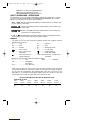
• When using an extension cord, be sure to use one heavy enough to carry the current
your product will draw. An undersized cord will cause a drop in line voltage resulting in
loss of power and overheating. The following table shows the correct size to use
depending on cord length and nameplate ampere rating. If in doubt, use the next
heavier gage. The smaller the gage number, the heavier the cord.
Recommended Minimum Wire Size for Extension Cords
Total Length of Cord
25 ft. 50 ft. 75 ft. 100 ft. 125 ft. 150 ft. 175 ft.
7.6 m 15.2 m 22.9 m 30.5 m 38.1 m 45.7 m 53.3 m
Wire Size AWG
18 18 16 16 14 14 12
:
:
:
:
90539190 REV MAY 2009.qxd 5/27/09 9:22 AM Page 6

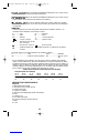
7
For your
convenience
and safety, the
following labels
are on your
laser.
3
1
2
4
5
6
7
8
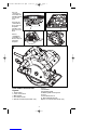
A
FUNCTIONAL DESCRIPTION
Figure A
1. On/off switch
2. Laser on/off switch
3. Main handle
4. Secondary handle
5. Spindle lock button (PC15CSL only)
6. Shoe
7. Saw blade
8. Saw blade guard
8a. Blade guard retracting lever
9. Laser
10. Saw blade wrench
11. Bevel adjustment knob
Rip fence not shown (PC15CSL only)
9
10
11
8A
Pour plus de
commodité et
de sécurité, les
étiquettes
suivantes sont
apposées sur le
laser.
Para su
comodidad y
seguridad, el
láser incluye las
siguientes
etiquetas.
90539190 REV MAY 2009.qxd 5/27/09 9:22 AM Page 7

8
F
C
E
B
D
G
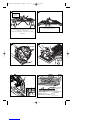
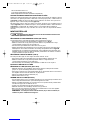
Support work near cut
Soutenir la pièce près de la ligne de coupe.
Apoye la pieza cerca del corte
Wrong
Incorrect
Incorrecto
Material bends on blade causing heavy loads or kickback
Le matériau plie au contact de la lame causant de lourdes
surcharges ou des rebonds.
El material oprime el disco ocasionando sobrecarga o
contragolpe
12
13
Tip of tooth
Pointe en
bois
Punta de la
madera
Surface of wood
Surface de bois
Superficie de la madera
90539190 REV MAY 2009.qxd 5/27/09 9:22 AM Page 8


11
SUPPORTING LARGE PANELS / SECURING WORKPIECE
Support large panels to minimize the risk of blade pinching and kickback. Large panels
tend to sag under their own weight as shown in figure B. Supports must be placed
under the panel on both sides, near the line of cut and near the edge of the panel
(figure C).
Never hold piece being cut in your hands or across your leg (figure D). Secure the
workpiece to a stable platform as shown in figure E. It is important to support the work
properly to minimize body exposure, blade binding, or loss of control.
ASSEMBLY/ SET-UP
Always unplug saw from power supply before any of the following
operations.
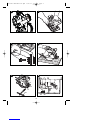
ADJUSTING THE DEPTH OF CUT (FIGURE F & G)
The depth of cut should be set according to the thickness of the workpiece.
• Loosen the lever (12) to unlock the saw shoe (figure F).
• Move the saw shoe (6) into the desired position. The corresponding depth of cut can
be read from the scale (13).
• Tighten the lever to lock the saw shoe in place.
• Set depth adjustment of saw such that one tooth of the blade projects below the
workpiece as shown in figure G. Setting the saw at the proper cutting depth keeps
blade friction to a minimum, removes sawdust from between the blade teeth, results in
cooler, faster sawing and reduces the chance of kickback.
ADJUSTING THE BEVEL ANGLE (FIGURE H)
This tool can be set to bevel angles between 0° and 45°.
• Loosen the locking knob (14) to unlock the saw shoe.
• Move the saw shoe (6) into the desired position. The corresponding bevel angle can
be read from the scale (15).
• Tighten the locking knob to lock the saw shoe in place.
ATTACHING AND REMOVING THE BLADE
REMOVING THE BLADE (PC15CSL) (FIGURE I & J)
• Keep the spindle lock button (5) depressed and rotate the blade until the spindle lock
engages.
• Loosen and remove the blade retaining screw (16) by turning it counterclockwise
using the wrench (10) supplied.
• Remove the outer washer (17).
• Remove the saw blade (7).
ATTACHING THE BLADE (PC15CSL)
• Place the saw blade (7), on the spindle shaft, making sure that the arrow on the
blade points in the same direction as the arrow on the tool.
• Fit the outer washer (17) on the spindle, with the raised part pointing away from the
saw blade.
• Insert the blade retaining screw (16) into the hole.
• Keep the spindle lock button (5) depressed.
• Securely tighten the blade retaining screw by turning it clockwise using the wrench
(10) supplied.
NOTE: The inner flange (18), should not be removed. If it is removed, replace it
as shown in figure J.
REMOVING THE BLADE (PC13CSL) (FIGURE K & J)
• Prevent spindle rotation by engaging the teeth of the saw blade into a piece of scrap
wood.
• Loosen and remove the blade retaining screw (16) by turning it counterclockwise
using the wrench (10) supplied.
• Remove the outer washer (17).
• Remove the saw blade (7).
:
90539190 REV MAY 2009.qxd 5/27/09 9:22 AM Page 11

12
ATTACHING THE BLADE (PC13CSL)
• Place the saw blade (7), on the spindle shaft, making sure that the arrow on the blade
points in the same direction as the arrow on the tool.
• Fit the outer washer (17) on the spindle, with the raised part pointing away from the
saw blade.
• Insert the blade retaining screw (16) into the hole.
• Prevent spindle rotation by engaging the teeth of the saw blade into a piece of scrap
wood.
• Securely tighten the blade retaining screw by turning it clockwise using the wrench
(10) supplied.
NOTE: The inner flange (18), should not be removed. If it is removed, replace it
as shown in figure J.
To reduce the risk of serious personal injury, read, understand and follow
all important safety warnings and instructions prior to using tool.
GENERAL CUTS (IMPORTANT: READ SAFETY WARNINGS AND INSTRUCTIONS. )
GUARD AGAINST KICKBACK
With unit unplugged, follow all assembly, adjustment and set up instructions.
Make sure lower guard operates. Select the proper blade for the material to be cut.
• Measure and mark work for cutting.
• Support and secure work properly (See Safety Rules and Instructions).
• Use appropriate and required safety equipment (See Safety Rules).
• Secure and maintain work area (See Safety Rules).
• With plug inserted and guard closed, make sure switch turns saw on and off.
It is important to support the work properly and to hold the saw firmly to
prevent loss of control which could cause personal injury. Figure E illustrates
recommended hand position.
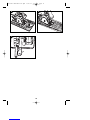
ATTACHING AND REMOVING THE RIP FENCE (INCLUDED WITH PC15CSL) FIG. L)
The rip fence is used to saw in a straight line parallel to the edge of the workpiece.
ATTACHING
• Loosen the locking knob (19).
• Insert the rip fence (20) through the openings (21).
• Slide the rip fence into the desired position.
• Tighten the locking knob.
REMOVING
• Loosen the locking knob.
• Pull the rip fence out of the tool.
NOTE: If you do not have a proper fitting fence, use a straight edge guide in contact with the
edge of the shoe to improve accuracy of cut and reduce the possibility of binding and
kickback.
OPERATION
SWITCH
• To operate the tool, depress the trigger switch (1). The tool will continue to run as long
as the trigger is depressed.
• To turn the tool off, release the trigger switch (1). There is no provision for locking the
tool on, and the switch should never be locked on by any other means.
KERF PLATE ADJUSTMENT (FIGURE M)
The tool is equipped with a sight guide for straight cutting (22) and for 45° miter cutting
(23).
• Be sure the saw is unplugged.
• Adjust the kerf plate as described below.
• Align the left edge of the guides (22) or (23) with the cutting line.
:
:
90539190 REV MAY 2009.qxd 5/27/09 9:22 AM Page 12

13
• Keep the kerf plate aligned with the cutting line while sawing.
• Work with the shoe pressed against the workpiece.
ADJUSTING THE KERF PLATE
• Plug in the saw.
• Make a test cut halfway through a piece of scrap wood.
• Withdraw the saw so the cutting line becomes visible.
• While keeping the saw in this position, unplug the saw and loosen the kerf plate on
the saw shoe.
• Align the 0° mark (22) on the kerf plate with the cutting line. When adjusting for 45°
miter cuts, align the 45° mark (23) on the kerf plate with the cutting line.
• Secure the kerf plate using the screw (24).
LASER LINE
LASER RADIATION. Never aim the beam at a workpiece with a
reflective surface. Bright shiny reflective sheet steel or similar reflective surfaces are
not recommended for laser use. Reflective surfaces could direct the beam back toward
the operator.
LASER RADIATION. AVOID DIRECT EYE EXPOSURE. Do not stare
into the laser light source. Never aim light at another person or object other than
the workpiece. Laser light can damage your eyes.
DO NOT use tinted glasses to enhance the laser light. Tinted glasses
will reduce overall vision for the application and interfere with the normal operation of
the tool.
LASER SWITCH (FIGURE N)
To turn the laser on, push forward on the laser on/off switch (2) to activate the laser line
(25) as shown in figure N.
TO USE THE LASER LINE
• Mark the line that you intend to cut on the workpiece.
• Adjust the depth and angle of cut as required.
• Push the laser on/off switch (2) to the forward “ON” position and project the laser
beam.
• Depress the saw trigger switch (1) and allow the blade to reach maximum speed.
• Place the saw shoe on the workpiece. Align the laser line with the mark on the
workpiece and slowly push the saw forward keeping the laser line on the mark.
• Upon completion of the cut, release the trigger and allow the saw blade to come to a
complete stop before switching off the laser.
SAWING
To reduce the risk of serious personal injury, always hold the tool with
both hands.
• Let the blade run freely for a few seconds before starting the cut.
• Apply only a gentle pressure to the tool while performing the cut.
• Work with the shoe pressed against the workpiece.
HINTS FOR OPTIMUM USE
• As some splintering along the line of cut on the top side of the workpiece cannot be
avoided, cut on the side where splintering is acceptable.
• Where splintering is to be minimized, e.g. when cutting laminates, clamp a piece of
plywood onto the top of the workpiece.
POCKET CUTTING (FIGURE O)
POCKET CUTTING IS USED TO CUT A HOLE IN A PIECE OF MATERIAL WITHOUT
CUTTING FROM THE SIDE.
• Measure and mark work.
:
:
:
:
90539190 REV MAY 2009.qxd 5/27/09 9:22 AM Page 13

14
• Tilt saw forward and rest front of the shoe on material to be cut. Align so that cut will
begin at the back of the drawn rectangle shown in figure O.
• Using the retracting lever, retract blade guard to an upward position, with the blade
just clearing the material, start motor and gradually lower the saw into the material.
As blade starts cutting the material, release the retracting lever immediately.
• Never tie the blade guard in a raised position.
• When the shoe rests flat on the material being cut, complete the cut in forward direction.
• Allow the blade to come to a complete stop before lifting saw from material.
• When starting each new cut, repeat the above steps.
WRENCH STORAGE (FIGURE P)
The blade wrench (10) can be stored on the saw shoe as shown in figure P.
MAINTENANCE
Use only mild soap and damp cloth to clean the tool. Never let any liquid get inside the
tool; never immerse any part of the tool into a liquid.
REPLACEMENT PARTS
Use only identical replacement parts. For a parts list or to order parts, visit our service website at
www.portercable.com. You can also order parts from your nearest Porter-Cable Factory Service
Center or Porter-Cable Authorized Warranty Service Center. Or, you can call our Customer Care
Center at (888) 848-5175.
SERVICE AND REPAIRS
All quality tools will eventually require servicing and/or replacement of parts. For information about
Porter-Cable, its factory service centers or authorized warranty service centers, visit our website at
www.portercable.com or call our Customer Care Center at (888) 848-5175. All repairs made by our
service centers are fully guaranteed against defective material and workmanship. We cannot
guarantee repairs made or attempted by others.
You can also write to us for information at PORTER-CABLE, 4825 Highway 45 North, Jackson,
Tennessee 38305 - Attention: Product Service. Be sure to include all of the information shown on
the nameplate of your tool (model number, type, serial number, etc.).
ACCESSORIES
Since accessories, other than those offered by Porter-Cable, have not
been tested with this product, use of such accessories with this tool could be
hazardous. To reduce the risk of injury, only Porter-Cable recommended accessories
should be used with this product.
A complete line of accessories is available from your Porter-Cable Factory Service
:
:
TROUBLESHOOTING
Problem Possible Cause Possible Solution
• Unit will not start. • Cord not plugged in. • Plug tool into a working outlet.
• Circuit fuse is blown. • Replace circuit fuse. (If the
product repeatedly causes the
circuit fuse to blow, discontinue
use immediately and have it
serviced at a Porter Cable
service center or authorized
servicer.)
• Circuit breaker is tripped. • Reset circuit breaker. (If the
product repeatedly causes the
circuit breaker to trip,
discontinue use immediately
and have it serviced at a Porter
Cable service center or
authorized servicer.)
• Cord or switch is damaged. • Have cord or switch replaced
at a Porter Cable Service
Center or Authorized Servicer
For assistance with your product, visit our website at www.porter-cable.com for a list of
service centers, or call the Porter-Cable Customer Care Center at (888) 848-5175.
90539190 REV MAY 2009.qxd 5/27/09 9:22 AM Page 14

15
Center or a Porter-Cable Authorized Warranty Service Center. Please visit our Web
Site www.portercable.com for a catalog or for the name of your nearest supplier.
THREE YEAR LIMITED WARRANTY
PORTER-CABLE will repair or replace, without charge, any defects due to faulty
materials or workmanship for three years from the date of purchase for tools (two years
for batteries). This warranty does not cover part failure due to normal wear or tool
abuse. For further detail of warranty coverage and warranty repair information, visit
www.portercable.com or call (888) 848-5175. This warranty does not apply to
accessories or damage caused where repairs have been made or attempted by others.
This warranty gives you specific legal rights and you may have other rights which vary
in certain states or provinces.
In addition to the warranty, PORTER-CABLE tools are covered by our:
1 YEAR FREE SERVICE: PORTER-CABLE will maintain the tool and replace worn
parts caused by normal use, for free, any time during the first year after purchase.
90 DAY MONEY BACK GUARANTEE: If you are not completely satisfied with the
performance of your PORTER-CABLE Power Tool for any reason, you can return it
within 90 days from the date of purchase with a receipt for a full refund – no questions asked.
LATIN AMERICA: This warranty does not apply to products sold in Latin America. For
products sold in Latin America, see country specific warranty information contained in
the packaging, call the local company or see website for warranty information.
To register your tool for warranty service visit our website at www.portercable.com.
WARNING LABEL REPLACEMENT
If your warning labels become illegible or are missing, call (888) 848-5175 for a free
replacement.
The following are PORTER-CABLE trademarks for one or more power tools and accessories: a
gray and black color scheme; a “four point star” design; and three contrasting/outlined longitudinal
stripes. The following are also trademarks for one or more Porter-Cable and Delta products: 2 BY
4®, 890™, Air America®, AIRBOSS™, Auto-Set®, B.O.S.S.®, Bammer®, Biesemeyer®, Builders
Saw®, Charge Air®, Charge Air Pro®, CONTRACTOR SUPERDUTY®, Contractor's Saw®,
Delta®, DELTA®, Delta Industrial®, DELTA MACHINERY & DESIGN™, Delta Shopmaster and
Design®, Delta X5®, Deltacraft®, DELTAGRAM®, Do It. Feel It.®, DUAL LASERLOC AND
DESIGN®, EASY AIR®, EASY AIR TO GO™, ENDURADIAMOND®, Ex-Cell®, Front Bevel
Lock®, Get Yours While the Sun Shines®, Grip to Fit®, GRIPVAC™, GTF®, HICKORY
WOODWORKING®, Homecraft®, HP FRAMER HIGH PRESSURE®, IMPACT SERIES™,
Innovation That Works®, Jet-Lock®, Job Boss®, Kickstand®, LASERLOC®, LONG-LASTING
WORK LIFE®, MAX FORCE™, MAX LIFE®, Micro-Set®, Midi-Lathe®, Monsoon®, MONSTER-
CARBIDE™, Network®, OLDHAM®, Omnijig®, PC EDGE®, Performance Crew™, Performance
Gear®, Pocket Cutter®, Porta-Band®, Porta-Plane®, Porter Cable®, Porter-Cable Professional
Power Tools®, Powerback®, POZI-STOP™, Pressure Wave®, PRO 4000®, Proair®, Quicksand
and Design®, Quickset II®, QUIET DRIVE TECHNOLOGY™, QUIET DRIVE TECHNOLOGY
AND DESIGN™, Quik-Change®, QUIK-TILT®, RAPID-RELEASE™, RAZOR®, Redefining
Performance®, Riptide®, Safe Guard II®, Sand Trap and Design®, Sanding Center®, Saw Boss®,
Shop Boss®, Sidekick®, Site Boss®, Speed-Bloc®, Speedmatic®, Stair Ease®, Steel Driver
Series®, SUPERDUTY®, T4 & DESIGN®, THE AMERICAN WOODSHOP®, THE
PROFESSIONAL EDGE®, Thin-Line®, Tiger Saw®, TIGERCLAW®, TIGERCLAW AND
DESIGN®, Torq-Buster®, TRU-MATCH®, T-Square®, Twinlaser®, Unifence®, Uniguard®,
UNIRIP®, UNISAW®, UNITED STATES SAW®, Veri-Set®, Versa-Feeder®, VIPER®, VT™, VT
RAZOR™, Water Driver®, WATER VROOM®, Waveform®, Whisper Series®, X5®, YOUR
ACHIEVEMENT. OUR TOOLS.® Trademarks noted with ® are registered in the United States
Patent and Trademark Office and may also be registered in other countries. Other trademarks may
apply.
4825 Highway 45 North Jackson, Tennessee 38305 (888) 848-5175 www.portercable.com
TECHNICAL SPECIFICATIONS OF LASER:
Laser diode wavelength: 633-670nm (red color)
Laser Class: IIIa
Operating temperature: 41°F (5°C) - 104° F (40°C)
Accuracy: +/- 1.8mm at every 300 mm
90539190 REV MAY 2009.qxd 5/27/09 9:22 AM Page 15


17
Avertissements de sécurité généraux pour les outils
électriques
Lire tous les avertissements de sécurité et toutes les
directives. Le non-respect des avertissements et des directives pourrait se
solder par un choc électrique, un incendie et/ou une blessure grave.
Conserver tous les avertissements et toutes les directives pour un usage
ultérieur.
Le terme «outil électrique» cité dans les avertissements se rapporte à votre
outil électrique à alimentation sur secteur (avec fil) ou par piles (sans fil).
1) Sécurité du lieu de travail
a) Tenir la zone de travail propre et bien éclairée. Les endroits sombres sont
souvent des causes d'accidents.
b) Ne pas faire fonctionner d’outils électriques dans un milieu déflagrant, soit en
présence de liquides inflammables, de gaz ou de poussière. Les outils
électriques produisent des étincelles qui peuvent enflammer la poussière ou les
vapeurs.
c) Éloigner les enfants et les curieux au moment d’utiliser un outil électrique.
Une distraction pourrait vous en faire perdre la maîtrise.
2) Sécurité en matière d’électricité
a) Les fiches des outils électriques doivent correspondre à la prise. Ne jamais
modifier la fiche en aucune façon. Ne jamais utiliser de fiche d’adaptation avec
un outil électrique mis à la terre. Le risque de choc électrique sera réduit par
l’utilisation de fiches non modifiées correspondant à la prise.
b) Éviter tout contact physique avec des surfaces mises à la terre comme des
tuyaux, des radiateurs, des cuisinières et des réfrigérateurs. Le risque de choc
électrique est plus élevé si votre corps est mis à la terre.
c) Ne pas exposer les outils électriques à la pluie ou à d'autres conditions où il
pourrait être mouillé. La pénétration de l’eau dans un outil électrique augmente le
risque de choc électrique.
d) Ne pas utiliser abusivement le cordon d’alimentation. Ne jamais utiliser le
cordon pour transporter, tirer ou débrancher un outil électrique. Tenir le cordon
éloigné de la chaleur, de l’huile, des bords tranchants ou des pièces mobiles.
Les cordons endommagés ou emmêlés augmentent les risques de choc électrique.
e) Pour l’utilisation d’un outil électrique à l’extérieur, se servir d’une rallonge
convenant à une telle utilisation. L’utilisation d’une rallonge conçue pour
l’extérieur réduit les risques de choc électrique.
f) S’il est impossible d’éviter l’utilisation d’un outil électrique dans un endroit
humide, brancher l’outil dans une prise ou sur un circuit d’alimentation dotés
d’un disjoncteur de fuite à la terre (GFCI). L’utilisation de ce type de disjoncteur
réduit les risques de choc électrique.
3) Sécurité personnelle
a) Être vigilant, surveiller le travail effectué et faire preuve de jugement
lorsqu’un outil électrique est utilisé. Ne pas utiliser d’outil électrique en cas
de fatigue ou sous l’influence de drogues, d’alcool ou de médicaments. Un
simple moment d’inattention en utilisant un outil électrique peut entraîner des
blessures corporelles graves.
b) Utiliser des équipements de protection individuelle. Toujours porter une
protection oculaire. L’utilisation d’équipements de protection comme un masque
antipoussière, des chaussures antidérapantes, un casque de sécurité ou des
protecteurs auditifs lorsque la situation le requiert réduira les risques de blessures
corporelles.
c) Empêcher les démarrages intempestifs. S’assurer que l’interrupteur se trouve
à la position d’arrêt avant de relier l’outil à une source d’alimentation et/ou
d’insérer un bloc-piles, de ramasser ou de transporter l’outil. Transporter un outil
électrique alors que le doigt repose sur l’interrupteur ou brancher un outil électrique
dont l’interrupteur est à la position de marche risque de provoquer un accident.
90539190 REV MAY 2009.qxd 5/27/09 9:22 AM Page 17

18
d) Retirer toute clé de réglage ou clé standard avant de démarrer l’outil. Une clé
standard ou une clé de réglage attachée à une partie pivotante peut causer des
blessures.
e) Ne pas trop tendre les bras. Conserver son équilibre en tout temps. Cela
permet de mieux maîtriser l’outil électrique dans les situations imprévues.
f) S’habiller de manière appropriée. Ne pas porter de vêtements amples ni de
bijoux. Garder les cheveux, les vêtements et les gants à l’écart des pièces
mobiles. Les vêtements amples, les bijoux ou les cheveux longs risquent de rester
coincés dans les pièces mobiles.
g) Si des composants sont fournis pour le raccordement de dispositifs de
dépoussiérage et de ramassage, s’assurer que ceux-ci sont bien raccordés et
utilisés. L’utilisation d’un dispositif de dépoussiérage peut réduire les dangers
engendrés par les poussières.
4) Utilisation et entretien d’un outil électrique
a) Ne pas forcer un outil électrique. Utiliser l’outil électrique approprié à
l’application. L’outil électrique approprié effectuera un meilleur travail, de façon
plus sûre et à la vitesse pour laquelle il a été conçu.
b) Ne pas utiliser un outil électrique dont l’interrupteur est défectueux. Tout outil
électrique dont l’interrupteur est défectueux est dangereux et doit être réparé.
c) Débrancher la fiche du secteur ou le bloc-piles de l’outil électrique avant de
faire tout réglage ou changement d’accessoire, ou avant de ranger l’outil
électrique. Ces mesures préventives réduisent les risques de démarrage
accidentel de l’outil électrique.
d) Ranger les outils électriques hors de la portée des enfants, et ne permettre à
aucune personne n’étant pas familière avec un outil électrique (ou son manuel
d’instruction) d’utiliser ce dernier. Les outils électriques deviennent dangereux
entre les mains d’utilisateurs inexpérimentés.
e) Entretenir les outils électriques. Vérifier les pièces mobiles pour s’assurer
qu’elles sont bien alignées et tournent librement, qu’elles sont en bon état et
ne sont affectées par aucun trouble susceptible de nuire au bon
fonctionnement de l’outil électrique. En cas de dommage, faire réparer l’outil
électrique avant toute nouvelle utilisation. Beaucoup d’accidents sont causés par
des outils électriques mal entretenus.
f) S’assurer que les outils de coupe sont aiguisés et propres. Les outils de coupe
bien entretenus et affûtés sont moins susceptibles de se coincer et sont plus faciles
à contrôler.
g) Utiliser l’outil électrique, les accessoires, les forets, etc. conformément aux
présentes directives en tenant compte des conditions de travail et du travail à
effectuer. L’utilisation d’un outil électrique pour toute opération autre que celle pour
laquelle il a été conçu est dangereuse.
5) Utilisation et entretien du bloc-piles
a) Ne recharger l’outil qu’au moyen du chargeur précisé par le fabricant.
L’utilisation d’un chargeur qui convient à un type de bloc-piles risque de provoquer
un incendie s’il est utilisé avec un autre type de bloc-piles.
b) Utiliser les outils électriques uniquement avec les blocs-piles conçus à cet effet.
L’utilisation de tout autre bloc-piles risque de causer des blessures ou un incendie.
c) Lorsque le bloc-piles n’est pas utilisé, le tenir éloigné des objets métalliques,
notamment des trombones, de la monnaie, des clés, des clous, des vis, etc.,
qui peuvent établir une connexion entre les deux bornes. Le court-circuit des
bornes du bloc-piles risque de provoquer des étincelles, des brûlures ou un incendie.
d) En cas d’utilisation abusive, le liquide peut gicler hors du bloc-piles, éviter tout
contact. Si un contact accidentel se produit, laver à grande eau. Si le liquide
entre en contact avec les yeux, obtenir des soins médicaux. Le liquide qui gicle
hors du bloc-piles peut provoquer des irritations ou des brûlures.
6) Réparation
a) Faire réparer l’outil électrique par un réparateur professionnel en n’utilisant
que des pièces de rechange identiques. Cela permettra de maintenir une
utilisation sécuritaire de l’outil électrique.
90539190 REV MAY 2009.qxd 5/27/09 9:22 AM Page 18

19
RÈGLES DE SÉCURITÉ SPÉCIFIQUES SUPPLÉMENTAIRES
CONSIGNES DE SÉCURITÉ POUR TOUTES LES SCIES
a. Gardez les mains à distance de la zone de coupe et de la lame. Gardez une
de vos mains sur la poignée auxiliaire ou sur le carter du moteur. Si vous tenez
la scie de vos deux mains, elles ne peuvent pas être coupées par la lame.
b. N'essayez pas de tenir le dessous de l'ouvrage. Le protège-lame ne peut pas
vous protéger de la lame en dessous de l'ouvrage.
c. Ajustez la profondeur de coupe à l'épaisseur de l'ouvrage. Moins d'une dent
entière de lame devrait être visible en dessous de l'ouvrage.
d. Ne tenez jamais dans vos mains ou sur vos genoux un ouvrage qui est en
cours de coupe. Fixez votre ouvrage sur une plateforme stable. Il est important
de soutenir correctement l'ouvrage afin de minimiser l'exposition du corps à la
lame, le risque de coincement de la lame ou la perte de contrôle de l'outil.
e. Tenez l'outil électrique par ses surfaces de préhension isolantes quand vous
réalisez une opération au cours de laquelle l'outil de coupe pourrait entrer en
contact avec des câbles dissimulés ou avec son propre cordon électrique. Le
contact avec un fil sous tension mettra également sous tension toutes les pièces
métalliques exposées et donnera un choc électrique à l'utilisateur de l'outil.
f. Pendant les coupes de refente, utilisez toujours un guide de refente ou un
guide à bord droit. Ceci augmente toujours l'exactitude de la coupe et diminue la
possibilité de coincement de la lame.
g. Utilisez toujours des lames dont l'alésage central est de la taille et de la
forme appropriées (soit en forme de diamant, soit en forme de rond). Les
lames qui ne correspondent pas aux pièces de montage de la cie tourneront de
façon excentrique, ce qui causera une perte de contrôle de l'outil.
h. Ne vous servez jamais de rondelles ou de boulons de lames qui sont
endommagés ou inappropriés. Les rondelles et le boulon de lame ont été conçus
spécifiquement pour votre scie dans le but d'assurer une performance optimale et
un fonctionnement sans danger.
CAUSES DES REBONDS ET MÉTHODES DE PRÉVENTION POUVANT ÊTRE
UTILISÉES PAR L'UTILISATEUR :
• Le rebond est une réaction subite (causée par une lame de scie pincée, coincée ou
mal alignée) qui peut entraîner le soulèvement d'une scie non contrôlée, sa sortie de
l'ouvrage et sa projection en direction de l'utilisateur.
• Si la lame est pincée ou coincée fortement pendant l'abaissement de la scie, la lame
se cale et le moteur réagit en entraînant rapidement l'outil vers l'arrière dans la
direction de l'opérateur.
• Si la lame se tord ou perd son alignement correct au cours de la coupe, les dents sur
le bord arrière de la lame peuvent entamer la surface supérieure du bois, forçant ainsi
la lame à sortir du trait de scie et à « sauter » vers l'arrière en direction de l'opérateur.
Le rebond est la conséquence d'une mauvaise utilisation de la scie et/ou de
procédures ou de conditions incorrectes, et il peut être évité en prenant les précautions
qui sont décrites ci-dessous :
a. Maintenez fermement la scie avec vos deux mains et positionnez vos bras de
façon à résister aux forces de rebond. Les forces de rebond peuvent être
contrôlées par l'utilisateur quand les précautions appropriées sont prises.
b. En cas de coincement de la lame ou d'interruption d'une coupe pour une
raison quelconque, relâchez la gâchette et tenez la scie immobile dans
l'ouvrage jusqu'à ce que la lame se soit immobilisée complètement. Ne tentez
jamais de retirer la scie de l'ouvrage ou de la tirer vers l'arrière pendant que
la lame est en mouvement, car un rebond risquerait de se produire. Évaluez la
situation et prenez les mesures correctives nécessaires pour éliminer la cause du
coincement de la lame.
c. Lorsque vous remettez une scie en marche quand l'ouvrage est présent,
centrez la lame de scie dans le trait de scie et vérifiez que les dents de la
lame ne sont pas engagées dans le matériau de l'ouvrage. Si la lame de scie
se coince, elle peut grimper hors de l'ouvrage ou rebondir sur celui-ci quand la scie
est remise en marche.
90539190 REV MAY 2009.qxd 5/27/09 9:22 AM Page 19

20
d. Soutenez les panneaux de grande taille de façon à minimiser le risque de
pincement et de rebond de la lame. Les panneaux de grande taille ont tendance
à s'affaisser sous leur propre poids. Des supports doivent être placés des deux
côtés sous le panneau, à proximité de la ligne de coupe et à proximité du rebord
du panneau.
e. N'utilisez pas de lame émoussée ou endommagée. Des lames non aiguisées
ou mal installées produisent un trait de scie étroit qui cause une friction excessive,
le coincement de la lame et un effet de rebond.
f. Les leviers de réglage de la profondeur et de l'angle de coupe de la lame
doivent être bien serrés et assujettis avant de réaliser une coupe. Une
modification du réglage de la lame pendant la coupe risque d'entraîner un
coincement et un rebondissement de la lame.
g. Procédez avec une prudence supplémentaire quand vous réalisez une coupe
« en plongée » dans des murs déjà en place ou dans des pièces sans issue.
La lame saillante peut couper des objets, et ceci peut entraîner un rebond.
CONSIGNES DE SÉCURITÉ RELATIVES AU PROTÈGE-LAME
INFÉRIEUR
a. Inspectez le protège-lame inférieur avant chaque utilisation pour vous
assurer qu'il se ferme correctement. Ne faites pas fonctionner la scie si le
protège-lame inférieur ne se déplace pas librement et ne se ferme pas
instantanément. Ne forcez jamais le protège-lame inférieur dans la position
ouverte à l'aide d'un collier de serrage ou d'une attache. Il est possible que le
protègelame inférieur se torde en cas de chute accidentelle de la scie. Soulevez le
protège-lame inférieur à l'aide de la poignée rétractable et assurez-vous qu'il se
déplace sans problème et qu'il ne touche pas la lame ou une autre pièce, quel que
soit l'angle ou la profondeur de la coupe.
b. Vérifiez le fonctionnement du ressort du protège-lame inférieur. Si le
protège-lame inférieur et le ressort ne fonctionnent pas correctement, ils
doivent être réparés avant l'emploi. Le protège-lame inférieur peut parfois mal
fonctionner à cause de pièces endommagées, d'accumulation de résine ou de débris.
c. Le protège-lame inférieur doit être rétracté à la main uniquement à l'occasion
de coupes spéciales telles que les « coupes en plongée » ou les « coupes
composées ». Soulevez le protège-lame inférieur à l'aide la poignée
rétractable et relâchez-le dès que la lame pénètre dans le matériau de
l'ouvrage. Pour toute autre opération de sciage, le protège-lame inférieur doit
fonctionner automatiquement.
d. Vérifiez toujours que le protège-lame inférieur couvre la lame avant de placez
la scie sur un banc ou sur le sol. Une lame non protégée qui tourne librement
entraînera le mouvement de la scie en marche arrière, ce qui provoquera la coupe
de tout se qui se trouve sur sa trajectoire. Soyez conscient du temps nécessaire à
la lame pour s'arrêter une fois que la gâchette est relâchée.
DIRECTIVES DE SÉCURITÉ POUR LASERS
rayonnement laser; éviter tout contact direct avec les yeux, des
blessures graves aux yeux peuvent en résulter.
• Ne pas utiliser d’instruments optiques comme un télescope ou un théodolite pour
observer le faisceau laser.
• Positionner le laser de sorte à éviter tout contact accidentel avec les yeux.
• Ne pas utiliser le laser près des enfants et ne pas laisser les enfants utiliser le
laser/outil électrique.
• Ne pas démonter l’appareil. Toute modification du produit peut accroître le risque de
rayonnement laser.
l’utilisation de commandes ou de réglages ou l’exécution de
procédures autres que celles précisées dans la présente peut entraîner une
exposition dangereuse au rayonnement laser.
• Ne pas régler le système laser lorsque le bloc-pile est inséré dans la scie circulaire.
• Ne pas faire fonctionner l’outil dans un environnement explosif, soit en présence de
liquides, gaz ou poussière inflammables.
90539190 REV MAY 2009.qxd 5/27/09 9:22 AM Page 20
La page charge ...
La page charge ...
La page charge ...
La page charge ...
La page charge ...
La page charge ...
La page charge ...
La page charge ...
La page charge ...
La page charge ...
La page charge ...
La page charge ...
La page charge ...
La page charge ...
La page charge ...
La page charge ...
La page charge ...
La page charge ...
La page charge ...
La page charge ...
La page charge ...
La page charge ...
La page charge ...
La page charge ...
-
 1
1
-
 2
2
-
 3
3
-
 4
4
-
 5
5
-
 6
6
-
 7
7
-
 8
8
-
 9
9
-
 10
10
-
 11
11
-
 12
12
-
 13
13
-
 14
14
-
 15
15
-
 16
16
-
 17
17
-
 18
18
-
 19
19
-
 20
20
-
 21
21
-
 22
22
-
 23
23
-
 24
24
-
 25
25
-
 26
26
-
 27
27
-
 28
28
-
 29
29
-
 30
30
-
 31
31
-
 32
32
-
 33
33
-
 34
34
-
 35
35
-
 36
36
-
 37
37
-
 38
38
-
 39
39
-
 40
40
-
 41
41
-
 42
42
-
 43
43
-
 44
44


Porter-Cable PC13CSL Manuel utilisateur
- Catégorie
- Outils électroportatifs
- Taper
- Manuel utilisateur
- Ce manuel convient également à
dans d''autres langues
- English: Porter-Cable PC13CSL User manual
- español: Porter-Cable PC13CSL Manual de usuario
Autres documents
-
Black & Decker Quantum Pro QP1020LK Manuel utilisateur
-
-
-
Milwaukee V28 0730-20 Manuel utilisateur
-
-
-
-
-
DeWalt DW364 Manuel utilisateur