Mitsubishi Electric PAC-MKA53BC Manuel utilisateur
- Catégorie
- Climatiseurs split-system
- Taper
- Manuel utilisateur

POUR L’INSTALLATEUR
PARA EL INSTALADOR
FOR INSTALLER
Air-Conditioners Indispensable Optional Parts
BRANCH BOX
PAC-MKA53BC
PAC-MKA33BC
ONLY FOR R410A OUTDOOR UNIT
ONLY FOR INDOOR USE
HFC
utilized
R410A
INSTALLATION MANUAL
For safe and correct use, please read this installation manual thoroughly before installing the air-conditioner
unit.
MANUEL D’INSTALLATION
Veuillez lire le manual d’installation en entier avant d’installer ce climatiseur pour éviter tout accident et vous
assurer d’une utilisation correcte.
MANUAL DE INSTALACIÓN
Para un uso seguro y correcto, lea detalladamente este manual de instalación antes de montar la unidad de aire
acondicionado.
Français
Español
English
WG79B826H01_04cover.indd 1 2022/12/05 10:58:42
001

Contents
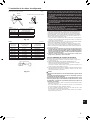
1. Safety precautions
► Before installing the unit, make sure you read all the “Safety precau-
tions”.
► Please report to or take consent by the supply authority before connec-
tion to the system.
After installation work has been completed, explain the “Safety Precautions,” use,
and maintenance of the unit to the customer according to the information in the
Operation Manual and perform the test run to ensure normal operation. Both the
Installation Manual and Operation Manual must be given to the user for keeping.
These manuals must be passed on to subsequent users.
: Indicates a part which must be grounded.
Warning:
Carefully read the labels axed to the main unit.
Warning:
Describes precautions that must be observed to prevent danger of injury or
death to the user.
Caution:
Describes precautions that must be observed to prevent damage to the unit.
This installation manual is only for the branch box installation. In installing the indoor units and outdoor units, refer to the installation manual attached to
each unit.
Warning:
• Ask a dealer or an authorized technician to install the unit.
• For installation work, follow the instructions in the Installation Manual and
use tools and pipe components specically made for use with refrigerant
specied in the outdoor unit installation manual.
• This appliance is not intended for use by persons (including children) with
reduced physical, sensory or mental capabilities, or lack of experience and
knowledge, unless they have been given supervision or instruction con-
cerning use of the appliance by a person responsible for their safety.
• Children should be supervised to ensure that they do not play with the ap-
pliance.
• The unit must be installed according to the instructions in order to mini-
mize the risk of damage from earthquakes, typhoons, or strong winds. An
incorrectly installed unit may fall down and cause damage or injuries.
• The unit must be securely installed on a structure that can sustain its
weight.
• If the air conditioner is installed in a small room, measures must be taken
to prevent the refrigerant concentration in the room from exceeding the
safety limit in the event of refrigerant leakage. Should the refrigerant leak
and cause the concentration limit to be exceeded, hazards due to lack of
oxygen in the room may result.
• Ventilate the room if refrigerant leaks during operation. If refrigerant comes
into contact with a ame, poisonous gases will be released.
• All electric work must be performed by a qualied technician according to
local regulations and the instructions given in this manual.
• Use only specied cables for wiring.
• The terminal block cover panel of the unit must be rmly attached.
• Use only authorized accessories and ask a dealer or an authorized techni-
cian to install them.
• The user should never attempt to repair the unit or transfer it to another
location.
• After installation has been completed, check for refrigerant leaks. If refrig-
erant leaks into the room and comes into contact with the ame of a heater
or portable cooking range, poisonous gases will be released.
• Be sure to connect the power supply cords and the connecting wires for
the indoor units, outdoor units, and branch boxes directly to the units (no
inter-mediate connections).
Intermediate connections can lead to communication errors if water enters
the cords or wires and causes insucient insulation to ground or a poor
electrical contact at the intermediate connection point.
(If an intermediate connection is necessary, be sure to take measures to
prevent water from entering the cords and wires.)
Caution:
• Make sure that the refrigerant pipes are well insulated to prevent condensa-
tion.
Incomplete insulation may cause condensation on the surface of pipes,
wetting of the ceiling, oor and other important properties.
• Do not use the unit in an unusual environment. If the air conditioner is
installed in areas exposed to steam, volatile oil (including machine oil), or
sulfuric gas, areas exposed to high salt content such as the seaside, the
performance can be significantly reduced and the internal parts can be
damaged.
• Do not install the unit where combustible gases may leak, be produced,
ow, or accumulate. If combustible gas accumulates around the unit, re or
explosion may result.
• When installing the unit in a hospital or communications office, be pre-
pared for noise and electronic interference. Inverters, home appliances,
high-frequency medical equipment, and radio communications equipment
can cause the air conditioner to malfunction or breakdown. The air con-
ditioner may also aect medical equipment, disturbing medical care, and
communications equipment, harming the screen display quality.
• Thermal insulation of the refrigerant pipe is necessary to prevent conden-
sation. If the refrigerant pipe is not properly insulated, condensation will be
formed.
• Place thermal insulation on the pipes to prevent condensation. If the drain-
pipe is installed incorrectly, water leakage and damage to the ceiling, oor,
furniture, or other possessions may result.
• Do not clean the air conditioner unit with water. Electric shock may result.
• Tighten all are nuts to specication using a torque wrench. If tightened
too much, the are nut can break after an extended period.
• Be sure to install circuit breakers, if not installed, electric shock may result.
• For the power lines, use standard cables of sucient capacity. Otherwise,
a short circuit, overheating, or re may result.
• When installing the power lines, do not apply tension to the cables. If the
connections are loosened, the cables can snap or break and overheating or
re may result.
• Do not connect the ground wire to gas or water pipes, lighting rods, or tele-
phone grounding lines. If the unit is not properly grounded, electric shock
may result.
• Do not turn o the breaker of M-NET Branch Box when installing the unit
below -4°F, otherwise it may result in communication failure.
• Follow the instructions below to prevent abrasive components contained in
sandpaper and cutting tools from entering the refrigerant circuit because
those components can cause failures of the compressor and valves.
- To deburr pipes, use a reamer or other deburring tools, not sandpaper.
- To cut pipes, use a pipe cutter, not a grinder or other tools that use abrasive
materials.
- When cutting or deburring pipes, do not allow cutting chips or other foreign
matters to enter the pipes.
- Ifcuttingchipsorotherforeignmattersenterpipes,wipethemotheinsideof
the pipes.
1. Safety precautions ................................................1
2. Selecting a location for installation ...................................2
3.Conrmingsuppliedaccessories .....................................2
4. Dimensions and required servicing space of Branch Box .................. 3
5. Refrigerant piping ................................................6
6. Mounting the Branch Box ..........................................7
7. Installing refrigerant piping .........................................8
8. Electrical work ..................................................10
9. Test run .......................................................14
en
1
WG79B826H01_01en.indd 1 2023/01/13 13:42:39
002

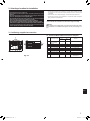
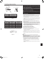
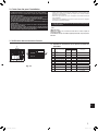
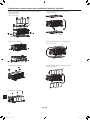
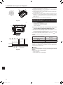
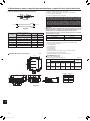
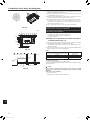
3. Conrming supplied accessories
3.1. Check the Branch Box accessories and parts
No. Accessory name Q’ty
Remarks
PAC-
MKA53BC PAC-
MKA33BC
1Washer
(with insulation) 44
2Washer 44
3Pipe cover (Liquid) 1 1 To outdoor unit
4Pipe cover (Gas) 1 1 To outdoor unit
5Pipe cover (Liquid) 5 3 To indoor units
6Pipe cover (Gas) 5 3 To indoor units
7Joint cover (Liquid) 3 1
8Joint cover (Gas) 3 1
9Band 24 16
0Conduit plate 11
Fastened to the main body
and shipped.
Fig. 3-1
29
8
5 6
4 371
2. Selecting a location for installation
* The branch box is only for indoor use.
Please attach the special optional cover to install the branch box in the
outdoors.
• Ensure that the branch box is installed above the ceiling of corridor, bath
room, etc., where persons are not regularly there.
Do not install near bed rooms, living rooms, etc. The sound of refrigerant
owing through the piping may sometimes be audible.
Also, do not install where maintenance cannot be carried out.
• Ensure that it is located where noise in operation will not be a problem.
After power is supplied or after an operation stop for a while, a small clicking
noise may be heard from the inside of the branch box. The linear expansion
valve is opening and closing. The unit is not faulty.
• Ensure that the branch box is installed in a location which facilitates servicing
and maintenance. (ensure that the required maintenance hole or service space
is available).
• Determine the route of refrigerant piping, and electrical wiring beforehand.
• Ensure that the location of the installation is such that the length of refrigerant
pipingiswithinthespeciedlimits.
* Ensure that the unit is installed in a location able to support its weight.
Warning:
Ensure that the unit is installed rmly in a location able to support its weight.
If the installation is of insucient strength the unit may fall, resulting in in-
jury.
• Do not install in location that is hot or humid for long periods of time.
en
2
WG79B826H01_01en.indd 2 2023/01/13 13:42:39
003

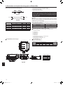
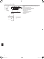
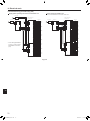
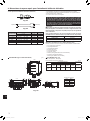
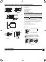
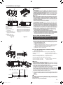
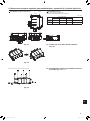
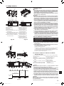
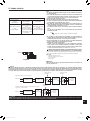
4. Dimensions and required servicing space of Branch Box
PAC-MKA53BC (5-branches type) (in)
Optional dierent-diameter (deformed) joints
Fig. 4-1
* Please connect 2 indoor units or more with 1 system.
* Up to 2 branch boxes may be connected to 1 outdoor unit.
* Suspension bolt : W3/8 (M10)
* Refrigerantpipearedconnection
* The piping connection size diers according to the type and capacity of
indoor units. Match the piping connection size for indoor unit and branch
box. If the piping connection size of branch box does not match the
piping connection size of indoor unit, use optional dierent-diameter (de-
formed) joints to the branch box side. (Connect deformed joint directly to
the branch box side.)
Caution:
Be sure to use the insulation of specified thickness. Excessive thickness
may cause incorrect installation of the indoor unit and branch box, and lack
of thickness may cause dew drippage.
2-branch pipe (Joint) : Optional parts (According to the connection method,
you can choose the favorite one.)
Model name Connection method
MSDD-50AR-E flare
MSDD-50BR-E brazing
Installation procedure (2 branch pipe (Joint))
Refer to the installation manuals of MSDD-50AR-E and MSDD-50BR-E.
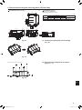
A Suspension bolt pitch
B To indoor unit
C To outdoor unit
D Service panel
E Electric cover
F Conduit plate
G Terminal block (to indoor unit on Controller board)
H Terminal block (to outdoor unit)
J Terminal block (for comunication cable)
PAC-MKA53BC (Fig. 4-3)
Suspension bolt: W3/8 (M10)
Refrigerantpipearedconnection
To indoor unit
To outdoor unit
ABCDE
Liquid pipe
1/4, ø6.35 1/4, ø6.35 1/4, ø6.35 1/4, ø6.35 1/4, ø6.35 3/8, ø9.52
Gas pipe
3/8, ø9.52 3/8, ø9.52 3/8, ø9.52 3/8, ø9.52 1/2, ø12.7 5/8, ø15.88
Model name Connected pipes diameter Diameter A Diameter B
in,
mm
in,
mm
in,
mm
MAC-A454JP-E 3/8, ø9.52 →1/2,ø12.7 3/8, ø9.52 1/2, ø12.7
MAC-A455JP-E 1/2, ø12.7 →3/8,ø9.52 1/2, ø12.7 3/8, ø9.52
MAC-A456JP-E 1/2, ø12.7 →5/8,ø15.88 1/2, ø12.7 5/8, ø15.88
PAC-493PI 1/4, ø6.35 →3/8,ø9.52 1/4, ø6.35 3/8, ø9.52
PAC-SG76RJ-E 3/8, ø9.52 →5/8,ø15.88 3/8, ø9.52 5/8, ø15.88
PAC-SG75RJ-E 5/8,ø15.88→3/4,ø19.05 5/8, ø15.88 3/4, ø19.05
D
C
E
F
H
G
J
A
B
A
EDCBA
EDCBA
15-13/16
12-19/32
1/2
1
2-9/16
2-3/4
1
1 1 11
2-3/4 2-3/4 2-3/4
2-27/32
3-17/3217-23/32
6-11/16
2-9/16 1-27/32
3-9/32 3-7/16 2-3/4
3-25/32 11-1/32 1-17/32
4-3/8
Fig. 4-3
Conversion formula
1/4 F ø6.35
3/8 F ø9.52
1/2 F ø12.7
5/8 F ø15.88
3/4 F ø19.05
A B
Fig. 4-2
B (inside)
A (outside)
in, mm
en
3
WG79B826H01_01en.indd 3 2023/01/13 13:42:40
004

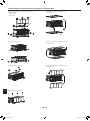
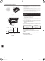
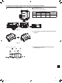
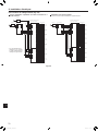
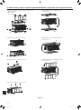
4. Dimensions and required servicing space of Branch Box
PAC-MKA33BC (3-branches type) PAC-MKA33BC (Fig. 4-4)
Suspension bolt: W3/8 (M10)
Refrigerantpipearedconnection
in, mm
To indoor unit
To outdoor unit
A B C
Liquid pipe
1/4, ø6.35 1/4, ø6.35 1/4, ø6.35 3/8, ø9.52
Gas pipe
3/8, ø9.52 3/8, ø9.52 3/8, ø9.52 5/8, ø15.88
A
A
G
H
E
FJ
CB A
CBA
D
B
C
15-13/16
12-19/32
1/2
1
8-7/32
2-3/4
111
2-3/4
2-27/32
3-17/32
17-23/32
6-11/16
2-9/16 1-27/32
3-9/32 3-7/16 2-3/4
3-25/32 11-1/32 1-17/32
4-3/8
Fig. 4-4 4.1. The direction of the piping can be changed
(Fig. 4-5)
Fig. 4-5
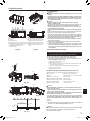
1 Remove the screws in each part. 4.2. Piping direction change work procedures
(Fig. 4-6 1~8)
(in)
Fig. 4-6
en
4
WG79B826H01_01en.indd 4 2023/01/13 13:42:41
005

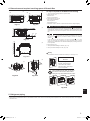
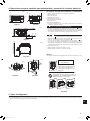
4 Fasten the screws in each part.
6 Fasten the screws in each part.
8 Fasten the screws in each part.
5 Install the service panel on the opposite surface.
B Service panel
B
7 Install the electric cover on the opposite surface.
A Electric cover
A
Fig. 4-6
4. Dimensions and required servicing space of Branch Box
2 Remove the electric cover, service panel, and top panel.
A Electric cover
B Service panel
C Top panel
B
A
C
3 Install the top panel on the opposite surface.
C Top panel
C
en
5
WG79B826H01_01en.indd 5 2023/01/13 13:42:47
006

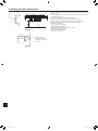
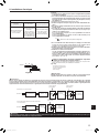
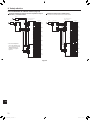
4.3. Space required for installation and servicing
1. The space when installing with the suspension bolts.
(1) Front View (Fig. 4-7)
A Branch box
B On the side of piping
(2) Side View (Fig. 4-8, Fig. 4-9)
C For indoor installations
D Ceiling board
E Maintenance hole
*1:
Minimum 13-3/4 in (350 mm) is required for 90° bends in refrigerant piping.
*2: is “ Min. 7-7/8 in (200 mm)” <recommendation>.
In the case of less than 7-7/8 in (200 mm) (for example is 4 in (100 mm)), the
exchangeworkofBranchboxfromamaintenanceholebecomesdicult(Only
exchange work of a PCB, linear expansion valve coils and sensors are possi-
ble).
In the case of “ 17-3/4 in (450 mm)”, prepare a maintenance hole at a PCB
side (as it is shown in Fig. 4-9), and “Min. 11-13/16 in (300 mm)” is needed as
distance .
In the case of less than 11-13/16 in (300 mm) (for example is 4 in (100
mm)), the exchange work of Branch box, linear expansion valve coils and
sensorsfromamaintenanceholebecomesdicult(Onlyexchangeworkofa
PCB is possible).
(3) Top View (Fig. 4-10)
2.Thespacewheninstallingontheoor.(Fig.4-11)
3. The space when installing on a wall. (Fig. 4-12)
Warning:
The installation direction is limited when installing on a wall. (Fig. 4-13)
*3: is “ 23 - 5/8 in (600 mm)” <recommendation>.
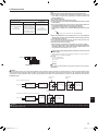
5. Refrigerant piping
* Alwaysfollowthespecicationswrittenintheinstallationmanualoftheoutdoorunit.Exceedingtheserequirementsmaycausereducedperformanceoftheequipment,
and malfunctions.
(3)
Fig. 4-10
(1) (2)
A
C
B
D E
*1
*3
*2
E D
Fig. 4-7 Fig. 4-8
Fig. 4-9
4. Dimensions and required servicing space of Branch Box
Fig. 4-11
Fig. 4-13
Fig. 4-12
(in)(in)
(in)
(in)
(in)
(in)
Correct installation
direction
When installing the unit on
the wall, install the piping
connected to the outdoor
unit facing down. Other ways
are not acceptable.
When installing on the wall, do not place
the device in the manner shown below.
Doingsomaycauseelectricshockorre.
en
6
WG79B826H01_01en.indd 6 2023/01/13 13:42:49
007

6. Mounting the Branch Box
(1)Installthesuspensionbolts(procurelocally)atthespeciedpitch(Fig.4-3,4-4).
(2) Fit the washers (1, 2) and nuts (procure locally) to the suspension bolts.
(Fig. 6-1)
(3) Hang the unit on the suspension bolts.
(4) Fully tighten the nuts (check ceiling height).
(5) Use a level to adjust the branch box to the horizontal.
A When unit is hung and nuts tightened
B Suspension bolt
C Nut (procure locally)
D Washer (with cushion) 1
E Ensure that cushion faces downwards
F Washer (without cushion) 2
G Nut (procure locally)
H Ceiling board
B
H
C
F
A
G
D(E)
B
Fig. 6-1
(in)
Fig. 6-2
* Purchase an appropriate
bracket locally if the unit
is to be mounted on a
wall.
Min. 1-3/16
Min. 2
Min. 2
Bracket
Wall
en
7
WG79B826H01_01en.indd 7 2023/01/13 13:42:49
008

7. Installing refrigerant piping
Table 1 (mm (in))
Copper pipe O.D. Flare dimensions
øA dimensions
ø6.35 (1/4) 8.7-9.1 (11/32-23/64)
ø9.52 (3/8) 12.8-13.2 (1/2-33/64)
ø12.7 (1/2) 16.2-16.6 (41/64-21/32)
ø15.88 (5/8) 19.3-19.7 (49/64-25/32)
(in) ► Connect the liquid and gas pipes of each indoor unit to the same end
connection numbers as indicated on the indoor unit flare connection
section of each Branch Box. If connected to wrong end connection
numbers, it doesn’t work normally.
► When connecting indoor units, make sure to connect refrigerant pipes
and connection wires to the appropriate connection ports marked with
matching alphabets. (Ex. A, B, C, D, E) If connected to wrong end con-
nection numbers, it doesn't work normally.
Note:
Be sure to mark all the local refrigerant piping (liquid pipes, gas pipes, etc.)
for each indoor unit designating clearly which room it belongs in. (Ex. A, B,
C, D, E)
► List indoor unit model names in the name plate of Branch Box (for iden-
tification purposes).
• Conductsucientanti-condensationandinsulationworktopreventwaterdrip-
ping from the refrigerant piping. (liquid pipe/gas pipe)
• Increase insulation depending on the environment where the refrigerant piping is
installed, or condensation may occur on the surface of the insulation material.
(Insulation material Heat-resistant temperature: 120 °C [248 °F], Thickness:
15 mm [19/32 in] or more)
* When the refrigerant piping is used in locations subject to high temperature
and humidity such as in the attic, further addition of insulation may be re-
quired.
• Insulate the liquid and gas pipes of the branch box by attaching the heat-resis-
tant polyethylene foam tightly around them. (Fig. 7-3)
Otherwise, a burn during pipe connection work or water leakage due to con-
densation on pipes may result. If connected to wrong end connection numbers,
it doesn't work normally.
► When using commercially available refrigerant piping, ensure that both
liquid and gas piping are wrapped with commercially available thermal
insulation materials (insulation materials at least 1/2 in (12 mm) thick
and able to withstand temperatures in excess of 100ºC [212°F]).
► Refer to the installation manual of the outdoor unit when creating a
vacuum and opening or closing valves.
7.1. Piping connection procedure
(1)Removethearednutsandcapsfromthebranchbox.
(2) Flare the end of the liquid and gas pipes as shown in Fig. 7-1.
(3)Applyrefrigerantoilonthearedseat.(Fig.7-2)
Usethearenutremovedfromthebranchbox.Useofano-the-shelfnut
may lead to a crack in the nut.
Forconnection,rstalignthecenter,thentightentherst3to4turnsofare
nut by hand.
(4)Connecttherefrigerantpipingimmediately.Alwaystightenthearednutsto
thetorquespeciedintheTable2usingatorquewrenchanddoublespan-
ner.
Fig. 7-1
Table 2 (mm (in))
Copper pipe O.D.
(mm (in)) Flare nut O.D.
(mm (in)) Tightening torque
(N•m (ft•lbs))
ø6.35 (1/4) 17 (43/64) 14-18 (10-13)
ø6.35 (1/4) 22 (7/8) 34-42 (25-30)
ø9.52 (3/8) 22 (7/8) 34-42 (25-30)
ø9.52 (3/8) 26 (1-3/64) 49-61 (35-44)
ø12.7 (1/2) 26 (1-3/64) 49-61 (35-44)
ø12.7 (1/2) 29 (1-9/64) 68-82 (49-59)
ø15.88 (5/8) 29 (1-9/64) 68-82 (49-59)
ø15.88 (5/8) 36 (1-27/64) 100-120 (71-87)
Flare cutting dimensions
Caution:
• Tighten the are nut with a torque wrench in the specied method.
Overtightening will cause the are nut to crack and it will cause refrigerant
leakage over a period of time.
• Follow the instructions below to prevent abrasive components contained in
sandpaper and cutting tools from entering the refrigerant circuit because
those components can cause failures of the compressor and valves.
- To deburr pipes, use a reamer or other deburring tools, not sandpaper.
- To cut pipes, use a pipe cutter, not a grinder or other tools that use abrasive
materials.
- When cutting or deburring pipes, do not allow cutting chips or other foreign
matters to enter the pipes.
- Ifcuttingchipsorotherforeignmattersenterpipes,wipethemotheinsideof
the pipes.
øA
45°±2°
R1/64 to R1/32
90° ± 0.5°
Flare nut tightening torque
Apply refrigerant oil
Fig. 7-2
en
8
WG79B826H01_01en.indd 8 2023/01/13 13:42:50
009

7. Installing refrigerant piping
3
6
4
5
(5) Press the pipe covers 3 and 5 on the liquid piping against the unit and wrap
to hold in place. (Fig. 7-3)
(6) Press the pipe covers 4 and 6 on the gas piping against the unit and wrap to
hold in place. (Fig. 7-3)
(7) Apply the supplied bands 9 at a position 7/16-13/16 in (10 - 20 mm) from
each end of the pipe covers (3456).
(8)Iftheindoorunitisnotconnected,tthesuppliedpipecovers(withcaps,7
and 8) to the branch box refrigerant piping connections against the unit to
prevent condensation dripping from the pipes. (Fig. 7-4)
(9) Clamp the pipe covers (78) in place with the supplied bands 9.
G
H
J
F
Note:
A special are nut (optional or attached to the indoor unit) is needed to
some indoor units.
Please refer to the installation manual of outdoor unit and indoor unit for
details.
F Band (3.1. Accessories No. 9)
G Pipe covers (3.1. Accessories No. 3456)
H Thermal insulation for refrigerant piping
J Refrigerant piping
7.2. Handling of ports that are not connected to out-
door unit (Fig. 7-4)
(1)Inordertopreventrefrigerantleaks,makesurethatthearenutsaretightened
accordingtothespeciedtorques*inTable3.
*Refrigerantmayalsoleakifthearenutsaretightenedmorethanthespeci-
edtorques.
(2) In order to prevent condensation, install the pipe covers 7 8 against the unit
and fasten them with the supplied bands 9.
Table 3
Diameters of branch box openings for
connecting indoor units (in, mm) Tightening torque
(ft•lbs, N•m)
1/4, ø6.35 8-11, 13 ± 2
3/8, ø9.52 21-24, 30 ± 2
1/2, ø12.7 35-38, 50 ± 2
► Refrigerant charge:
Refer to the installation manual of the outdoor unit.
Use only R410A refrigerant (use of other refrigerants may cause troubles).
Fig. 7-3
Fig. 7-4
Fig. 7-5
(in)
LJ
5 ft or less Support
Pipe cover
Caution:
To avoid excessive strain on the branch box, support the piping with one or
more support(s) 1.5 m [5 ft] or less from the branch box.
Refer to Fig. 7-5 as an example.
J Refrigerant piping
L Thermal insulation for refrigerant piping
9
9
8
7
7/16 to 13/16
1-3/16 to 2
en
9
WG79B826H01_01en.indd 9 2023/01/13 13:42:50
010

8. Electrical work
C
B
D
H~O
GEF
A
A
G
B
C
F
E
D
H
G
8.1. Precautions
Warning:
• Always use dedicated circuits with breakers, and at the rated
voltage.
Powersupplycircuitswithinsufcientcapacity,andbadwork-
manshipduringinstallation,mayresultinelectricshockorre.
•Never splice the cable, otherwise it may result in smoke, re,
or communication failure.
Caution:
• Be sure to establish an earth. Do not earth the unit to a utility pipe,
arrester, or telephone earth.
Incomplete earth may cause electrical shock. A high surge current from
lightning or other sources may cause damage to the air conditioner.
• Use the specied electrical wiring and ensure that it is connected prop-
erly, and that it is not under tension.
Failure to follow these requirements may result in broken wiring, heating,
or re.
• Never connect the main power source to the terminal block of the trans-
mission line. If connected, electrical parts will be burnt out.
• Wiring for control (hereinafter referred to as transmission line) shall be (5
cm or more) apart from power source wiring so that it is not inuenced
by electric noise from power source wiring. (Do not insert the transmis-
sion line and the power source wire in the same conduit.)
► Be sure to set the switches before turning on the breakers of the Branch
Box and the outdoor unit.
► When power is separately supplied to the branch box and the outdoor
unit, turn on the branch box first.
► Wiring connecting branch box and outdoor unit, and branch box and
indoor units, functions as both power supply and signal cable. Connect
this wiring in accordance with the terminal block numbers to ensure
correct polarity.
8.2. Electrical work procedure
► Connect refrigerant pipes and electrical wiring to the appropriate ports
marked with matching alphabets (Ex. A, B, C, D, E) on this unit. Incor-
rect wiring will interfere with the correct operation of the unit.
► First, connect the power supply cable from the outdoor unit.
► Always fix each ground wire separately with a ground screw.
► To prevent that wiring installed in the ceiling is chewed by rats etc., it
should be installed in wiring conduit.
(1) Remove the electric cover. (Fig. 8-1)
(2) Remove the conduit cover.
(3) Pass the wiring into the branch box through the conduit plate and fix with
the conduit plate. (Refer to 8.3.)
(4) Firmly connect each wire to the appropriate terminal block. (Fig. 8-9)
(5) Set dip sw. (Refer to 8.5.)
(6) Replace the electric cover.
8.3. When using wiring conduit (Fig. 8-5, 8-6, 8-7)
Replacetheelectriccoverwhenthewiringconduithasbeenxedinplace.
A Electric cover H Wiring conduit (For TB5B)
B Wiring J Conduit plate (3.1. Accessories No. 0)
C Nut 1/2” (procure locally) K Conduit hole
D Wiring conduit (For TB3A, TB3B) L Conduit pipe
E Wiring conduit (For TB3C, TB3D) M Controller board
F Wiring conduit (For TB3E) N 2-branch wiring conduit
(procure locally)
G Wiring conduit (For TB2B)
Caution:
• When installing the conduit plate J, cut out only the knockout holes that
are necessary for wiring B.
Cutting out unnecessary knockout holes may cause damage due to the in-
vasion of small creatures and the like.
• When cutting out the knockout holes on the conduit plate, beware that nei-
ther deformation nor distortion occurs on the plate.
Also, when installing the conduit plate, beware that no gap exists between
the plate and the conduit pipes or the conduit holes, otherwise it may cause
failure of the controller board due to the invasion of small creatures or in-
sects.
(Fig. 8-6)
► To divide the wirings of each terminal block into 2 branches outside the
branch box, use 2-branch wiring conduits N. (Fig. 8-7)
Caution:
To avoid excessive strain on the branch box, support the conduit pipe L with
one or more support(s) 1.5 m [5 ft] or less from the branch box.
Refer to Fig. 8-8 as an example.
N
Fig. 8-7Fig. 8-6
M
L
J
K
Fig. 8-5
Fig. 8-1 Fig. 8-2
Fig. 8-3 Fig. 8-4
L
Fig. 8-8
A Electric cover
B Conduit plate
C Wiring
D Controller board
E
Terminal block:
TB5 <Transmission line>
F
Terminal block: TB2B <For Power Supply /
To outdoor unitor other branch box>
G Terminal block: TB3A-TB3E
<To indoor unit>
H Earth Terminal <Power supply>
J Earth Terminal <To indoor unit A>
K Earth Terminal <To indoor unit B>
L Earth Terminal <To indoor unit C>
M Earth Terminal <To indoor unit D>
N Earth Terminal <To indoor unit E>
O Earth Terminal <To other branch
box>
Support
5 ft or less
en
10
WG79B826H01_01en.indd 10 2023/01/13 13:42:52
011

8. Electrical work
Supply power separately to branch box and outdoor unit Power supply from Outdoor unit
* Refer to be installation manual of the outdoor unit
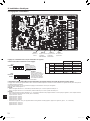
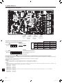
8.4. External wiring procedure (Fig. 8-9)
Fig. 8-9
(C)
TB3A
(C)
TB3A
(C)
TB3B
(C)
TB3C
(C)
TB3B
(C)
TB3C
(C)
TB3D
(C)
TB3E
(A) TB2B
TB5
(B)
TB5
(A) TB2B
~
~
(B)
S1
S2
S3
S1
S2
S3
S1
S2
S3
S1
S2
S3
S1
S2
S3
S1
S2
S3
S1
S2
S3
S1
S2
S3
S1
S2
S3
S1
S2
S3
S1
S2
S3
S1
S2
S3
S1
S2
S3
S1
S2
S3
S1
S2
S3
S1
S2
S3
L2
L1
GR
B1
B2
M1
M2
L1
L2
L1
L2
M1
M2
S
M1
M2
S
Circuit breaker
Outdoor unit Indoor unit
Indoor
unit A
Pull box
Indoor
unit F
Indoor
unit B
Indoor
unit G
Indoor
unit C
Indoor
unit H
Indoor
unit D
Indoor
unit E
M-NET Branch BOX #1
(5-branches type)
Circuit breaker
Indoor unit
M-NET Branch BOX #2
(3-branches type)
Pull box
(C)
TB3A
(C)
TB3B
(C)
TB3C
(C)
TB3D
(C)
TB3E
(C)
TB3A
(C)
TB3B
(C)
TB3C
TB5
TB2B
TB2B
TB5
(A)
(B)
(B)
(A)
~L1
L2
GR
B1
B2
M1
M2
L1
L2
M1
M2
L1
L2
M1
M2
S1
S2
S3
S1
S2
S3
S1
S2
S3
S1
S2
S3
S1
S2
S3
S1
S2
S3
S1
S2
S3
S1
S2
S3
S1
S2
S3
S1
S2
S3
S1
S2
S3
S1
S2
S3
S1
S2
S3
S1
S2
S3
S1
S2
S3
S1
S2
S3
S
S
Outdoor unit
Indoor
unit A
Indoor
unit F
Indoor
unit B
Indoor
unit G
Indoor
unit C
Indoor
unit H
Indoor
unit D
Indoor
unit E
M-NET Branch BOX #1
(5-branches type)
Circuit breaker
M-NET Branch BOX #2
(3-branches type)
Indoor unit
Indoor unit
* Forthewiringspecications
of (A) to (C), refer to “Wiring
Specications”onthenext
page.
en
11
WG79B826H01_01en.indd 11 2023/01/13 13:42:52
012

Warning:
Never splice the cable, otherwise it may result in a smoke, a re or communi-
cation failure.
Note:
1 Wiring size must comply with the applicable local and national code.
2 Power supply cords and indoor unit/branch box/outdoor unit connecting
cords shall not be lighter than polychloroprene sheathed flexible cord.
(Design 60245 IEC 57)
3 Use copper supply wires.
4 Install an earth line longer than the power cables.
5 Connect the wiring in accordance with the terminal block names to ensure
correct polarity.
6 Indoor unit and branch box connecting wires(C) have polarities. Make sure
to match the terminal number (S1, S2, S3) for correct wirings.
As for lines (C), S1 and S2 are for connecting the power source.
S2 and S3 are for signals. S2 is a common cable for the power source and
signal.
7 When using twisted wire for the wiring, the use of a round terminal is
required. Take care when using strand wires, because fraying wires may
cause the wiring to short out.
8 Do not bundle the M-NET cable with the connection cable and power sup-
ply cable. It may cause erroneous operation.
9 Recommended connection methods:
When connecting one indoor unit to the branch box, connect it to TB3A.
When connecting 2 indoor units, connect them to TB3A and TB3B. When
connecting 3 indoor units, connect them to TB3A, TB3B, and TB3C. Con-
nect indoor units in the order of A→B→C→D→E.
WiringSpecications
(A) Main power line/
Earth line (B) M-NETcable (C) Signal line/
Earth line
Use UL wires rated 300 V
or more
2.1 mm2 (AWG14)
Shielded wire
Use UL wire rated 300 V
1.25 mm2 (AWG16)
Less than 200 m [656 ft]
Connect the shielded part
of the shielded wire to the
S terminal on TB5.
Use UL wires rated 300 V
or more
1.25 mm2 (AWG16)
Less than 25 m [82 ft]
L1
L2
L1
L2
L1
L2 B1
B2
L1
L2
S1
S2
S3
S1
S2
S3
L1
L2
L1
L2
S1
S2
S3
S1
S2
S3
L1
L2
Caution:
After using the isolator, be sure to turn off and on the main power supply to reset the system. Otherwise, the outdoor unit may not be able to detect the
branch box(es) or indoor units.
Warning:
In case of A-control wiring, there is high voltage potential on the S3 terminal caused by electrical circuit design that has no electrical insulation between power
line and communication signal line. Therefore, please turn o the main power supply when servicing. And do not touch the S1, S2, S3 terminals when the power
is energized. If an isolator should be used, use the 2 pole type between the outdoor unit and the branch box, and use the 3 pole type between the branch box
and the indoor unit.
8. Electrical work
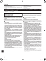
Power supply wiring (Supply power separately to branch box and
outdoor unit)
• A switch with at least 3 mm, 1/8 inch contact separation in each pole shall be
provided by the air conditioner installation.
[Fig. 8-10]
A
Ground-fault interrupter
B
Local switch/Wiring breaker
C
Branch Box
D
Pull box
D
CTB2B TB5
S
M1
L1 L2 M2
AB
208/230V
Fig. 8-10
* Power supply from outdoor unit
* Supply power separately to branch box and outdoor unit
Power supply
Power supply
Isolator (Switch)
Isolator (Switch)
Outdoor unit
2 pole isolator
(Switch)
3 pole isolator
(Switch)
3 pole isolator
(Switch)
Branch box
Branch box
"A-control
Indoor unit"
"A-control
Indoor unit"
S1
S3 Assign S1 and S3 to the cores placed diagonally.
en
12
WG79B826H01_01en.indd 12 2023/01/13 13:42:53
013

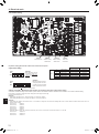
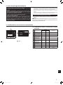
8.5. Switch setting
8. Electrical work
Dip switch setting (Shut o the outdoor unit and branch box power
supply before setting)
123456
ON
OFF
SW1
123456
ON
OFF
SW4
7 8 9 10
OFF ON
SW1
1 Indoor unit A Not connected Connected
2 Indoor unit B Not connected Connected
3 Indoor unit C Not connected Connected
4 Indoor unit D Not connected Connected
5 Indoor unit E Not connected Connected
6 Not used
Address switch SW11, SW12 (Shut o the outdoor unit and branch box power supply before setting)
Actualindoorunitaddresssettingvariesindierentsystems.Refertotheinstallationmanualfortheoutdoorunitfordetailsonhowtomaketheaddresssetting.
Each address is set with a combination of the settings for the tens digit and ones digit.
[Factory default value] Set to “1”.
(Example)
• When setting the address to “3”, SW12 (tens digit) “0”, SW11 (ones digit) “3”
• When setting the address to “25”, SW12 (tens digit) “2”, SW11 (ones digit) “5”
(Example)
• When setting the address of the branch box to “3”, an address is assigned to each indoor unit starting with Unit A as shown below no matter if each indoor unit is con-
nected. (SW1-1~5 ON)
Indoor Unit A Address 3
Indoor Unit B Address 4
Indoor Unit C Address 5
Indoor Unit D Address 6
Indoor Unit E Address 7
• When the address is set to “25” and also 3 indoor units (Unit A, Unit C, and Unit E) are connected. (SW1-1, 1-3, 1-5 ON)
Indoor Unit A Address 25
Indoor Unit C Address 26
Indoor Unit E Address 27
(Example)
• When the indoor units are
connected to Indoor unit
A and C, turn SW1-1 and
SW1-3 to on.
SW12
Address setting
TENS DIGIT
SW11
Address setting
ONES DIGIT
SW1
Indoor unit
connections
1234567890
SW4
ON
OFF
(Example)
• When the system includes a
cooling only indoor unit, turn
on SW4-5 of all the controller
boards on the Branch boxes.
The black square ( ) indicates a switch position.
SW4
Model selection
en
13
WG79B826H01_01en.indd 13 2023/01/13 13:42:53
014

9. Test run
• Refer to the “Test run” section of the installation manual of the indoor units and outdoor unit.
• Whenthebranchboxandoutdoorpowersourceareseparate,turnonthepowerofthebranchboxrst,andthenturnontheoutdoorunitpower.
• After power is supplied or after an operation stop for a while, a small clicking noise may be heard from the inside of the branch box. The linear expansion
valve is opening and closing. The unit is not faulty.
• Be sure to perform the test run in cooling mode for each indoor unit. Make sure each indoor unit operates properly following the installation manual attached to the unit.
• If you perform the test run for all indoor units at once, you cannot detect any erroneous connection, if any, of the refrigerant pipes and the indoor/outdoor unit connecting
wires.
• To check for improper wiring, perform the test run for each indoor unit individually.
Caution:
• Use the remote controller to operate the indoor unit.
• The following symptoms are not malfunctions.
Symptom Cause Indoor unit LED display *
Indoor unit does not operate even if set to
cooling (heating) operation The cooling (heating) operation cannot be operated when the heating (cooling)
operation of another indoor unit is operating. Stand by (For Multi System)
Indoor unit fan stops during heating operation The fan stops during defrosting operation. -
Fan stops when the refrigerant collecting mode ** is activated. Stand by (For Multi System)
dda
* See the operation manual of indoor units for details.
**Thismodeisactivatedforapproximately1minutetohelpavoidaninsucientsupplyofrefrigerantduringheatingoperationwhenrefrigerantisstoredinanindoorunit
thathasbeenturnedoorthermo-o.
en
14
WG79B826H01_01en.indd 14 2023/01/13 13:42:53
015

Index
1. Consignes de sécurité
► Avant d’installer le climatiseur, lisez attentivement toutes les “Consignes
de sécurité”.
► Veuillez consulter ou obtenir la permission de votre compagnie d’électri-
cité avant de connecter votre système.
Une fois l’installation terminée, expliquez les “Consignes de sécurité”, l’utilisation et
l’entretien de l’appareil au client conformément aux informations du mode d’emploi
et eectuez la marche d’essai pour garantir un fonctionnement normal. Le manuel
d’installation et le mode d’emploi doivent être fournis à l’utilisateur qui doit les conser-
ver. Ces manuels doivent également être transmis aux nouveaux utilisateurs.
: Indique un élément qui doit être mis à la terre.
Avertissement :
Prenez soin de lire les étiquettes se trouvant sur l’appareil principal.
Avertissement :
Précautions à suivre pour éviter tout danger de blessure ou de décès de
l’utilisateur.
Précaution :
Décrit les précautions qui doivent être prises pour éviter d’endommager
l’appareil.
Ce manuel d’installation n’est dédié qu’à l’installation du boîtier de dérivation. Pour l’installation des appareils intérieurs et extérieurs, reportez-vous au manuel
d’installation propre à chaque appareil.
Avertissement :
• Contactez un revendeur ou un technicien agréé pour installer l’appareil.
• Pour l’installation, respectez les instructions du manuel d’installation et
utilisez des outils et des composants de tuyau spécialement conçus pour
une utilisation avec le réfrigérant spécié dans le manuel d’installation de
l’appareil extérieur.
• Cet appareil n’est pas conçu pour être utilisé par des personnes (y compris
des enfants) présentant des capacités physiques, sensorielles ou mentales
réduites, ou manquant d’expérience et de connaissances, à moins qu’elles
ne soient supervisées ou aient reçu des instructions relatives à l’utilisation
de l’appareil par une personne responsable de leur sécurité.
• Les enfants doivent être surveillés pour s’assurer qu’ils ne jouent pas avec
l’appareil.
• L’appareil doit être installé conformément aux instructions pour réduire
les risques de dommages liés à des tremblements de terre, des typhons ou
des vents violents. Une installation incorrecte peut entraîner la chute de
l’appareil et provoquer des dommages ou des blessures.
• L’appareil doit être solidement installé sur une structure pouvant supporter
son poids.
• Si le climatiseur est installé dans une petite pièce, certaines mesures doivent
être prises pour éviter que la concentration de réfrigérant ne dépasse le seuil
de sécurité en cas de fuite. En cas de fuite de réfrigérant et de dépassement
du seuil de concentration, des risques liés au manque d’oxygène dans la pièce
peuvent survenir.
•
Aérez la pièce en cas de fuite de réfrigérant lors de l’utilisation. Le contact du
réfrigérant avec une amme peut provoquer des émanations de gaz toxiques.
• Tout travail sur les installations électriques doit être eectué par un techni-
cien qualié conformément aux réglementations locales et aux instructions
fournies dans ce manuel.
• N’utilisez que les câbles spéciés pour les raccordements.
• Le couvercle du bornier de l’appareil doit être solidement xé.
• N’utilisez que les accessoires agréés et contactez un revendeur ou un tech-
nicien agréé pour les installer.
• L’utilisateur ne doit jamais essayer de réparer ou de déplacer l’appareil.
• Une fois l’installation terminée, vériez les éventuelles fuites de réfrigérant.
Si le réfrigérant fuit dans la pièce et entre en contact avec la amme d’un
chauage ou d’une cuisinière, des gaz toxiques peuvent se dégager.
• Veillez à relier les cordons d’alimentation et les ls de raccordement des
appareils intérieurs, des appareils extérieurs et des boîtiers de dérivation
directement sur les appareils (sans raccordement intermédiaire).
Les raccordements intermédiaires peuvent engendrer des erreurs de com-
munication si de l’eau s’inltre dans les cordons et les ls et entraînent une
isolation insusante de la mise à la terre ou un mauvais contact électrique
au niveau du point de raccordement intermédiaire.
(Si un raccordement intermédiaire est nécessaire, veillez à prendre des
mesures an d’éviter que l’eau ne pénètre dans les cordons et les ls.)
Précaution :
• Vériez que les tuyaux de réfrigérant sont bien isolés pour empêcher la for-
mation de condensation.
Une isolation incomplète peut provoquer de la condensation à la surface
des tuyaux, l’apparition d’humidité au niveau du plafond et du sol, ainsi
qu’à d’autres situations sérieuses.
• N’utilisez pas l’appareil dans un environnement inhabituel. Si le climatiseur est
installé dans des endroits exposés à la vapeur, à l’huile volatile (notamment
l’huile de machine), au gaz sulfurique ou à une forte teneur en sel, par exemple,
en bord de mer, les performances peuvent considérablement diminuer et les
pièces internes de l’appareil être endommagées.
• N’installez pas l’appareil dans des endroits où des gaz de combustion peuvent
s’échapper, se dégager ou s’accumuler. L’accumulation de gaz de combustion
autour de l’appareil peut provoquer un incendie ou une explosion.
• Lors de l’installation de l’appareil dans un hôpital ou un centre de commu-
nications, préparez-vous au bruit et aux interférences électroniques. Les
inverseurs, les appareils électroménagers, les équipements médicaux haute
fréquence et de communications radio peuvent provoquer un dysfonction-
nement ou une défaillance du climatiseur. Le climatiseur peut également
endommager les équipements médicaux et de communications, perturbant
ainsi les soins et réduisant la qualité d’achage des écrans.
•
Isolez le tuyau de réfrigérant pour éviter la condensation. S’il n’est pas correc-
tement isolé, de la condensation risque de se former.
• Placez un isolant thermique sur les tuyaux pour éviter la condensation.
L’installation incorrecte du tuyau d’écoulement peut provoquer des fuites
d’eau et endommager le plafond, le sol, les meubles ou d’autres objets.
•
Ne nettoyez pas le climatiseur à l’eau au risque de provoquer un choc électrique.
• Serrez tous les écrous évasés conformément aux spécications à l’aide
d’une clé dynamométrique. S’ils sont trop serrés, ils peuvent casser après
une période prolongée.
•
Veillez à installer des coupe-circuits. Sinon, une électrocution pourrait en résulter.
•
Pour les lignes d’alimentation, utilisez des câbles standard de capacité susante.
Sinon, un court-circuit, une surchaue ou un incendie pourraient en résulter.
• Lors de l’installation des lignes d’alimentation, ne mettez pas les câbles sous
tension. Si les raccordements sont lâches, les câbles peuvent se rompre ou
surchauer et entraîner un incendie.
•
Ne raccordez pas les câbles de mise à la terre aux tuyaux du gaz ou de l’eau, aux
poteaux d’éclairage ou aux lignes de mise à la terre du téléphone. Si l’appareil
n’est pas mis à la terre correctement, des électrocutions pourraient en résulter.
• Ne mettez pas hors tension le disjoncteur du boîtier de dérivation M-NET lors
de l'installation de l'appareil par une température inférieure à -20 °C (-4 °F),
sinon, une panne de communication pourrait en résulter.
• Suivez les instructions ci-dessous pour éviter que les composants abrasifs
contenus dans le papier de verre et les outils de coupe ne pénètrent dans
le circuit de réfrigérant, car ces composants peuvent provoquer des défail-
lances du compresseur et des vannes.
- Pour ébavurer les tuyaux, utilisez un alésoir ou d’autres outils d’ébavurage, et
non du papier de verre.
- Pour couper les tuyaux, utilisez un coupe-tuyaux et non une meuleuse ou
d’autres outils qui utilisent des matériaux abrasifs.
- Lors de la coupe ou de l’ébavurage des tuyaux, ne laissez pas des copeaux
de métal ou d’autres matières étrangères pénétrer dans les tuyaux.
- Si des copeaux de métal ou d’autres matières étrangères pénètrent dans les
tuyaux, éliminez-les de l’intérieur des tuyaux.
1. Consignes de sécurité ............................................. 1
2. Choix d’un site pour l’installation ..................................... 2
3. Vérication des accessoires fournis .................................. 2
4. Dimensions et espace requis pour l’entretien du boîtier de dérivation ........ 3
5. Tuyau de réfrigérant .............................................. 6
6. Montage du boîtier de dérivation ..................................... 7
7. Installation des tuyaux de réfrigérant. . . . . . . . . . . . . . . . . . . . . . . . . . . . . . . . . . 8
8. Installations électriques ........................................... 10
9. Marche d’essai ................................................. 14
1
fr
016

2. Choix d’un site pour l’installation
* Le boîtier de dérivation est conçu uniquement pour un usage à l’intérieur.
Veuillez xer le couvercle spécial fourni en option pour installer le boîtier
de dérivation à l’extérieur.
•
Vériez que le boîtier de dérivation est installé au-dessus du plafond du couloir,
de la salle de bain, etc. c’est-à-dire dans un endroit peu fréquenté.
Ne pas installer à proximité de chambres, salons, etc. Le son du réfrigérant
s’écoulant dans la tuyauterie est parfois audible.
En outre, ne procédez pas à l’installation dans un endroit où la maintenance
est impossible.
• Vériez qu’il est placé dans un endroit où le bruit en fonctionnement ne
représente pas un problème.
Une fois sous tension ou après un arrêt prolongé, un cliquetis provenant
de l’intérieur du boîtier de dérivation se fait entendre. Le détendeur linéaire
s’ouvre et se ferme. L’appareil n’est pas défectueux.
• Vériez que le boîtier de dérivation est installé dans un endroit pratique pour
l’entretien et la maintenance. (Vériez que l’espace ou les orices d’entretien
nécessaires sont accessibles.)
• Déterminez l’agencement des tuyaux de réfrigérant et des câbles électriques
avant l’installation.
• Vériez que le site d’installation est tel que la longueur des tuyaux de réfrigérant
ne dépasse pas les limites spéciées.
* Vériez que l’appareil est installé dans un endroit capable de supporter son
poids.
Avertissement :
Vériez que l’appareil est correctement installé dans un endroit capable de
supporter son poids.
Si l’installation manque de solidité, l’appareil peut tomber et provoquer des
blessures.
• Ne procédez pas à l’installation dans un endroit chaud ou humide pendant
de longues périodes.
3. Vérication des accessoires fournis
3.1. Vériez les accessoires et les pièces du boîtier de
dérivation
N° Nom des accessoires Qté
Remarques
PAC-
MKA53BC PAC-
MKA33BC
1Rondelle
(isolée) 44
2Rondelle 44
3Cache-tuyaux (liquide) 11Vers l’appareil extérieur
4Cache-tuyaux (gaz) 11Vers l’appareil extérieur
5Cache-tuyaux (liquide) 53Vers l’appareil intérieur
6Cache-tuyaux (gaz) 53Vers l’appareil intérieur
7Couvre-joint (liquide) 31
8Couvre-joint (gaz) 31
9Sangle 24 16
0Plaque de conduit 1 1 Fixé sur le corps principal
et expédié.
Fig. 3-1
29
8
5 6
4 371
2
fr
017

4. Dimensions et espace requis pour l’entretien du boîtier de dérivation
Joints optionnels de diérents diamètres (déformés)
Fig. 4-1
* Il est possible de raccorder au moins 2 appareils intérieurs à 1 système.
* Vous pouvez raccorder jusqu’à 2 boîtiers de dérivation sur 1 appareil extérieur.
* Boulon de suspension : W3/8 (M10)
* Raccord évasé des tuyaux de réfrigérant
* La taille des raccordements de tuyau dière selon le type et la capacité
des appareils intérieurs. Adaptez la taille du raccordement du tuyau de
l’appareil intérieur et du boîtier de dérivation. Si la taille du raccordement
du tuyau du boîtier de dérivation dière de celle du raccordement du tuyau
de l’appareil intérieur, utilisez des joints (déformés) d’un diamètre diérent
(disponibles en option) au niveau du boîtier de dérivation. (Raccordez le joint
déformé directement au niveau du boîtier de dérivation.)
A B
Précaution :
Veiller à utiliser l’isolation de l’épaisseur indiquée. Une épaisseur trop impor-
tante peut engendrer une installation incorrecte de l’appareil intérieur et du
boîtier de dérivation ; une épaisseur trop faible peut provoquer un égouttement
de la condensation.
Tuyau à 2 embranchements (Joint) : Pièces disponibles en option (en fonction
de la méthode de raccordement choisie, il est possible de choisir votre préférée).
Nom de modèle Méthode de raccordement
MSDD-50AR-E évasement
MSDD-50BR-E brasage
■Procédure d’installation (tuyau à 2 embranchements (Joint))
Veuillez consulter les manuels d’installation des MSDD-50AR-E et MSDD-50BR-E.
A Pas du boulon de suspension
B Vers l’appareil intérieur
C Vers l’appareil extérieur
D Panneau de service
E Couverture électrique
F Plaque de conduit
G Bornier (vers appareil intérieur sur carte contrôleur)
H H Bornier (vers appareil extérieur)
J Bornier (pour câble de communication)
PAC-MKA53BC (Fig. 4-3)
Boulon de suspension : W3/8 (M10)
Raccord évasé des tuyaux de réfrigérant
Vers l’appareil intérieur
Vers l’appareil
extérieur
ABCDE
Tuyau de
liquide
1/4, ø6,35 1/4, ø6,35 1/4, ø6,35 1/4, ø6,35 1/4, ø6,35 3/8, ø9,52
Tuyau de
gaz
3/8, ø9,52 3/8, ø9,52 3/8, ø9,52 3/8, ø9,52 1/2, ø12,7 5/8, ø15,88
B (intérieur)
A (extérieur)
Nom du modèle Diamètre des tuyaux raccordés Diamètre A Diamètre B
po, mm po, mm po, mm
MAC-A454JP-E 3/8, ø9,52 → 1/2, ø12,7 3/8, ø9,52 1/2, ø12,7
MAC-A455JP-E 1/2, ø12,7 → 3/8, ø9,52 1/2, ø12,7 3/8, ø9,52
MAC-A456JP-E 1/2, ø12,7 → 5/8, ø15,88 1/2, ø12,7 5/8, ø15,88
PAC-493PI 1/4, ø6,35 → 3/8, ø9,52 1/4, ø6,35 3/8, ø9,52
PAC-SG76RJ-E 3/8, ø9,52 → 5/8, ø15,88 3/8, ø9,52 5/8, ø15,88
PAC-SG75RJ-E 5/8, ø15,88 → 3/4, ø19,05 5/8, ø15,88 3/4, ø19,05
D
C
E
F
H
G
J
A
B
A
EDCBA
EDCBA
15-13/16
12-19/32
1/2
1
2-9/16
2-3/4
1
1 1 11
2-3/4 2-3/4 2-3/4
2-27/32
3-17/3217-23/32
6-11/16
2-9/16 1-27/32
3-9/32 3-7/16 2-3/4
3-25/32 11-1/32 1-17/32
4-3/8
PAC-MKA53BC (type à 5 embranchements) (po)
Fig. 4-3
Formule de conversion
1/4 F ø6,35
3/8 F ø9,52
1/2 F ø12,7
5/8 F ø15,88
3/4 F ø19,05
po, mm
Fig. 4-2
3
fr
018

4. Dimensions et espace requis pour l’entretien du boîtier de dérivation
PAC-MKA33BC (type à 3 embranchements) PAC-MKA33BC (Fig. 4-4)
Boulon de suspension : W3/8 (M10)
Raccord évasé des tuyaux de réfrigérant po, mm
Vers l’appareil intérieur
Vers l’appareil
extérieur
ABC
Tuyau de
liquide
1/4, ø6,35 1/4, ø6,35 1/4, ø6,35 3/8, ø9,52
Tuyau de
gaz
3/8, ø9,52 3/8, ø9,52 3/8, ø9,52 5/8, ø15,88
Fig. 4-4
4.1. Il est possible de modier la direction des tuyaux
(Fig. 4-5)
Fig. 4-5
1 Retirer les vis de chaque pièce. 4.2. Procédures de changement de direction des
tuyaux (Fig. 4-6 1~8)
(po)
Fig. 4-6
A
A
G
H
E
FJ
CB A
CBA
D
B
C
15-13/16
12-19/32
1/2
1
8-7/32
2-3/4
111
2-3/4
2-27/32
3-17/32
17-23/32
6-11/16
2-9/16 1-27/32
3-9/32 3-7/16 2-3/4
3-25/32 11-1/32 1-17/32
4-3/8
4
fr
019

4 Fixez les vis de chaque pièce.
6 Fixez les vis de chaque pièce.
8 Fixez les vis de chaque pièce.
5 Installez le panneau de service sur la surface opposée.
B Panneau de service
B
7 Installez la protection électrique sur la surface opposée.
A Protection électrique
A
Fig. 4-6
4. Dimensions et espace requis pour l’entretien du boîtier de dérivation
2 Retirez le capot électrique, le panneau de service et le panneau supérieur.
A Protection électrique
B Panneau de service
C Panneau supérieur
B
A
C
3 Installez le panneau supérieur sur la surface opposée.
C Panneau supérieur
C
5
fr
020
La page est en cours de chargement...
La page est en cours de chargement...
La page est en cours de chargement...
La page est en cours de chargement...
La page est en cours de chargement...
La page est en cours de chargement...
La page est en cours de chargement...
La page est en cours de chargement...
La page est en cours de chargement...
La page est en cours de chargement...
La page est en cours de chargement...
La page est en cours de chargement...
La page est en cours de chargement...
La page est en cours de chargement...
La page est en cours de chargement...
La page est en cours de chargement...
La page est en cours de chargement...
La page est en cours de chargement...
La page est en cours de chargement...
La page est en cours de chargement...
La page est en cours de chargement...
La page est en cours de chargement...
La page est en cours de chargement...
La page est en cours de chargement...
-
 1
1
-
 2
2
-
 3
3
-
 4
4
-
 5
5
-
 6
6
-
 7
7
-
 8
8
-
 9
9
-
 10
10
-
 11
11
-
 12
12
-
 13
13
-
 14
14
-
 15
15
-
 16
16
-
 17
17
-
 18
18
-
 19
19
-
 20
20
-
 21
21
-
 22
22
-
 23
23
-
 24
24
-
 25
25
-
 26
26
-
 27
27
-
 28
28
-
 29
29
-
 30
30
-
 31
31
-
 32
32
-
 33
33
-
 34
34
-
 35
35
-
 36
36
-
 37
37
-
 38
38
-
 39
39
-
 40
40
-
 41
41
-
 42
42
-
 43
43
-
 44
44


Mitsubishi Electric PAC-MKA53BC Manuel utilisateur
- Catégorie
- Climatiseurs split-system
- Taper
- Manuel utilisateur