
GB
F
Air-Conditioners For Building Application
HEAT SOURCE UNIT
PQHY-P72·96TGMU-A
INSTALLATION MANUAL
For safe and correct use, please read this installation manual thoroughly before installing the air-conditioner unit.
MANUEL D’INSTALLATION
Veuillez lire le manuel d’installation en entier avant d’installer ce climatiseur pour éviter tout accident et vous assurer d’une utilisation correcte.
For use with R410A

2
5
[Fig. 5.0.1]
8 m
[26 ft]
=
>
8 m
[26 ft]
=
>
40°
=
<
B
A
C
990 [39]
900 [35-7/16]
45
[1-25/32]
550 [21-21/32]
570 [22-15/32]
16
[21/32]
602 [23-23/32]
D
E
A
B
C
D
600
[23-5/8]
550
[21-21/32]
400
[15-3/4] 990 [39]
990 [39]
400
[15-3/4]
400
[15-3/4]
F
G
H
E
E
D
H
G
F
C
B
A
TB8
3
A
B
4
63PW
[Fig. 6.1.1]
[Fig. 7.4.1]
[Fig. 7.1.1]
7.1
7.4
[Fig. 6.1.2]
[Fig. 6.2.1]
6.2
[Fig. 6.2.2]
A Heat source unit
B 4-ø14 [9/16] (Anchoring hole)
C (Top view)
A Piping space (for side piping)
B Heat source unit
C Service space (front side)
D (Top view)
D Anti-vibration pad etc.
E Concrete base
E Piping space (for top piping)
F Piping space (for side piping)
G Heat source unit
H (Front view)
A Water circulation pipe
B Close valve
C Close valve
D Water outlet
A Short-circuit wire (Connected before delivery from manufacturer)
B Pump interlock circuit connection
6.1
6
7
E
D
H
G
F
C
B
A
E Refrigerant piping
F Y-type strainer
G Water inlet
H Drain pipe
Side piping
Top piping

3
8
8.2
[Fig. 8.2.1]
A Heat source unit
B First branch
C Indoor unit
D Cap
B
A
A
B C D
e
a
1
b c d
234
5
C
C
CCC
B
A
a
b
1
2
c d e
345
C
D
CC
CC
A
A (Unit: mm [in])
Å Heat source model
P72
P96
ı Liquid pipe
ø9.52 [3/8]
* ø9.52 [3/8]
Ç Gas pipe
ø19.05 [3/4]
ø22.2 [7/8]
* ø12.7 [1/2] for over 90m [295 ft]
B, C, D (Unit: mm [in])
Î Total capacity of indoor units
~ 54
55 ~ 72
73 ~
ı Liquid pipe
ø9.52 [3/8]
ø9.52 [3/8]
ø9.52 [3/8]
Ç Gas pipe
ø15.88 [5/8]
ø19.05 [3/4]
ø22.2 [7/8]
a, b, c, d, e (Unit: mm [in])
‰ Model number
06,08,12,15,18
24,27,30,36,48,54
72
96
ı Liquid pipe
ø6.35 [1/4]
ø9.52 [3/8]
ø9.52 [3/8]
ø9.52 [3/8]
Ç Gas pipe
ø12.7[1/2]
ø15.88 [5/8]
ø19.05 [3/4]
ø22.2 [7/8]
Ó 4-Branching header
(Downstream unit
model total
<
=
200)
CMY-Y104-G
¬ 8-Branching header
(Downstream unit
model total
<
=
400)
CMY-Y108-G
Ô
10-Branching header
(Downstream unit
model total
<
=
650)
CMY-Y1010-G
Ï Downstream unit model total
~ 72
73 ~ 400
Ì Branch kit model
CMY-Y102S-G
CMY-Y102L-G
[Fig. 9.2.2]
9.2
9
[Fig. 9.2.1]
A
B
1
3
<A> [Ball valve (Low press. side/flanged type)] <B> [Ball valve (High press. side/flared type)]
[Fig. 9.2.3]
A Close-packed packing
B Hollow packing
<C> This figure shows the valve
in the fully open state.
A Valve stem
B Stopper pin
C Packing (Accessory)
D Connecting pipe (Accessory)
E Open (Operate slowly)
F Cap
G Service port
H Flare nut
I ø9.52 [3/8] (PQHY-P72)
ø9.52 [3/8] (PQHY-P96)
J ø19.05 [3/4] (PQHY-P72)
ø22.2 [7/8] (PQHY-P96)
K Field piping
I
E
OS
SO
K
J
H
G
F
E
D
C
B
A

4
10
[Fig. 9.4.4]
[Fig. 9.4.3][Fig. 9.4.2]
C
A
B
D
E
[Fig. 9.4.1]
[Fig. 10.2.1]
B
A
D
C
E
E
E
D
A
B
D
F
G
B
<D> Floor (waterproofing)
E
I
B
<C> Outer wall (exposed)
A B
<A> Inner wall (concealed)
A B
D
C
<B> Outer wall
F
H
D
B
G
<E> Roof pipe shaft
I
A
J
1m1m
[3.28 ft][3.28 ft]
<F> Penetrating portion on fire
limit and boundary wall
10.2
AB
C
L1 L2 L3 M1M2 M1M2 S
TB3 TB7
TB1
A Steel wire B Piping
C Asphaltic oily mastic or asphalt
D Heat insulation material A
E Outer covering B
A Liquid pipe B Gas pipe
C Electric wire D Finishing tape
E Insulator
A : Sleeve B : Heat insulating material
C : Lagging D : Caulking material
E : Band F : Waterproofing laye
G : Sleeve with edge H : Lagging material
I : Mortar or other incombustible caulking
J : Incombustible heat insulation material
A : Power source
B : Transmission line
C : Ground screw
D
C
C
B
B
E
F
G
H
I
J
A
LO
HI
LO
HI
B
A
K
J
L
H
M
C
D
EN
O
F
G
I
[Fig. 9.3.1]
[Fig. 9.3.3]
[Fig. 9.3.2]
9.3
A
A Nitrogen gas
B To indoor unit
C System analyzer
D Lo knob
E Hi knob
F Ball valve
G Liquid pipe
H Gas pipe
I Heat source unit
J Service port
A System analyzer
B Lo knob
C Hi knob
D Ball valve
E Liquid pipe
F Gas pipe
G Service port
H Three-way joint
I Valve
J Valve
K R410A cylinder
L Scale
M Vacuum pump
N To indoor unit
O Heat source unit
A : Syphon pipe
B In case of the cylinder having no syphon pipe.
9.4

5
A B C
E
D
M1 M2
M1 M2 S
TB7
TB3
IC
(51)
M1 M2 S
TB5
RC
(01)
IC
M1 M2 S
TB5
(02)
IC
M1 M2 S
TB5
(04)
IC
M1 M2 S
TB5
(03)
IC
M1 M2 S
TB5
(05)
IC
M1 M2 S
TB5
(07)
IC
M1 M2 S
TB5
(06)
L2
L1
(101)
RC
(105)
RC
(103)
RC
(155)
OC
M1 M2
M1 M2 S
TB7
TB3
CN40
(52)
OC
r3
M1M2S
System
controller
L3
L6
L4
L5
r2
r4
r1
AB AB AB
AB
CN40
A B C
E
D
M1 M2
M1 M2 S
TB7
TB3
IC
(51)
M1 M2 12S
TB5 TB15
12
TB15
12
TB15
12
TB15
12
TB 15
12
TB15
MA
(01)
IC
M1 M2 S
TB5
(02)
IC
M1 M2 S
TB5
(04)
IC
M1 M2 S
TB5
(03)
IC
M1 M2 S
TB5
(05)
IC
M1 M2 S
TB5
(07)
IC
M1 M2 S
TB5
(06)
L2
L1
MA
MA
MA
OC
M1 M2
M1 M2 S
TB7
TB3
(52)
OC
c1
c4
S
System
controller
L3
L6
L4
c2
AB
AB
AB
AB
M1M2
c2
c1
c1
c2
CN40
CN40
c3
10.3
BA
C
~208–230 V
BA
~208–230 V
E E
D
E E
[Fig. 10.3.2]
[Fig. 10.3.1]
A : Group 1
B : Group 3
C : Group 5
D : Shielded wire
E : Sub remote
controller
( ) Address
<A> Change the jumper connec-
tor from CN41 to CN40
<B> SW2-1:ON
<C> Keep the jumper connector
on CN41
<B> SW2-1:ON
<A> Change the jumper connec-
tor from CN41 to CN40
<B> SW2-1:ON
<C> Keep the jumper connector
on CN41
<B> SW2-1:ON
[Fig. 10.4.1]
A : Switch (breakers for wiring and current leakage)
B : Breakers for current leakage
C : Heat source unit
D : Pull box
E : Indoor unit
10.4

6
GB
D
FINL EPGRRUTR
Contents
1. Safety precautions
1.1. Before installation and electric work
s Before installing the unit, make sure you read all the “Safety
precautions”.
s The “Safety precautions” provide very important points re-
garding safety. Make sure you follow them.
Symbols used in the text
Warning:
Describes precautions that should be observed to prevent danger of injury
or death to the user.
Caution:
Describes precautions that should be observed to prevent damage to the
unit.
Symbols used in the illustrations
: Indicates an action that must be avoided.
: Indicates that important instructions must be followed.
: Indicates a part which must be grounded.
: Beware of electric shock. (This symbol is displayed on the main unit label.)
<Color: yellow>
Warning:
Carefully read the labels affixed to the main unit.
Warning:
• Ask the dealer or an authorized technician to install the air conditioner.
- Improper installation by the user may result in water leakage, electric shock,
or fire.
• Install the unit in a place that can withstand its weight.
- Inadequate strength may cause the unit to fall down, resulting in injuries.
• Use the specified cables for wiring. Make the connections securely so
that the outside force of the cable is not applied to the terminals.
- Inadequate connection and fastening may generate heat and cause a fire.
• Prepare for rain and other moisture and earthquakes and install the unit
at the specified place.
- Improper installation may cause the unit to topple over and result in injury.
• Always use an filter and other accessories specified by Mitsubishi Elec-
tric.
- Ask an authorized technician to install the accessories. Improper installation
by the user may result in water leakage, electric shock, or fire.
• Never repair the unit. If the air conditioner must be repaired, consult the
dealer.
- If the unit is repaired improperly, water leakage, electric shock, or fire may
result.
• If refrigerant gas leaks during installation work, ventilate the room.
- If the refrigerant gas comes into contact with a flame, poisonous gases will
be released.
• Install the air conditioner according to this Installation Manual.
- If the unit is installed improperly, water leakage, electric shock, or fire may
result.
• Have all electric work done by a licensed electrician according to “Elec-
tric Facility Engineering Standard” and “Interior Wire Regulations”and
the instructions given in this manual and always use a special circuit.
- If the power source capacity is inadequate or electric work is performed im-
properly, electric shock and fire may result.
• Securely install the heat source unit terminal cover (panel).
- If the terminal cover (panel) is not installed properly, dust or water may enter
the heat source unit and fire or electric shock may result.
• When installing and moving the air conditioner to another site, do not
charge it with a refrigerant different from the refrigerant (R410A) speci-
fied on the unit.
- If a different refrigerant or air is mixed with the original refrigerant, the refrig-
erant cycle may malfunction and the unit may be damaged.
• If the air conditioner is installed in a small room, measures must be taken
to prevent the refrigerant concentration from exceeding the safety limit
even if the refrigerant should leak.
- Consult the dealer regarding the appropriate measures to prevent the safety
limit from being exceeded. Should the refrigerant leak and cause the safety
limit to be exceeded, hazards due to lack of oxygen in the room could result.
• When moving and reinstalling the air conditioner, consult the dealer or
an authorized technician.
- If the air conditioner is installed improperly, water leakage, electric shock, or
fire may result.
• After completing installation work, make sure that refrigerant gas is not
leaking.
- If the refrigerant gas leaks and is exposed to a fan heater, stove, oven, or
other heat source, it may generate noxious gases.
• Do not reconstruct or change the settings of the protection devices.
- If the pressure switch, thermal switch, or other protection device is shorted
and operated forcibly, or parts other than those specified by Mitsubishi Elec-
tric are used, fire or explosion may result.
• To dispose of this product, consult your dealer.
• The installer and system specialist shall secure safety against leakage
according to local regulation or standards.
- Following standards may be applicable if local regulation are not available.
• Pay a special attention to the place, such as a basement, etc. where re-
frigeration gas can stay, since refrigeration is heavier than the air.
1.2. Precautions for devices that use R410A
refrigerant
Caution:
• Do not use the existing refrigerant piping.
- The old refrigerant and refrigerator oil in the existing piping contains a large
amount of chlorine which may cause the refrigerator oil of the new unit to
deteriorate.
- R410A is a high-pressure refrigerant and can cause the existing piping to
burst.
• Use refrigerant piping made of phosphorus deoxidized copper and cop-
per alloy seamless pipes and tubes. In addition, be sure that the inner
and outer surfaces of the pipes are clean and free of hazardous sulphur,
oxides, dust/dirt, shaving particles, oils, moisture, or any other contami-
nant.
- Contaminants on the inside of the refrigerant piping may cause the refriger-
ant residual oil to deteriorate.
• Store the piping to be used during installation indoors and keep both
ends of the piping sealed until just before brazing. (Store elbows and
other joints in a plastic bag.)
- If dust, dirt, or water enters the refrigerant cycle, deterioration of the oil and
compressor trouble may result.
• Use ester oil, ether oil or alkylbenzene (small amount) as the refrigerator
oil to coat flares and flange connections.
- The refrigerator oil will degrade if it is mixed with a large amount of mineral
oil.
1. Safety precautions ...................................................................................... 6
1.1. Before installation and electric work .......................................... 6
1.2. Precautions for devices that use R410A refrigerant .................. 6
1.3. Before getting installed .............................................................. 7
1.4. Before installation electrical work .............................................. 7
1.5. Before starting the test run ........................................................ 7
2. About the product ....................................................................................... 7
3. Specifications .............................................................................................. 7
4. Confirmation of parts attached ................................................................... 8
5. Lifting method ............................................................................................. 8
6. Installation of unit and service space .......................................................... 8
6.1. Installation ................................................................................. 8
6.2. Service space ............................................................................ 8
7. Water pipe installation ................................................................................. 8
7.1. Precautions during installation .................................................. 8
7.2. Insulation installation ................................................................. 8
7.3. Water processing and water quality control ............................... 8
7.4. Pump interlock........................................................................... 9
8. Refrigerant piping installation ..................................................................... 9
8.1. Caution ...................................................................................... 9
8.2. Refrigerant piping system .......................................................... 9
9. Additional refrigerant charge ..................................................................... 10
9.1. Calculation of additional refrigerant charge ............................. 10
9.2. Precautions concerning piping connection and
valve operation ........................................................................ 10
9.3. Airtight test, evacuation, and refrigerant charging ................... 11
9.4. Thermal insulation of refrigerant piping ................................... 11
10. Wiring ........................................................................................................ 12
10.1. Caution .................................................................................... 12
10.2. Control box and connecting position of wiring ......................... 12
10.3. Wiring transmission cables ...................................................... 12
10.4. Wiring of main power supply and equipment capacity ............ 14
11. Test run ..................................................................................................... 14
11.1. The following phenomena do not represent trouble
(emergency) ............................................................................ 14
12.Information on rating plate ......................................................................... 14

7
GB
D
FINL EPGRRUTR
• The reverse phase of L lines (L1, L2, L3) can be detected (Error cord: 4103),
but the reverse phase of L lines and N line can be not be detected.
- The some electric parts should be damaged when power is supplied under
the miss wiring.
• Install the power cable so that tension is not applied to the cable.
- Tension may cause the cable to break and generate heat and cause a fire.
• Install a leak circuit breaker, as required.
- If a leak circuit breaker is not installed, electric shock may result.
• Use power line cables of sufficient current carrying capacity and rating.
- Cables that are too small may leak, generate heat, and cause a fire.
• Use only a circuit breaker and fuse of the specified capacity.
- A fuse or circuit breaker of a larger capacity or a steel or copper wire may
result in a general unit failure or fire.
• Do not wash the air conditioner units.
- Washing them may cause an electric shock.
• Be careful that the installation base is not damaged by long use.
- If the damage is left uncorrected, the unit may fall and cause personal injury
or property damage.
• Install the drain piping according to this Installation Manual to ensure
proper drainage. Wrap thermal insulation around the pipes to prevent
condensation.
- Improper drain piping may cause water leakage and damage to furniture
and other possessions.
• Be very careful about product transportation.
- Only one person should not carry the product if it weighs more than 20 kg
[45 LBS].
- Some products use PP bands for packaging. Do not use any PP bands for a
means of transportation. It is dangerous.
- When transporting the heat source unit, support it at the specified positions
on the unit base. Also support the heat source unit at four points so that it
cannot slip side ways.
• Safely dispose of the packing materials.
- Packing materials, such as nails and other metal or wooden parts, may cause
stabs or other injuries.
- Tear apart and throw away plastic packaging bags so that children will not
play with them. If children play with a plastic bag which was not torn apart,
they face the risk of suffocation.
1.5. Before starting the test run
Caution:
• Turn on the power at least 12 hours before starting operation.
- Starting operation immediately after turning on the main power switch can
result in severe damage to internal parts. Keep the power switch turned on
during the operational season.
• Do not touch the switches with wet fingers.
- Touching a switch with wet fingers can cause electric shock.
• Do not touch the refrigerant pipes during and immediately after operation.
- During and immediately after operation, the refrigerant pipes are may be hot
and may be cold, depending on the condition of the refrigerant flowing through
the refrigerant piping, compressor, and other refrigerant cycle parts. Your
hands may suffer burns or frostbite if you touch the refrigerant pipes.
• Do not operate the air conditioner with the panels and guards removed.
- Rotating, hot, or high-voltage parts can cause injuries.
• Do not turn off the power immediately after stopping operation.
- Always wait at least five minutes before turning off the power. Otherwise,
water leakage and trouble may occur.
• Do not touch the surface of the compressor during servicing.
- If unit is connected to the supply and not running, crank case heater at
compressor is operating.
• Use liquid refrigerant to fill the system.
- If gas refrigerant is used to seal the system, the composition of the refriger-
ant in the cylinder will change and performance may drop.
• Do not use a refrigerant other than R410A.
- If another refrigerant (R22, etc.) is mixed with R410A, the chlorine in the
refrigerant may cause the refrigerator oil to deteriorate.
• Use a vacuum pump with a reverse flow check valve.
- The vacuum pump oil may flow back into the refrigerant cycle and cause the
refrigerator oil to deteriorate.
• Do not use the following tools that are used with conventional refriger-
ants.
(Gauge manifold, charge hose, gas leak detector, reverse flow check valve,
refrigerant charge base, refrigerant recovery equipment)
- If the conventional refrigerant and refrigerator oil are mixed in the R410A,
the refrigerant may deteriorated.
- If water is mixed in the R410A, the refrigerator oil may deteriorate.
- Since R410A does not contain any chlorine, gas leak detectors for conven-
tional refrigerants will not react to it.
• Do not use a charging cylinder.
- Using a charging cylinder may cause the refrigerant to deteriorate.
• Be especially careful when managing the tools.
- If dust, dirt, or water gets in the refrigerant cycle, the refrigerant may deteriorate.
1.3. Before getting installed
Caution:
• Do not install the unit where combustible gas may leak.
- If the gas leaks and accumulates around the unit, an explosion may result.
• Do not use the air conditioner where food, pets, plants, precision instru-
ments, or artwork are kept.
- The quality of the food, etc. may deteriorate.
• Do not use the air conditioner in special environments.
- Oil, steam, sulfuric smoke, etc. can significantly reduce the performance of
the air conditioner or damage its parts.
• When installing the unit in a hospital, communication station, or similar
place, provide sufficient protection against noise.
- The inverter equipment, private power generator, high-frequency medical
equipment, or radio communication equipment may cause the air conditioner
to operate erroneously, or fail to operate. On the other hand, the air condi-
tioner may affect such equipment by creating noise that disturbs medical
treatment or image broadcasting.
• Do not install the unit on a structure that may cause leakage.
- When the room humidity exceeds 80 % or when the drain pipe is clogged,
condensation may drip from the indoor unit. Perform collective drainage work
together with the heat source unit, as required.
1.4. Before installation electrical work
Warning
When installing or relocating the unit, make sure that no substance other
than the specified refrigerant (R410A) enters the refrigerant circuit.
Any presence of foreign substance such as air can cause abnormal pres-
sure rise or explosion.
Caution:
• Ground the unit.
- Do not connect the ground wire to gas or water pipes, lightning rods, or
telephone ground lines. Improper grounding may result in electric shock.
3. Specifications
Model
Noise level
Net weight
Allowable pressure
Refrigerant
Indoor units
Total capacity
Model / Quantity
Operation temperature
Maximum water pressure
Rated water volume
Allowable water volume
PQHY-P72TGMU-A PQHY-P96TGMU-A
46 dB <A> 47 dB <A>
266 kg [588 LBS] 269 kg [594 LBS]
HP: 4.15 MPa [601 psi], LP: 2.21 MPa [320 psi]
R410A: 7.0 kg [15 LBS 7 oz] R410A: 8.0 kg [17 LBS 11 oz]
50 ~ 130 %
P06 ~ P96 / 1 ~ 13 P06 ~ P96 / 1 ~ 16
Water temperature: 10˚C ~ 45˚C [50˚F ~ 113˚F]
1.0 MPa [145 psi]
4.56 m
3
/h [1204 G/h] 5.76 m
3
/h [1521 G/h]
3.9 ~ 6.8 m
3
/h [1030 ~ 1795 G/h] 4.5 ~ 7.2 m
3
/h [1181 ~ 1901 G/h]
2. About the product
• This unit uses R410A-type refrigerant
• Piping for systems using R410A may be different from that for systems using
conventional refrigerant because the design pressure in systems using R410A
is higher. Refer to Data Book for more information.
• Some of the tools and equipment used for installation with systems that use
other types of refrigerant cannot be used with the systems using R410A. Refer
to Data Book for more information.
• Do not use the existing piping, as it contains chlorine, which is found in con-
ventional refrigerating machine oil and refrigerant. This chlorine will deteriorate
the refrigerant machine oil in the new equipment. The existing piping must not
be used as the design pressure in systems using R410A is higher than that in
the systems using other types of refrigerant and the existing pipes may burst.

8
GB
D
FINL EPGRRUTR
6. Installation of unit and service space
6.1. Installation
• Using the anchoring holes shown below, firmly bolt the unit to the base.
[Fig. 6.1.1] (P.2)
A Heat source unit B 4-ø14 [9/16] (Anchoring hole)
C (Top view)
Bases and anti-vibration
• Be sure to install unit in a place strong enough to withstand its weight. If the
base is unstable, reinforce with a concrete base.
• The unit must be anchored on a level surface. Use a level to check after
installation.
• Anti-vibration pads must be placed under the base of the unit.
• If the unit is installed near a room where noise is a problem, using an anti-
vibration stand on the base of the unit is recommended.
[Fig. 6.1.2] (P.2)
D Anti-vibration pad etc. E Concrete base
Warning:
• Be sure to install unit in a place strong enough to withstand its weight.
Any lack of strength may cause unit to fall down, resulting in a personal
injury.
• Have installation work in order to protect against earthquake.
Any installation deficiency may cause unit to fall down, resulting in a
personal injury.
6.2. Service space
• Please allow for the following service spaces after installation.
(All servicing can be performed from the front of the unit)
[Fig. 6.2.1] (P.2)
A Piping space (for side piping) B Heat source unit
C Service space (front side) D (Top view)
[Fig. 6.2.2] (P.2)
E Piping space (for top piping) F Piping space (for side piping)
G Heat source unit H (Front view)
5. Lifting method
[Fig. 5.0.1] (P.2)
Caution:
Be very careful when carrying the product.
- Do not have only one person to carry product if it is more than 20 kg [46 LBS].
- PP bands are used to pack some products. Do not use them as a mean for transportation because they are dangerous.
- Tear plastic packaging bag and scrap it so that children cannot play with it. Otherwise plastic packaging bag may suffocate children to death.
- When carrying the heat source unit, be sure to support it at four points. Carrying with 3-point support may make the heat source unit unstable, resulting in it falling.
4. Confirmation of parts attached
1 Connecting pipe × 1 (Connecting pipe is fixed with the unit.) 2 Packing (inside ø23 [29/32 in], outside ø35 [1-13/32 in]) × 1
3 Bushing × 2
7. Water pipe installation
• City Multi WY Series pipes are similar to other air-conditioning pipes, however,
please observe the following precautions during installation.
7.1. Precautions during installation
• Use the reverse-return method to insure proper pipe resistance to each unit.
• To insure easy maintenance, inspection, and replacement of the unit, use a
proper joint, valve, etc. on the water intake and outlet port. In addition, be sure
to install a strainer on the water intake pipe. (In order to maintain the heat
source unit, a strainer on the circulating water inlet is necessary.)
* An example of the heat source unit installation is shown in the diagram be-
low.
• Install a suitable air vent on the water pipe. After sending water through the
pipe, be sure to vent the excess air.
• Compressed water may form in the low-temperature sections of heat source
unit. Use a drainage pipe connected to the drain valve at the base of the unit to
drain the water.
• There is a water vent plug in the center of the heat exchanger water inlet head
at the middle of the unit. Use this for maintenance, etc.
In addition, do not allow any of the unit’s electrical parts (such as the solenoid
valve coil or compressor power supply) to become wet.
• Install a back flow-prevention valve on the pump and a flexible joint to prevent
excess vibration.
• Use a sleeve to protect the pipes where they go through a wall.
• Use metal fittings to secure the pipes, and install them so that they have maxi-
mum protection against breakage and bending.
• Do not confuse the water intake and outlet valves.
• This unit doesn’t have any heater to prevent freezing within tubes. When the
water flow is stopped on low ambient, take out the water from tubes.
• The unused knockout holes should be closed and the opening of refrigerant
pipes, water pipes, power source and transmission wires should be filled with
putty and so on to prevent from rain. (field construction)
Example of heat source unit installation (using left piping)
[Fig. 7.1.1] (P.2)
A Water circulation pipe B Close valve
C Close valve D Water outlet
E Refrigerant piping F Y-type strainer
G Water inlet H Drain pipe
7.2. Insulation installation
With City Multi WY Series piping, as long as the temperature range of the circulat-
ing water is kept to average temperatures year-round (30 °C [86 °F] in the summer,
20 °C [68 °F] in the winter), there is no need to insulate or otherwise protect indoor
piping from exposure. You should use insulation in the following situations:
• Any heat source piping.
• Indoor piping in cold-weather regions where frozen pipes are a problem.
• When air coming from the outside causes condensation to form on piping.
• Any drainage piping.
7.3. Water processing and water quality con-
trol
To preserve water quality, use the closed type of cooling tower for WY. When the
circulating water quality is poor, the water heat exchanger can develop scales,
leading to a reduction in heat-exchange power and possible corrosion of the heat
exchanger. Please pay careful attention to water processing and water quality control
when installing the water circulation system.
• Removal of foreign objects or impurities within the pipes.
During installation, be careful that foreign objects, such as welding fragments,
sealant particles, or rust, do not enter the pipes.
• Water Quality Processing
1 Depending on the quality of the cold-temperature water used in the air-
conditioner, the copper piping of the heat exchanger may become corroded.
We recommend regular water quality processing.
Cold water circulation systems using open heat storage tanks are
particularly prone to corrosion.
When using an open-type heat storage tank, install a water-to-water heat
exchanger, and use a closed-loop circuit on the air conditioner side. If a
water supply tank is installed, keep contact with air to a minimum, and
keep the level of dissolved oxygen in the water no higher than 1mg/r.

9
GB
D
FINL EPGRRUTR
2 Water quality standard
Reference : Guideline of Water Quality for Refrigeration and Air Conditioning
Equipment. (JRA GL02E-1994)
3 Please consult with a water quality control specialist about water quality
control methods and water quality calculations before using anti-corrosive
solutions for water quality management.
4 When replacing a previously installed air conditioning device (even when
only the heat exchanger is being replaced), first conduct a water quality
analysis and check for possible corrosion.
Corrosion can occur in cold-water systems even if there has been no prior
signs of corrosion.
If the water quality level has dropped, please adjust water quality suffi-
ciently before replacing the unit.
7.4. Pump interlock
The heat source unit may become damaged if it is operated with no water circulat-
ing through the pipes.
Be sure to interlock unit operation and the water-circuit pump. Use the terminal
blocks for interlocking (TB8-3, 4) that can be found on the unit.
In the case of a pump interlock circuit signal connection to the TB8-3, 4, remove
the short-circuit wire. Also, to prevent mistaken error detection, resulting from a
poor connection, in the pressure valve 63PW, use a low maintained current of 5mA
or less.
[Fig. 7.4.1] (P.2)
A Short-circuit wire (Connected before delivery from manufacturer)
B Pump interlock circuit connection
pH (25˚C) [77°F]
Electric conductivity
(mS/m) (25°C) [77°F]
(µ s/cm) (25°C) [77°F]
Chloride ion (mg Cl
-
/r)
Sulfate ion (mg SO4
2-
/r)
Acid consumption (pH4.8)
(mg CaCO
3
/r)
Total hardness (mg CaCO
3
/r)
Calcium hardness (mg CaCO
3
/r)
Ionic silica (mg SiO
2
/r)
Iron (mg Fe/r)
Copper (mg Cu/r)
Sulfide ion (mg S
2-
/r)
Ammonium ion (mg NH
4
+
/r)
Residual chlorine (mg Cl/r)
Free carbon dioxide (mg CO
2
/r)
Ryzner stability index
Standard
items
Refer-
ence
items
Items
Lower mid-range
temperature water system
7.0 ~ 8.0
30 or less
[300 or less]
50 or less
50 or less
50 or less
70 or less
50 or less
30 or less
1.0 or less
1.0 or less
not to be
detected
0.3 or less
0.25 or less
0.4 or less
–
7.0 ~ 8.0
30 or less
[300 or less]
50 or less
50 or less
50 or less
70 or less
50 or less
30 or less
0.3 or less
0.1 or less
not to be
detected
0.1 or less
0.3 or less
4.0 or less
–
Tendency
Recirculating
water
[20<T<60°C]
[68<T<140°F]
Make-up
water
Corrosive
Scale-
forming
8. Refrigerant piping installation
A Residues in commercially available antioxidants may have adverse effects on
the equipment. Braze only with non-oxide brazing material. The use of other
brazing material may result in compressor damage.
(Refer to item 9.2. for detailed information on pipe connections and valve op-
erations.)
B Never perform heat source unit piping connection work when it is raining.
Warning
When installing and moving the unit, do not charge it with refrigerant other
than the refrigerant specified on the unit.
- Mixing of a different refrigerant, air, etc. may cause the refrigerant cycle to mal-
function and result in severe damage.
Caution:
• Use a vacuum pump with a reverse flow check valve.
- If the vacuum pump does not have a reverse flow check valve, the vacuum
pump oil may flow back into the refrigerant cycle and cause deterioration of
the refrigerator oil and other trouble.
• Do not use the tools shown below used with conventional refrigerant.
(Gauge manifold, charge hose, gas leak detector, check valve, refrigerant
charge base, vacuum gauge, refrigerant recovery equipment)
- Mixing of conventional refrigerant and refrigerator oil may cause the refrig-
erator oil to deteriorate.
- Mixing of water will cause the refrigerator oil to deteriorate.
- R410A refrigerant does not contain any chlorine. Therefore, gas leak detec-
tors for conventional refrigerants will not react to it.
• Manage the tools more carefully than normal.
- If dust, dirt, or water gets in the refrigerant cycle, the refrigerator oil will dete-
riorate.
• Never use existing refrigerant piping.
- The large amount of chlorine in conventional refrigerant and refrigerator oil
in the existing piping will cause the new refrigerant to deteriorate.
• Store the piping to be used during installation indoors and keep both
ends of the piping sealed until just before brazing.
- If dust, dirt, or water gets into the refrigerant cycle, the oil will deteriorate and
the compressor may fail.
• Do not use a charging cylinder.
- Using a charging cylinder may cause the refrigerant to deteriorate.
• Do not use special detergents for washing piping.
8.2. Refrigerant piping system
Connection Example
[Fig. 8.2.1] (P.3)
Å Heat source model ı Liquid pipe
Ç Gas pipe Î Total capacity of indoor units
‰ Model number Ï Downstream unit model total
Ì Branch kit model
Ó 4-Branching header (Downstream unit model total
<
=
200)
¬ 8-Branching header (Downstream unit model total
<
=
400)
Ô 10-Branching header (Downstream unit model total
<
=
650)
A Heat source unit B First branch
C Indoor unit D Cap
Connecting the piping is a terminal-branch type in which refrigerant piping from
the heat source unit is branched at the terminal and connected to each of the
indoor units.
The method of pipe connection is as follows: flare connection for the indoor units, gas
pipes for heat source units, flare connection for P72 and brazed connection for P96 ~
P168; liquid pipes, flare connection. Note that the branched sections are brazed.
Warning:
Always use extreme care to prevent the refrigerant gas from leaking while
using fire or flame. If the refrigerant gas comes in contact with a flame from
any source, such as a gas stove, it breaks down and generates a poisonous
gas which can cause gas poisoning. Never weld in an unventilated room.
Always conduct an inspection for gas leakage after installation of the refrig-
erant piping has been completed.
8.1. Caution
This unit uses refrigerant R410A. Follow the local regulations on materials and
pipe thickness when selecting pipes.
1 Use the following materials for refrigeration piping.
• Material: Use refrigerant piping made of phosphorus deoxidized copper.
In addition, be sure that the inner and outer surfaces of the pipes are clean
and free of hazardous sulphur, oxides, dust/dirt, shaving particles, oils,
moisture, or any other contaminant.
2 Commercially available piping often contains dust and other materials. Always
blow it clean with a dry inert gas.
3 Use care to prevent dust, water or other contaminants from entering the piping
during installation.
4 Reduce the number of bending portions as much as possible, and make bend-
ing radius as big as possible.
5 Always observe the restrictions on the refrigerant piping (such as rated length,
the difference between high/low pressures, and piping diameter). Failure to do
so can result in equipment failure or a decline in heating/cooling performance.
6 Either a lack or an excess of refrigerant causes the unit to make an emergency
stop. Charge the system with an appropriate amount of refrigerant. At such a
time, always properly charge the unit. When servicing, always check the notes
concerning pipe length and amount of additional refrigerant at both locations,
the refrigerant volume calculation table on the back of the service panel and
the additional refrigerant section on the labels for the combined number of
indoor units.
7 Use liquid refrigerant to fill the system.
8 Never use refrigerant to perform an air purge. Always evacuate using a vacuum
pump.
9 Always insulate the piping properly. Insufficient insulation will result in a de-
cline in heating/cooling performance, water drops from condensation and other
such problems.
0 When connecting the refrigerant piping, make sure the ball valve of the heat
source unit is completely closed (the factory setting) and do not operate it until
the refrigerant piping for the heat source and indoor units has been connected,
a refrigerant leakage test has been performed and the evacuation process has
been completed.

10
GB
D
FINL EPGRRUTR
9. Additional refrigerant charge
At the time of shipping, the heat source unit is charged with the refrigerant. As this
charge does not include the amount needed for extended piping, additional charg-
ing for each refrigerant line will be required on site. In order that future servicing
may be properly provided, always keep a record of the size and length of each
refrigerant line and the amount of additional charge by writing it in the space pro-
vided on the heat source unit.
9.1. Calculation of additional refrigerant
charge
• Calculate the amount of additional charge based on the length of the piping
extension and the size of the refrigerant line.
• Use the table to the below as a guide to calculating the amount of additional
charging and charge the system accordingly.
• If the calculation results in a fraction of less than 0.1 kg [4 oz], round up to the
next 0.1 kg [4 oz]. For example, if the result of the calculation was 8.48 kg
[277.4 oz], round the result up to 8.5 kg [280 oz].
<Additional Charge>
• Flare machining dimension for systems using R410A is larger than that for
systems using other types of refrigerant in order to increase the air tightness.
• Refer to the table on the below for flare machining dimensions, and follow the
regulations set forth by the local authorities. Seal off the opening of the pipe
with a closure material (not supplied) to keep small animals from entering the
pipe if that is a concern.
flare machining dimension (mm)
[Fig. 9.2.2] (P.3)
<A> [Ball valve (Gas side/flanged type)]
<B> [Ball valve (Liquid side/flared type)]
<C> This figure shows the valve in the fully open state.
A Valve stem
[Fully closed at the factory, when connecting the piping, when evacuating, and
when charging additional refrigerant. Open fully after the operations above are
completed.]
B Stopper pin [Prevents the valve stem from turning 90° or more.]
C Packing (Accessory)
[Manufacturer: Nichiasu corporation]
[Type: T/#1991-NF]
D Connecting pipe (Accessory)
[Use packing and securely install this pipe to the valve flange so that gas leakage
will not occur. (Tightening torque:40 N·m [400kg·cm]) Coat both surfaces of the
packing with refrigerating machine oil. (Ester oil, ether oil or alkylbenzene [small
amount])]
E Open (Operate slowly)
F Cap, copper packing
[Remove the cap and operate the valve stem. Always reinstall the cap after op-
eration is completed. (Valve stem cap tightening torque: 23 ~ 27 N·m [230 ~ 270
kg·cm])]
G Service port
[Use this port to evacuate the refrigerant piping and add an additional charge at
the site.
Open and close the port using a double-ended wrench.
Always reinstall the cap after operation is completed. (Service port cap tightening
torque: 12 ~ 15 N·m [120 ~ 150 kg·cm)]
H Flare nut
[Tightening torque: Refer to the following table.
Loosen and tighten this nut using a double-ended wrench.
Coat the flare contact surface with refrigerating machine oil (Ester oil, ether oil or
alkylbenzene [small amount])]
I ø9.52 [3/8] (PQHY-P72)
ø9.52 [3/8] (PQHY-P96)
J ø19.05 [3/4] (PQHY-P72)
ø22.2 [7/8] (PQHY-P96)
K Field piping
Appropriate tightening torque by torque wrench:
Copper pipe external dia. (mm [in]) Tightening torque (N·m / kg·cm)
ø6.35 [1/4] 14 to 18 / 140 to 180
ø9.52 [3/8] 35 to 42 / 350 to 420
ø12.7 [1/2] 50 to 57.5 / 500 to 575
ø15.88 [5/8] 75 to 80 / 750 to 800
ø19.05 [3/4] 100 to 140 / 1000 to 1400
Tightening angle standard:
Pipe diameter (mm [in]) Tightening angle (°)
ø6.35 [1/4], ø9.52 [3/8] 60 to 90
ø12.7 [1/2], ø15.88 [5/8] 30 to 60
ø19.05 [3/4] 20 to 35
[Fig. 9.2.3] (P.3)
flare nut size (mm)
A
B
outer diameter
ø6.35
ø9.52
ø12.70
ø15.88
ø19.05
size in inches
1/4"
3/8"
1/2"
5/8"
3/4"
dimension A
R410A
9.1
13.2
16.6
19.7
24.0
outer diameter
ø6.35
ø9.52
ø12.70
ø15.88
ø19.05
size in inches
1/4"
3/8"
1/2"
5/8"
3/4"
dimension B
R410A
17.0
22.0
26.0
29.0
36.0
<Example>
Indoor 1: 24 A: ø9.52 [3/8] 40 m [131 ft] a: ø9.52 [3/8] 10 m [32 ft]
2: 36 B: ø9.52 [3/8] 10 m [32 ft] b: ø9.52 [3/8] 5 m [16 ft]
3: 15 C: ø9.52 [3/8] 15 m [49 ft] c: ø6.35 [1/4] 10 m [32 ft]
4: 12 D: ø9.52 [3/8] 10 m [32 ft] d: ø6.35 [1/4] 10 m [32 ft]
5: 24 e: ø9.52 [3/8] 10 m [32 ft]
The total length of each liquid line is as follows:
ø9.52 [3/8]: A + B + C + D + a + b + e = 40 [131] + 10 [32] + 15 [49] + 10 [32]
+ 10 [32] + 5 [16] + 10 [32]
= 100 m [292 ft]
ø6.35 [1/4]: c + d = 10 [32] + 10 [32] = 20 m [64 ft]
Therefore,
<Calculation example>
Additional refrigerant charge
= 100 [292] × 0.06 [0.65] + 20 [64] × 0.024 [0.26] + 2.0 [71] = 8.5 kg [280 oz]
Value of α
Total capacity of connecting indoor units α
Models 31 to 60 1.5 kg [53 oz]
Models 61 to 126 2.0 kg [71 oz]
9.2. Precautions concerning piping connec-
tion and valve operation
• Conduct piping connection and valve operation accurately.
• Flange type side connecting pipe is assembled in factory before shipment.
1 For brazing to the connecting pipe with flange, remove the connecting pipe
with flange from the ball valve, and braze it outside of the unit.
2 During the time when removing the connecting pipe with flange, remove
the seal attached on the rear side of this sheet and paste it onto the flange
surface of the ball valve to prevent the entry of dust into the valve.
3 The refrigerant circuit is closed with a round, close-packed packing upon
shipment to prevent gas leak between flanges. As no operation can be
done under this state, be sure to replace the packing with the hollow pack-
ing attached at the piping connection.
4 At the mounting of the hollow packing, wipe off dust attached on the flange
sheet surface and the packing. Coat refrigerating machine oil (Ester oil,
ether oil or alkylbenzene [small amount]) onto both surfaces of the pack-
ing.
[Fig. 9.2.1] (P.3)
A Close-packed packing
B Hollow packing
• After evacuation and refrigerant charge, ensure that the handle is fully open. If
operating with the valve closed, abnormal pressure will be imparted to the
high- or low-pressure side of the refrigerant circuit, giving damage to the com-
pressor, four-way valve, etc.
• Determine the amount of additional refrigerant charge by using the formula,
and charge refrigerant additionally through the service port after completing
piping connection work.
• After completing work, tighten the service port and cap securely not to gener-
ate gas leak.
At the
conditions
below:
=+++ α
Liquid pipe size
Total length of
ø6.35 [1/4]
(m) × 0.024 (kg/m)
(in) × 0.26 (oz/ft)
Liquid pipe size
Total length of
ø9.52 [3/8]
(m) × 0.06 (kg/m)
(in) × 0.65 (oz/ft)
Additional
refrigerant charge
(kg) [oz]
Liquid pipe size
Total length of
ø12.7 [1/2]
(m) × 0.12 (kg/m)
(in) × 1.29 (oz/ft)

11
GB
D
FINL EPGRRUTR
Note:
If a torque wrench is not available, use the following method as a standard:
When you tighten the flare nut with a wrench, you will reach a point where
the tightening torque will abruptly increase. Turn the flare nut beyond this
point by the angle shown in the table above.
Caution:
• Always remove the connecting pipe from the ball valve and braze it out-
side the unit.
- Brazing the connecting pipe while it is installed will heat the ball valve and
cause trouble or gas leakage. The piping, etc. inside the unit may also be
burned.
• Use ester oil, ether oil or alkylbenzene (small amount) as the refrigerat-
ing machine oil to coat flares and flange connections.
- The refrigerating machine oil will degrade if it is mixed with a large amount of
mineral oil.
• Keep the ball valve closed until refrigerant charging to the pipes to be
added on site has been completed. Opening the valve before charging
the refrigerant may result in unit damage.
• Do not use a leak detection additive.
Restriction
• If a flammable gas or air (oxygen) is used as the pressurization
gas, it may catch fire or explode.
• Do not use a refrigerant other than that indicated on the unit.
• Sealing with gas from a cylinder will cause the composition of
the refrigerant in the cylinder to change.
• Use a pressure gauge, charging hose, and other parts especially
for R410A.
• An electric leak detector for R22 cannot detect leaks of R410A.
• Do not use a haloid torch. (Leaks cannot be detected.)
Airtight test procedure
1. Nitrogen gas pressurization
(1) After pressurizing to the design pressure (4.15 MPa [601 psi]) using nitrogen gas, allow it to
stand for about one day. If the pressure does not drop, airtightness is good.
However, if the pressure drops, since the leaking point is unknown, the following bubble test
may also be performed.
(2) After the pressurization described above, spray the flare connection parts, brazed parts, flanges,
and other parts that may leak with a bubbling agent (Kyuboflex, etc.) and visually check for
bubbles.
(3) After the airtight test, wipe off the bubbling agent.
2. Pressurization using refrigerant gas and nitrogen gas
(1) Pressurizing to a gas pressure of approximately 0.2 MPa [29 psi], pressurize to the design
pressure (4.15 MPa [601 psi]) using nitrogen gas.
However, do not pressurize at one time. Stop during pressurization and check that the pres-
sure does not drop.
(2) Check for gas leaks by checking the flare connection parts, brazed parts, flanges, and other
parts which may leak using an R410A compatible electric leak detector.
(3) This test may be used together the with bubble type gas leak test.
9.3. Airtight test, evacuation, and refrigerant
charging
1 Airtight test
Perform with the ball valve of the heat source unit closed, and pressurize the
connection piping and the indoor unit from the service port provided on the ball
valve of the heat source unit. (Always pressurize from both the Gas pipe and
the Liquid pipe service ports.)
[Fig. 9.3.1] (P.4)
A Nitrogen gas B To indoor unit C System analyzer
D Lo knob E Hi knob F Ball valve
G Liquid pipe H Gas pipe I Heat source unit
J Service port
Observe the following restrictions when conducting an air tightness test to prevent
negative effects on the refrigerating machine oil. Also, with nonazeotropic refriger-
ant (R410A), gas leakage causes the composition to change and affects perform-
ance. Therefore, perform the airtightness test cautiously.
Caution:
Only use refrigerant R410A.
- The use of other refrigerant such as R22 or R407C, which contains chlorine, will
deteriorate the refrigerating machine oil or cause the compressor to malfunction.
2 Evacuation
Evacuate with the ball valve of the heat source unit closed and evacuate both
the connection piping and the indoor unit from the service port provided on the
ball valve of the heat source unit using a vacuum pump. (Always evacuate from
the service port of both the gas pipe and the liquid pipe.) After the vacuum
reaches 650 Pa [abs] [0.0943 psi/5 Torr], continue evacuation for at least one
hour or more.
* Never perform air purging using refrigerant.
[Fig. 9.3.2] (P.4)
A System analyzer B Lo knob C Hi knob
D Ball valve E Liquid pipe F Gas pipe
G Service port H Three-way joint I Valve
J Valve K R410A cylinder L Scale
M Vacuum pump N To indoor unit O Heat source unit
Note:
• Always add an appropriate amount of refrigerant. Also always seal the
system with liquid refrigerant. Too much or too little refrigerant will cause
trouble.
• Use a gauge manifold, charging hose, and other parts for the refrigerant
indicated on the unit.
• Use a graviometer. (One that can measure down to 0.1 kg [4 oz])
• Use a vacuum pump with a reverse flow check valve.
(Recommended vacuum gauge: ROBINAIR 14830A Thermistor Vacuum
Gauge)
Also use a vacuum gauge that reaches 65 Pa [abs] [0.00943 psi/0.5 Torr]
or below after operating for five minutes.
3 Refrigerant Charging
Since the refrigerant used with the unit is nonazerotropic, it must be charged in
the liquid state. Consequently, when charging the unit with refrigerant from a
cylinder, if the cylinder does not have a syphon pipe, charge the liquid refriger-
ant by turning the cylinder upside-down as shown in Fig.9.3.3. If the cylinder
has a syphon pipe like that shown in the picture on the right, the liquid refriger-
ant can be charged with the cylinder standing upright. Therefore, give careful
attention to the cylinder specifications. If the unit should be charged with gas
refrigerant, replace all the refrigerant with new refrigerant. Do not use the re-
frigerant remaining in the cylinder.
[Fig. 9.3.3] (P.4)
A Syphon pipe B In case of the cylinder having no syphon pipe.
9.4. Thermal insulation of refrigerant piping
Be sure to give insulation work to refrigerant piping by covering high press. (liquid)
pipe and low press. (gas) pipe separately with enough thickness heat-resistant
polyethylene, so that no gap is observed in the joint between indoor unit and insu-
lating material, and insulating materials themselves. When insulation work is insuf-
ficient, there is a possibility of condensation drip, etc. Pay special attention to insu-
lation work to ceiling plenum.
[Fig. 9.4.1] (P.4)
A Steel wire B Piping
C Asphaltic oily mastic or asphalt D Heat insulation material A
E Outer covering B
Glass fiber + Steel wire
Adhesive + Heat - resistant polyethylene foam + Adhesive tape
Indoor Vinyl tape
Floor exposed Water-proof hemp cloth + Bronze asphalt
Heat source Water-proof hemp cloth + Zinc plate + Oily paint
Note:
• When using polyethylene cover as covering material, asphalt roofing shall
not be required.
• No heat insulation must be provided for electric wires.
[Fig. 9.4.2] (P.4)
A Liquid pipe B Gas pipe C Electric wire
D Finishing tape E Insulator
[Fig. 9.4.3] (P.4)
Heat
insulation
material A
Outer
covering B

12
GB
D
FINL EPGRRUTR
Penetrations
[Fig. 9.4.4] (P.4)
<A> Inner wall (concealed) <B> Outer wall
<C> Outer wall (exposed) <D> Floor (waterproofing)
<E> Roof pipe shaft
<F> Penetrating portion on fire limit and boundary wall
A Sleeve B Heat insulating material
C Lagging D Caulking material
E Band F Waterproofing laye
G Sleeve with edge H Lagging material
I Mortar or other incombustible caulking
J Incombustible heat insulation material
10. Wiring
10.1. Caution
1 Follow ordinance of your governmental organization for technical standard re-
lated to electrical equipment, wiring regulations and guidance of each electric
power company.
2 Wiring for control (hereinafter referred to as transmission line) shall be (5 cm or
more [2 in or more]) apart from power source wiring so that it is not influenced
by electric noise from power source wiring. (Do not insert transmission line
and power source wire in the same conduit.)
3 Be sure to provide designated grounding work to heat source unit.
4 Give some allowance to wiring for electrical part box of indoor and heat source
units, because the box is sometimes removed at the time of service work.
5 Never connect the main power source to terminal block of transmission line. If
connected, electrical parts will be burnt out.
6 Use 2-core shield cable for transmission line. If transmission lines of different
systems are wired with the same multiplecore cable, the resultant poor trans-
mitting and receiving will cause erroneous operations.
7 Only the transmission line specified should be connected to the terminal block
for heat source unit transmission.
(Transmission line to be connected with indoor unit : Terminal block TB3 for
transmission line, Other : Terminal block TB7 for centralized control)
Erroneous connection does not allow the system to operate.
8 In the case of connecting with an upper class controller or to conduct group
operation in different refrigerant systems, the control line for transmission is
required between the heat source units.
Connect this control line between the terminal blocks for centralized control.
(2-wire line with no polarity)
When conducting group operation in different refrigerant systems without con-
necting to the upper class controller, replace the insertion of the short circuit
connector from CN41 of one heat source unit to CN40.
9 Group is set by operating the remote controller.
10.2. Control box and connecting position of
wiring
1. Connect the indoor unit transmission line to transmission terminal block (TB3),
or connect the wiring between heat source units or the wiring with the central
control system to the central control terminal block (TB7).
When using shielded wiring, connect shield ground of the indoor unit transmis-
sion line to the ground screw (
) and connect shield ground of the line be-
tween heat source units and the central control system transmission line to the
shield (S) terminal of the central control terminal block (TB7) shield (S) termi-
nal. In addition, in the case of heat source units whose power supply connector
CN41 has been replaced by CN40, the shield terminal (S) of terminal block
(TB7) of the central control system should also be connected to the ground
screw (
).
Fix the wiring securely in place with the cable strap at the bottom of the termi-
nal block so that the external force if not applied to the terminal block. External
force applied to the terminal block may damage the block and short-circuit,
ground fault, or fire may result.
[Fig. 10.2.1] (P.4)
A Power source B Transmission line
C Ground screw
2. Conduit mounting plates (ø27 mm [1-3/32 in]) are being provided. Pass the
power supply and transmission wires through the appropriate knock-out holes,
then remove the knock-out piece from the bottom of the terminal box and con-
nect the wires.
2. Remote control cables
• M-NET Remote Controller
• MA Remote Controller
* Connected with simple remote controller.
2 Wiring examples
• Controller name, symbol and allowable number of controllers.
Kind of remote control cable
Cable diameter
Sheathed 2-core cable (unshielded) CVV
0.3 to 1.25 mm
2
[AWG22 to 16]
(0.75 to 1.25 mm
2
[AWG18 to 16]))*
Within 200 m [656 ft]
Kind of remote control cable
Cable diameter
Sheathed 2-core cable (unshielded)
0.3 to 1.25 mm
2
[AWG22 to 16]
(0.75 to 1.25 mm
2
[AWG18 to 16])*
When 10 m [32 ft] is exceeded, use cable with
the same specifications as 1. Wiring transmis-
sion cables.
3. Fix power source wiring to terminal box by using buffer bushing for tensile
force (PG connection or the like).
4. Narrow the opening by using a conduit to keep small animals out.
10.3. Wiring transmission cables
1 Types of control cables
1. Wiring transmission cables
• Types of transmission cables: Shielding wire CVVS or CPEVS or MVVS
• Cable diameter: More than 1.25 mm
2
[AWG16]
• Maximum wiring length: Within 200 m [656 ft]
• Maximum length of transmission lines for centralized control and indoor/out-
door transmission lines (Maximum length via indoor units): 500 m [1640 ft]
MAX
The maximum length of the wiring between power supply unit for transmission
lines (on the transmission lines for centralized control) and each outdoor unit
and system controller is 200 m [656 ft].
When filling a gap with mortar, cover the penetration part with steel plate so that
the insulation material will not be caved in. For this part, use incombustible materi-
als for both insulation and covering. (Vinyl covering should not be used.)
• Insulation materials for the pipes to be added on site must meet the following
specifications:
Thickness
Pipe size
ø6.35 ~ 25.4 mm
[1/4 to 1 in]
10 mm min.
[13/32 in min]
ø28.58 ~ 38.1 mm
[1-1/8 to 1-1/2 in]
15 mm min.
[19/32 in min]
100 °C [212 °F] min.Temperature Resistance
* Installation of pipes in a high-temperature high-humidity environment, such as
the top floor of a building, may require the use of insulation materials thicker
than the ones specified in the chart above.
* When certain specifications presented by the client must be met, ensure that
they also meet the specifications on the chart above.
Remarks
Remarks
Name
Heat source unit controller
Indoor Unit Controller
Remote Controller
Symbol
OC
IC
RC
Allowable number of controllers
One to twenty four controllers for one OC
Maximum of two per group

13
GB
D
FINL EPGRRUTR
h. The group setting operations among the multiple indoor units is done by the remote controller (RC) after the electrical power has been turned on.
<Permissible Lengths>
1 M-NET Remote controller
• Max length via outdoor units: L
1 + L2 + L3 + L4 and L1 + L2 + L3 + L5 and L1 + L2 + L6
=
500 m [1640 ft] (1.25 mm
2
[AWG16] or more)
• Max transmission cable length: L
1 and L3 + L4 and L3 + L5 and L6 and L2 + L6
=
200 m [656 ft] (1.25 mm
2
[AWG16] or more)
• Remote controller cable length: r
1, r2, r3, r4
=
10 m [32 ft] (0.3 to 1.25 mm
2
[AWG22 to 16])
If the length exceeds 10 m [32 ft], use a 1.25 mm
2
[AWG16] shielded wire. The length of this section (L8) should be included in the
calculation of the maximum length and overall length.
2 MA Remote controller
• Max length via outdoor unit (M-NET cable): L1 + L2 + L3 + L4 and L1 + L2 + L6
=
500 m [1640 ft] (1.25 mm
2
[AWG16] or more)
• Max transmission cable length (M-NET cable): L
1 and L3 + L4 and L6 and L2 + L6
=
200 m [656 ft] (1.25 mm
2
[AWG16]
or more)
• Remote controller cable length: c
1 and c1 + c2 + c3 and c1 + c2 + c3 + c4
=
200 m [656 ft] (0.3 to 1.25 mm
2
[AWG22 to 16])
3 Transmission booster
• Max transmission cable length (M-NET cable): 1 L
8 + L1 + L2 + L3 + L5 + L6
=
200 m [656 ft] (1.25 mm
2
[AWG16])
2 L
8 + L1 + L2 + L3 + L5 + L7
=
200 m [656 ft] (1.25 mm
2
[AWG16])
3 L
8 + L1 + L2 + L4
=
200 m [656 ft] (1.25 mm
2
[AWG16])
4 L
6 + L5 + L3 + L4, L4 + L3 + L5 + L7
=
200 m [656 ft] (1.25 mm
2
[AWG16])
• Remote controller cable length: r
1, r2
=
10 m [32 ft] (0.3 to 1.25 mm
2
[AWG22 to 16])
If the length exceeds 10 m [32 ft], use 1.25 mm
2
[AWG16] shielded cable and calculate the length of that portion (L4 and L7) as within the
total extended length and the longest remote length.
Example of a group operation system with multiple heat source units (Shielding wires and address setting are
necessary.)
<Examples of transmission cable wiring>
[Fig. 10.3.1] M-NET Remote Controller (P.5)
[Fig. 10.3.2] MA Remote Controller (P.5)
<A> Change the jumper connector from CN41 to CN40.
<B> SW2-1:ON
<C> Keep the jumper connector on CN41.
A Group 1 B Group 4 C Group 5 D Shielded wire E Sub remote controller
( ) Address
<Wiring Method and Address Settings>
a. Always use shielded wire when making connections between the heat source unit (OC) and the indoor unit (IC), as well for all OC-OC, and IC-IC wiring intervals.
b. Use feed wiring to connect terminals M1 and M2 and the earth terminal on the transmission cable terminal block (TB3) of each heat source unit (OC) to terminals M1,
M2 and terminal S on the transmission cable block of the indoor unit (IC).
c. Connect terminals 1 (M1) and 2 (M2) on the transmission cable terminal block of the indoor unit (IC) that has the most recent address within the same group to the
terminal block on the remote controller (RC).
d. Connect together terminals M1, M2 and terminal S on the terminal block for central control (TB7) for the heat source unit (OC).
e. On one heat source unit only, change the jumper connector on the control panel from CN41 to CN40.
f. Connect the terminal S on the terminal block for central control (TB7) for the heat source unit (OC) for the unit into which the jumper connector was inserted into CN40
in Step above to the ground terminal
in the electrical component box.
g. Set the address setting switch as follows.
* To set the outdoor unit address to 100, the outdoor address setting switch must be set to 50.
Unit Range Setting Method
IC (Main) 01 to 50 Use the most recent address within the same group of indoor units.
IC (Sub) 01 to 50
Use an address, other than that of the IC (Main) from among the units within the same group of indoor units. This must be
in sequence with the IC (Main)
Heat source Unit 51 to 100 Use the most recent address of all the indoor units plus 50
M-NET R/C (Main) 101 to 150 Set at an IC (Main) address within the same group plus 100
M-NET R/C (Sub) 151 to 200 Set at an IC (Main) address within the same group plus 150
MA R/C – Unnecessary address setting (Necessary main/sub setting)

14
GB
D
FINL EPGRRUTR
11.Test run
11.1. The following phenomena do not represent trouble (emergency)
Display of remote controller
“Cooling (heating)” flashes
Normal display
Normal display
Defrost display
No lighting
Heat ready
“HO” or “PLEASE WAIT” flashes
Light out
Cause
When another indoor unit is performing the heating (cooling) operation,
the cooling (heating) operation is not performed.
Because of the control operation of auto vane, it may change over to horizontal
blow automatically from the downward blow in cooling in case the downward
blow operation has been continued for 1 hour. At defrosting in heating, hot adjust-
ing and thermostat OFF, it automatically changes over to horizontal blow.
Ultra-low speed operation is commenced at thermostat OFF.
Light air automatically changes over to set value by time or piping temperature at
thermostat ON.
The fan is to stop during defrosting.
Fan is to run for 1 minute after stopping to exhaust residual heat (only in heating).
Ultra low-speed operation for 5 minutes after SW ON or until piping temperature
becomes 35 °C [95 °F], low speed operation for 2 minutes thereafter, and then
set notch is commenced. (Hot adjust control)
System is being driven.
Operate remote controller again after “HO” or “PLEASE WAIT” disappear.
After a stop of cooling operation, unit continues to operate drain pump for three
minutes and then stops it.
Unit continues to operate drain pump if drainage is generated, even during a
stop.
Phenomenon
Indoor unit does not perform cooling (heat-
ing) operation.
The auto vane runs freely.
Fan setting changes during heating.
Fan stops during heating operation.
Fan does not stop while operation has been
stopped.
No setting of fan while start SW has been
turned on.
Indoor unit remote controller shows “HO” or
“PLEASE WAIT” indicator for about five min-
utes when turning ON universal power sup-
ply.
Drain pump does not stop while unit has been
stopped.
Drain pump continues to operate while unit
has been stopped.
1. Use a separate power supply for the heat source unit and indoor unit.
2. Bear in mind ambient conditions (ambient temperature,direct sunlight, rain water,etc.) when proceeding with the wiring and connections.
3. The wire size is the minimum value for metal conduit wiring. The power cord size should be 1 rank thicker consideration of voltage drops.
Make sure the power-supply voltage does not drop more than 10 %.
4. Specific wiring requirements should adhere to the wiring regulations of the region.
5. Power supply cords of parts of appliances for heat source use shall not be lighter than polychloroprene sheathed flexible cord (design 245 IEC57). For
example, use wiring such as YZW.
6. A switch with at least 3.5 mm [0.14 in] contact separation in each pole shall be provided by the Air conditioner installation.
Warning:
• Be sure to use specified wires to connect so that no external force is imparted to terminal connections. If connections are not fixed firmly, it may cause
heating or fire.
• Be sure to use the appropriate type of overcurrent protection switch. Note that generated overcurrent may include some amount of direct current.
Caution:
• A breaker for current leakage must be attached to the power supply. If no earth leakage breaker is installed, it may cause an electric shock.
• Do not use anything other than breaker and fuse with correct capacity. Using fuse and wire or copper wire with too large capacity may cause a malfunction
of unit or fire.
10.4. Wiring of main power supply and equipment capacity
Schematic Drawing of Wiring (Example)
[Fig. 10.4.1] (P.5)
A Switch (breakers for wiring and current leakage) B Breakers for current leakage C Heat source unit
D Pull box E Indoor unit
30
40
15
30
40
15
30
40
15
5.3/10
8.4/8
0.41/22
5.3/10
8.4/8
0.41/22
Main cable
Switch (A)
Minimum wire thickness (mm
2
/AWG)
Branch Capacity Fuse
Heat source unit
BC controller, indoor unit
P72
P96
–
–
0.41/22
Breaker for
wiring (NFB)
Ground
30 A 100 mA 0.1sec. or less
40 A 100 mA 0.1sec. or less
20 A 30 mA 0.1sec. or less
Breaker for current leakage
Thickness of wire for main power supply, On/Off capacities and system impedance
12.Information on rating plate
P72
7.0 kg [15 LBS 7 oz]
266 kg [588 LBS]
Model
Refrigerant (R410A)
Allowable pressure (Ps)
Net weight
P96
8.0 kg [17 LBS 11 oz]
269 kg [594 LBS]
MANUFACTURER: MITSUBISHI ELECTRIC CORPORATION AIR-CONDITIONING & REFRIGERATION SYSTEMS
WORKS 5-66, TEBIRA, 6-CHOME, WAKAYAMA CITY, JAPAN
HP: 4.15 MPa [601 psi], LP: 2.21 MPa [320 psi]

15
GB
F
FINL EPGRRUTR
Table des matières
1. Consignes de sécurité
1.1. Avant l’installation de l’appareil et l’ins-
tallation électrique
s Avant d’installer le climatiseur, lire attentivement toutes les
“Consignes de sécurité”.
s Les “Consignes de sécurité” reprennent des points très im-
portants concernant la sécurité. Veillez bien à les suivre.
Symboles utilisés dans le texte
Avertissement:
Précautions à suivre pour éviter tout danger de blessure ou de décès de
l’utilisateur.
Précaution:
Précautions à suivre pour éviter tout endommagement de l’appareil.
Symboles utilisés dans les illustrations
: Indique une action qui doit être évitée.
: Indique des instructions importantes à suivre.
: Indique un élément à mettre à la terre.
: Danger d’électrocuition. (Ce symbole se trouve sur l’étiquette de l’appareil
principal.) <Couleur: jaune>
Avertissement:
Lisez soigneusement les étiquettes se trouvant sur l’appareil
principal.
Avertissement:
• Demandez à votre revendeur ou à un technicien agréé d’installer le cli-
matiseur.
- En cas de mauvaise installation, il y aurait un risque de fuite d’eau, d’électro-
cution ou d’incendie.
• Installer l’appareil dans un endroit capable de supporter son poids.
- Autrement l’appareil risque de tomber et de blesser quelqu’un.
• Utilisez les câbles mentionnées pour les raccordements. Assurez-vous
que les connexions soient effectués correctement de façon à ce que la
force externe du câble ne s’applique pas aux bornes.
- Un mauvais raccordement pourrait provoquer une surchauffe, voire un in-
cendie.
• Lors de l’installation de l’appareil à l’emplacement spécifié, prenez en
compte les facteurs naturels tels que la pluie, l’humidité et ou les trem-
blements de terre.
- L’appareil pourrait tomber et par conséquent blesser quelqu’un si l’installa-
tion n’est pas effectuée correctement.
• Toujours utiliser un filtre et les autres accessoires spécifiés par Mitsubishi
Electric.
- Demandez à un technicien agréé d’installer les accessoires. Une mauvaise
installation par l’utilisateur pourrait provoquer des fuites d’eau, électrocution
ou un incendie.
• Ne réparez jamais vous-même l’appareil. En cas de réparation néces-
saire, veuillez consulter le revendeur.
- Toute mauvaise réparation pourrait résulter en des fuites d’eau, chocs élec-
triques ou incendies.
• En cas de fuite de gaz durant l’ioËdallation, aérez la pièce.
- Si le gaz réfrigérant entre en contact avec une flamme, il y aurKïÜmission
de gaz toxiques.
• Installez le climatiseur en respectant les instructions du manuel d’instal-
lation.
- En cas d’installation incorrecte, il y aura un risque de fuites d’eau, d’électro-
cution ou d’incendie.
• Demandez à un électricien qualifié d’effectuer l’installation électrique con-
formément aux “Normes concernant les installations électriques” et les
“Réglementations sur le câblage intérieur” ainsi que les instructions de
ce manuel; utilisez toujours un circuit différent.
- Si la capacité de la source d’alimentation n’est pas adéquate ou si l’installa-
tion électrique n’est pas effectuée correctement, il y aura un risque d’électro-
cution ou d’incendie.
• Mettez fermement en place le couvercle des bornes de l’appareil exté-
rieur (panneau).
- Si le couvercle des bornes (panneau) n’est pas mis en place correctement,
il se peut que de la poussière ou de l’eau s’infiltre dans l’appareil extérieur et
par conséquent il y aura un risque d’incendie ou d’électrocution.
• Lors du déplacement et de l’installation du climatiseur à un endroit diffé-
rent, ne le remplissez pas d’un réfrigérant différent, utilisez le réfrigérant
(R410A) spécifié sur l’appareil.
- Lorsqu’un réfrigérant différent est mélangé au réfrigérant d’origine, il se peut
que le cycle du réfrigérant ne fonctionne pas correctement et que l’appareil
soit endommagé.
• Si le climatiseur est installé dans une pièce relativement petite, certaines
mesures doivent être prises pour éviter que la concentration de réfrigé-
rant ne dépasse le seuil de sécurité en tenant compte des possibilités de
fuites de réfrigérant.
- Consultez votre revendeur sur les précautions nécessaires à prendre afin
que la limite admissible ne soit pas dépassée. Si le réfrigérant fuit et que la
limite admissible est dépassée, il pourrait se produire des accidents suite au
manque d’oxygène dans la pièce.
• Veuillez consulter votre revendeur ou un technicien agréé lors du dépla-
cement et de l’installation du climatiseur dans un différent endroit.
- Une mauvaise installation du climatiseur pourrait résulter en fuites d’eau,
électrocution ou un incendie.
• L’installation terminée, assurez-vous qu’il n’y a aucune fuite de gaz.
- Si le gaz réfrigérant fuit et entre en contact avec un radiateur soufflant, un
poêle, un four ou toute autre source de chaleur, il se peut que des gaz toxi-
ques soient relâchés.
• Ne réarrangez pas et ne changez pas les réglages des dispositifs de sé-
curité.
- Si l’interrupteur de pression, l’interrupteur thermique ou tout autre dispositif
de sécurité sont court-circuités ou utilisés avec trop de force, ou si toutes
autres pièces que celles spécifiées par Mitsubishi Electric sont utilisées, il y
aura un risque d’incendie ou d’explosion.
• Pour vous débarrasser de ce produit, consultez votre concessionnaire.
• Le technicien-installateur prendra toutes les précautions nécessaires pour
éviter toutes fuites conformément aux réglementations ou normes loca-
les.
- Les normes suivantes sont parfois applicables s’il n’existe aucune régle-
mentation locale.
• Faites particulièrement attention à l’endroit d’installation, par exemple
un sous-sol, etc. où le gaz réfrigérant peut s’accumuler, étant donné que
le réfrigérant est plus lourd que l’air.
1. Consignes de sécurité .............................................................................. 15
1.1. Avant l’installation de l’appareil et l’installation électrique ....... 15
1.2. Précautions à prendre avec les dispositifs utilisant le
réfrigérant R410A .................................................................... 16
1.3. Avant de procéder à l’installation ............................................. 16
1.4. Avant de procéder à l’installation électrique ............................ 16
1.5. Avant d’effectuer l’essai ........................................................... 16
2. Le produit .................................................................................................. 17
3. Association aux appareils intérieurs ......................................................... 17
4. Vérification des pièces livrées .................................................................. 17
5. Comment soulever l’appareil .................................................................... 17
6. Installation de l’appareil et espace de service .......................................... 17
6.1. Installation ............................................................................... 17
6.2. Espace de service ................................................................... 17
7. Installation du tuyau d’eau ........................................................................ 17
7.1. Précautions à prendre pendant l’installation ........................... 17
7.2. Mise en place de l’isolation ..................................................... 18
7.3. Traitement de l’eau et contrôle de la qualité de l’eau .............. 18
7.4. Engrenage des pompes .......................................................... 18
8. Installation des tuyaux de réfrigérant ........................................................ 18
8.1. Précaution ............................................................................... 19
8.2. Système de mise en place des tuyaux de réfrigérant ............. 19
9. Charge supplémentaire de réfrigérant ...................................................... 19
9.1. Calcul de la charge supplémentaire de réfrigérant.................. 19
9.2. Précautions à prendre lors du raccordement des tuyaux/du
fonctionnement de la valve ...................................................... 20
9.3. Test d’étanchéité à l’air, évacuation et mise en place du
réfrigérant ................................................................................ 20
9.4. Isolation thermique des tuyaux de réfrigérant ......................... 21
10. Câblage ..................................................................................................... 22
10.1. Précaution ............................................................................... 22
10.2. Boîtier de commande et emplacement pour le raccordement
des câbles ............................................................................... 22
10.3. Mise en place des câbles de transmission .............................. 22
10.4. Câblage de l’alimentation principale et capacité des
équipements ............................................................................ 23
11. Essai de fonctionnement........................................................................... 24
11.1. Les phénomènes suivants ne constituent pas des problèmes
(urgence) ................................................................................. 24
12. Informations sur la plaque signalétique .................................................... 24

16
GB
F
FINL EPGRRUTR
1.4. Avant de procéder à l’installation élec-
trique
Avertissement:
Lors de l’installation ou du déplacement de l’appareil, veillez à ce qu’aucune
substance autre que le réfrigérant spécifié (R410A) ne pénètre dans le cir-
cuit de réfrigérant.
Précaution:
• Mettez l’appareil à la terre.
- Ne branchez pas le fil de mise à la terre à un tuyau de gaz ou d’eau, un
paratonnerre ou câble téléphonique de terre. Une mauvaise mise à la terre
peut provoquer des risques d’électrocution.
• L’inversion de phase des lignes L (L
1, L2, L3) peut être détectée (code
d’erreur: 4103), mais l’inversion de phase des lignes L et de la ligne N ne
peut être détectée.
- La mise sous tension de l’appareil alors que le câblage est défectueux ris-
que d’endommager certains composants électriques.
• Installez le câble d’alimentation de façon à ce qu’il ne soit pas tendu.
- Autrement le fil pourrait se rompre, engendrant un surchauffage et par con-
séquent des risques d’incendie.
• Installez un disjoncteur, comme spécifié.
- Sans disjoncteur, il y aura risque d’électrocution.
• Utilisez des câbles d’alimentation dont la capacité à distribuer le courant
et la valeur nominale sont adéquates.
- Si les câbles sont trop petits, il est possible qu’il y ait des fuites, entraînant un
surchauffage qui en retour pourrait causer un incendie.
• Utilisez uniquement un disjoncteur et un fusible de la valeur indiquée.
- Si un fusible ou disjoncteur de plus grande valeur ou un fil en acier ou en
cuivre est utilisé, il se peut que l’appareil ne fonctionne pas ou qu’il y ait un
risque d’incendie.
• Ne lavez pas les différents éléments du climatiseur.
- Autrement il y aurait un risque de choc électrique.
• Assurez-vous que la base d’installation ne soit pas abîmée à cause d’un
usage prolongé.
- Si l’endommagement n’est pas réparé, l’appareil pourrait tomber et par con-
séquent blesser quelqu’un ou abîmer le mobilier ou d’autres biens.
• Installez les tuyaux d’écoulement conformément aux instructions du
manuel d’installation afin d’assurer que l’écoulement se fait correcte-
ment. Enveloppez les tuyaux de matériaux isolants afin d’empêcher la
formation de condensation.
- Si les tuyaux d’écoulement ne sont pas installés correctement, il se peut
qu’il y ait des fuites d’eau et par conséquent des dégâts au mobilier ou à
d’autres biens.
• Faites attention pendant le transport de l’appareil.
- Cet appareil doit être porté par au moins deux personnes s’il pèse plus de
vingt kilos [45 LBS].
- Certains appareils sont empaquetés à l’aide de courroies PP. N’utilisez pas
de courroies PP pour le transport de l’appareil, car cela est dangereux.
- Lorsque vous transportez l’unité source de chaleur, soutenez-la à des en-
droits spécifiques sur la base de l’appareil. Vous pouvez également la soute-
nir en quatre points de sorte à la stabiliser.
• Jetez les emballages dans un endroit où ils ne présenteront aucun ris-
que pour quiconque.
- Il est possible de se blesser sur les matériaux utilisés pour l’emballage, par
exemple les clous ou autres pièces métalliques ou en bois.
- Déchirez et jetez les sacs d’emballage en plastique de façon à ce qu’ils
soient hors de la portée des enfants pour éviter tout risque de suffocation.
1.5. Avant d’effectuer l’essai
Précaution:
• Mettez l’appareil sous tension au moins 12 heures avant de le faire fonc-
tionner.
- La mise en marche de l’appareil immédiatement après sa mise sous tension
pourrait provoquer de sérieux dégâts aux éléments internes. Ne mettez pas
l’appareil hors tension pendant la saison de fonctionnement.
• Ne touchez pas les interrupteurs avec les doigts mouillés.
- Vous risqueriez d’être électrocuté.
• Ne touchez pas les tuyaux de réfrigérant pendant ou immédiatement après
le fonctionnement.
- Les tuyaux sont parfois chauds ou froids pendant ou immédiatement après
le fonctionnement de l’appareil, selon la condition du réfrigérant coulant dans
les tuyaux de réfrigérant, le compresseur et les autres parties du cycle du
réfrigérant. En les touchant vous risqueriez de brûler ou geler les mains.
• Ne faites pas fonctionner le climatiseur lorsque les panneaux et disposi-
tifs de sécurité ont été enlevés.
- Les éléments tournants, chauds ou sous haute tension peuvent en effet être
dangereux et vous risqueriez de vous blesser.
• Ne mettez pas l’appareil immédiatement hors tension après son fonc-
tionnement.
- Attendez au moins cinq minutes avant de le mettre hors tension. Autrement,
il y aura un risque de fuite d’eau ou de mauvais fonctionnement.
• Ne touchez pas la surface du compresseur pendant les interventions
techniques.
- Si l’appareil est raccordé au secteur sans fonctionner, le chauffage du carter
est toujours sous tension au niveau du compresseur.
1.2. Précautions à prendre avec les dispo-
sitifs utilisant le réfrigérant R410A
Précaution:
• N’utilisez pas les tuyaux de réfrigérant actuels.
- Le vieux réfrigérant et l’huile réfrigérante se trouvant dans les tuyaux con-
tiennent une large quantité de chlore qui pourrait abîmer l’huile réfrigérante
du nouvel appareil.
- Le R410A est un réfrigérant à haute pression qui peut provoquer l’éclate-
ment des tuyaux existants.
• Utiliser des tuyaux de réfrigérant en cuivre désoxydé au phosphore et
des tuyaux et gaines en alliage de cuivre sans soudures. Veillez égale-
ment à ce que les surfaces internes et externes des tuyaux soient pro-
pres et sans soufre, oxyde, poussière/impuretés, rognures, huile, con-
densation ou autre particule contaminante.
- Tout contaminant à l’intérieur des tuyaux de réfrigérant pourrait provoquer la
détérioration de l’huile réfrigérante résiduelle.
• Gardez les tuyaux à l’intérieur de l’immeuble et gardez les deux extrémi-
tés du tuyau couvertes jusqu’à ce que vous soyez prêt à les braser. (Gar-
dez les joints articulés et autres joints dans des sacs en plastique.)
- Si de la poussière, de la saleté ou de l’eau s’infiltre dans le cycle du réfrigé-
rant, le réfrigérant risque de se détériorer et le compresseur risque de ne
pas fonctionner correctement.
• Appliquez une petite quantité d’huile ester, ether ou alkylbenzène sur les
évasements et les connexions à brides.
- L’huile réfrigérante se détériorera lorsque mélangée à une grande quantité
d’huile minérale.
• Utilisez un réfrigérant liquide pour remplir le système.
- Si l’on utilise du gaz réfrigérant pour rendre le système hermétique, la com-
position du réfrigérant se trouvant dans le cylindre changera et il se peut que
la performance ne soit plus aussi bonne.
• Utilisez uniquement du réfrigérant R410A.
- Si un autre réfrigérant (R22, etc.) est mélangé au R410A, le chlore dans le
réfrigérant peut provoquer la détérioration de l’huile du climatiseur.
• Utilisez une pompe à vide équipée d’une valve de contrôle de flux in-
verse.
- Il se peut que l’huile de la pompe à vide reparte dans le cycle du réfrigérant
ce qui entraînerait la détérioration de l’huile réfrigérante.
• N’utilisez pas les outils énumérés ci-dessous, destinés aux réfrigérants
traditionnels.
(Jauge collectrice, tuyau de charge, détecteur de fuite de gaz, valve de
contrôle de flux inverse, base de remplissage du réfrigérant, équipements
de récupération de réfrigérant).
- Si l’on mélange un réfrigérant courant à l’huile réfrigérante dans le R410A, il
se peut que le réfrigérant se détériore.
- Si de l’eau se mélange au R410A, il se peut que l’huile réfrigérante se dété-
riore.
- Etant donné que le R410A ne contient pas de chlore, les détecteurs de fuite
de gaz conçus pour les réfrigérants traditionnels ne réagiront pas en cas de
fuite du R410A.
• N’utilisez pas de cylindre de charge.
- Autrement le réfrigérant pourrait se détériorer.
• Faites particulièrement attention lors de l’utilisation des outils.
- Si de la poussière, de la saleté ou de l’eau s’infiltre dans le cycle du réfrigé-
rant, il se peut que le réfrigérant se détériore.
1.3. Avant de procéder à l’installation
Précaution:
• N’installez pas l’appareil dans un endroit sujet aux fuites de gas inflam-
mables.
- S’il y a une fuite de gaz et que le gaz s’accumule autour de l’appareil, il y
aura des risques d’explosion.
• N’utilisez pas le climatiseur près d’animaux ou de plantes ou près d’ali-
ments, d’instruments de précision ou d’objets d’art.
- La qualité d’aliments etc. pourrait en souffrir.
• N’utilisez pas le climatiseur dans certains environnements.
- L’huile, la vapeur, la fumée sulfurique, etc. peuvent considérablement ré-
duire la performance du climatiseur ou en endommager les pièces.
• Lors de l’installation de l’appareil dans un hôpital, une station de com-
munications ou tout endroit similaire, veillez à ce qu’il soit correctement
protégé contre le bruit.
- Les équipements onduleurs, générateurs privés, équipements médicaux à
haute fréquence ou de communication radiophonique peuvent empêcher le
climatiseur de fonctionner ou de fonctionner proprement. De plus, il se peut
que le climatiseur ait un effet nuisible sur ce genre d’équipements en faisant
du bruit qui gênerait les traitements médicaux ou l’envoi d’images.
• N’installez pas l’appareil sur une structure qui pourrait causer des fui-
tes.
- Lorsque l’humidité de la pièce dépasse 80 % ou lorsque le tuyau d’écoule-
ment est bouché, il se peut que des gouttes d’eau tombent de l’appareil
intérieur. Veillez à fournir une voie d’écoulement pour l’appareil intérieur et
l’appareil extérieur si nécessaire.

17
GB
F
FINL EPGRRUTR
3. Association aux appareils intérieurs
2. Le produit
• Cet appareil utilise le réfrigérant R410A
• La tuyauterie des systèmes utilisant le R410A peut être différente de celle des
systèmes utilisant un réfrigérant ordinaire car leur pressurisation est plus éle-
vée. Pour plus d’informations, se reporter au Livre de données.
• Certains outils et équipements permettant l’installation des systèmes utilisant
d’autres types de réfrigérants ne peuvent pas servir pour les systèmes utili-
sant le R410A. Pour plus d’informations, se reporter au Livre de données.
• Ne pas utiliser la tuyauterie existante car elle contient du chlore, substance
contenue dans l’huile et le réfrigérant des machines réfrigérantes traditionnel-
les. Le chlore pourrait détériorer l’huile de la machine réfrigérante dans le nou-
vel équipement. La tuyauterie existante ne doit pas être utilisée car la pressu-
risation des systèmes utilisant le R410A est supérieure à celle des systèmes
utilisant d’autres types de réfrigérants et les tuyaux risqueraient d’éclater.
7. Installation du tuyau d’eau
6. Installation de l’appareil et espace de service
5. Comment soulever l’appareil
[Fig. 5.0.1] (P.2)
Précaution:
Faire preuve d’une grande prudence lors du transport de l’appareil.
- Portez l’appareil par au moins 2 personnes si celui-ci pèse plus de 20 kg [46 LBS].
- Les courroies PP servent à emballer certains éléments. Ne les utilisez pas pour transporter l’appareil, car elles peuvent se révéler dangereuses.
- Déchirez l’emballage plastique et jetez-le pour éviter que des enfants ne jouent avec car ils pourraient s’étouffer.
- Lors du transport de l’unité source de chaleur, veillez à la soutenir en quatre points. Si vous ne la soutenez qu’en 3 points, elle risque d’être instable et de tomber.
4. Vérification des pièces livrées
1 Raccord × 1 (Le raccord est fixé à l’appareil.) 2 Emballage (intérieur ø23 [29/32 in], extérieur ø35 [1-13/32 in]) × 1
3 Manchon × 2
6.1. Installation
• Utiliser les orifices d’ancrage indiqués ci-dessous pour boulonner fermement
l’appareil à son socle.
[Fig. 6.1.1] (P.2)
A Source de chaleur B 4-ø14 [9/16] (orifices d’ancrage)
C (Vue du dessus)
Socles et précautions à prendre contre les vibrations
• Toujours installer l’appareil dans un endroit suffisamment robuste que pour en
supporter le poids. Si la base est instable, la renforcer avec un socle en béton.
• Ancrer l’appareil sur une surface à niveau. Utiliser un niveau pour vérifier l’ho-
rizontalité de l’installation.
• Placer des coussinets anti-vibrations sous la base de l’appareil.
• Si l’appareil est installé à proximité d’une pièce pour laquelle le bruit pourrait
représenter un problème, il est conseillé de monter une base anti-vibrations
sur le socle de support de l’appareil.
[Fig. 6.1.2] (P.2)
D Coussinet anti-vibrations, etc. E Socle en béton
Avertissement:
• Installez toujours l’appareil dans un endroit pouvant supporter son poids.
Dans le cas contraire, l’appareil pourrait tomber et par conséquent bles-
ser quelqu’un.
• Effectuez les travaux nécessaires afin d’assurer a protection de l’appa-
reil contre les tremblements de terre.
Toute installation défectueuse risquerait de causer la chute de l’appareil
et par conséquent de blesser quelqu’un.
6.2. Espace de service
• Prévoir les espaces suivants pour les interventions techniques après l’installa-
tion de l’appareil. (Toutes les interventions techniques peuvent se faire à partir
de la face avant de l’appareil)
[Fig. 6.2.1] (P.2)
A Espace pour la tuyauterie (en cas de mise en place des tuyaux par le côté)
B Source de chaleur C Espace de service (face avant)
D (Vue du dessus)
[Fig. 6.2.2] (P.2)
E Espace pour la tuyauterie (en cas de mise en place des tuyaux par le haut)
F Espace pour la tuyauterie (en cas de mise en place des tuyaux par le côté)
G Source de chaleur H (Vue de face)
• Les tuyaux des climatiseurs de la série City Multi WY sont semblables à ceux
d’autres climatiseurs. Il convient cependant de prendre les précautions sui-
vantes lors de leur installation.
7.1. Précautions à prendre pendant l’instal-
lation
• Utiliser la méthode de retour inverse pour assurer une résistance adéquate
des tuyaux de chaque appareil.
• Pour faciliter l’entretien, les vérifications et le remplacement de l’appareil, utili-
ser un joint, une soupape, etc. adaptés aux orifices d’arrivée et d’évacuation
de l’eau. En outre, toujours installer un épurateur sur le tuyau d’arrivée d’eau.
(Pour préserver la source de chaleur, il est nécessaire d’installer un épurateur
à l’arrivée de l’eau devant circuler dans l’appareil.)
* Le diagramme ci-dessous donne un exemple d’installation de la source
de chaleur.
• Installer une ventilation adéquate sur le tuyau d’eau. Après l’envoi d’eau dans
le tuyau, toujours veiller à évacuer l’excédent d’air.
• De l’eau comprimée peut se former dans les sections à basse température de
la source de chaleur. Utiliser un tuyau d’écoulement raccordé à la soupape de
drainage du bas de l’appareil pour évacuer l’eau.
Modèle
Niveau sonore
Poids net
Pression permise
Réfrigérant
Appareils intérieurs
Capacité totale
Modèle / Quantité
Température d’exploitation
Pression d’eau maximale
Volume d’eau nominal
Volume d’eau permis
PQHY-P72TGMU-A PQHY-P96TGMU-A
46 dB <A> 47 dB <A>
266 kg [588 LBS] 269 kg [594 LBS]
HP: 4,15 MPa [601 psi], LP: 2,21 MPa [320 psi]
R410A: 7,0 kg [15 LBS 7 oz] R410A: 8,0 kg [17 LBS 11 oz]
50 ~ 130 %
P06 ~ P96 / 1 ~ 13 P06 ~ P96 / 1 ~ 16
Température de l’eau: 10˚C ~ 45˚C [50˚F ~ 113˚F]
1,0 MPa [145 psi]
4,56 m
3
/h [1204 G/h] 5,76 m
3
/h [1521 G/h]
3,9 ~ 6,8 m
3
/h [1030 ~ 1795 G/h] 4,5 ~ 7,2 m
3
/h [1181 ~ 1901 G/h]

18
GB
F
FINL EPGRRUTR
• Il y a un orifice prévu pour le drainage de l’eau au centre de la tête d’arrivée
d’eau de l’échangeur de chaleur, au milieu de l’appareil. Vous pouvez l’utiliser
lors de l’entretien de l’appareil, etc.
En outre, ne jamais mouiller aucun des éléments électriques de l’appareil
(comme la bobine de la vanne solénoïdale ou l’alimentation du compresseur).
• Installer une soupape anti-reflux sur la pompe ainsi qu’un joint souple pour
éviter des vibrations excessives.
• Utiliser un manchon pour protéger les tuyaux à leur endroit de pénétration
dans les murs.
• Utiliser des fixations métalliques pour fixer les tuyaux et les installer de sorte à
assurer une protection maximum contre les ruptures et les fuites.
• Ne pas confondre les soupapes d’arrivée d’eau et d’évacuation.
• Cet appareil ne comprend pas d’élément de chauffage empêchant l’eau de
geler. Lorsque l’eau ne s’écoule plus à cause d’une température ambiante trop
basse, videz les tubes de l’eau.
• Les orifices à dégager non utilisés doivent être tenus fermés. L’ouverture des
tuyaux de réfrigérant, des tuyaux d’eau, des câbles de la source d’alimenta-
tion et de transmission doivent être remplis de mastic ou autre matière simi-
laire afin que la pluie ne puisse pénétrer le dispositif (construction en plein air).
Exemple d’installation de la source de chaleur (lors de la mise en place des
tuyaux par la gauche)
[Fig. 7.1.1] (P.2)
A Tuyau de circulation de l’eau B Vanne d’arrêt
C Vanne d’arrêt D Evacuation de l’eau
E Tuyaux de réfrigérant F Vanne de type en Y
G Arrivée d’eau H Tuyau de drainage
7.2. Mise en place de l’isolation
Avec la tuyauterie des climatiseurs de la série City Multi WY, tant que la plage de
température de l’eau en circulation est maintenue à une température moyenne
annuelle (30°C [86 °F] en été, 20°C [68 °F] en hiver), il n’est pas nécessaire d’iso-
ler ou de protéger les tuyaux de toute autre manière. Vous devez seulement les
isoler dans les cas suivants :
• Tuyauterie à l’extérieur.
• Tuyauteries intérieures dans des régions froides où les tuyaux gelés consti-
tuent un problème.
• Lorsque l’air venant de l’extérieur provoque la formation de condensation sur
la tuyauterie.
• Tuyaux d’écoulement.
7.3. Traitement de l’eau et contrôle de la
qualité de l’eau
Pour préserver la qualité de l’eau, utiliser le type de tour de refroidissement fermée
pour le WY. Lorsque la qualité de l’eau du circuit est mauvaise, l’échangeur de
chaleur à eau peut s’entartrer, ce qui diminue sa puissance et peut conduire à sa
corrosion. Toujours prendre le plus grand soin au traitement de l’eau et au contrôle
de la qualité de celle-ci lors de l’installation du système avec circulation d’eau.
• Retirer tous les corps étrangers et les impuretés de la tuyauterie.
Pendant l’installation, évitez la pénétration de corps étrangers, comme des
débris de soudure, des particules de joints ou de rouille dans les tuyaux.
• Traitement de la qualité de l’eau
1 En fonction de la qualité de l’eau froide utilisée dans le climatiseur, les
tuyauteries en cuivre de l’échangeur de chaleur peuvent rouiller. Nous con-
seillons d’effectuer régulièrement un contrôle de la qualité de l’eau.
Les systèmes à circulation d’eau froide utilisant des réservoirs de stoc-
kage de chaleur sont particulièrement sujets à la corrosion.
Si vous utilisez un réservoir de stockage de chaleur, installez un échan-
geur de chaleur à eau et utilisez un circuit à boucle fermée sur le côté du
climatiseur. Si un réservoir d’alimentation en eau est installé, mettez-le le
moins possible en contact avec l’air et vérifiez que le niveau d’oxygène
dissous de l’eau ne dépasse pas 1 mg/r.
2 Norme de qualité de l’eau
Référence : Guideline of Water Quality for Refrigeration and Air Conditioning
Equipment (Directive relative à la qualité de l’eau pour le matériel
de réfrigération et de climatisation). (JRA GL02E-1994)
3 Contacter un spécialiste du contrôle de la qualité des eaux pour en savoir
plus sur les méthodes de contrôle et les calculs de dureté avant d’utiliser
des solutions anti-corrosives pour la gestion de la qualité de l’eau.
4 Lors du remplacement d’un climatiseur installé auparavant (même lorsque
seul l’échangeur de chaleur est remplacé), effectuer une analyse de la
qualité de l’eau et vérifier s’il n’y a pas de corrosion.
La corrosion peut se produire dans des systèmes à eau froide sans qu’il y
ait eu de signes précurseurs.
Si le niveau de la qualité de l’eau chute, régler correctement la qualité de
l’eau avant de remplacer l’appareil.
7.4. Engrenage des pompes
La source de chaleur risque de s’abîmer si elle fonctionne sans circulation d’eau
dans les tuyaux.
Toujours enclencher simultanément le fonctionnement de l’appareil et celui de la
pompe du circuit d’eau. Utiliser les blocs terminaux pour l’enclenchement (TB8-3,
4) que vous trouverez sur l’appareil. Pour la connexion d’un signal de circuit d’en-
clenchement de pompe au TB8-3, 4, retirer le fil en court-circuit. Aussi, pour éviter
toute fausse détection d’erreur due à une connexion défectueuse, au niveau de la
soupape de pression 63PW, utiliser un faible courant maintenu à 5mA ou inférieur.
[Fig. 7.4.1] (P.2)
A Fil en court-circuit (Raccordé par le fabricant avant la livraison)
B Connexion du circuit d’enclenchement de la pompe
pH (25˚C) [77°F]
Conductivité électrique
(mS/m) (25°C) [77°F]
(µ s/cm) (25°C) [77°F]
Ions de chlore (mg Cl
-
/r)
Ions de sulfate (mg SO4
2-
/r)
Consommation acide (pH4,8)
(mg CaCO
3
/r)
Dureté totale (mg CaCO
3
/r)
Dureté calcique (mg CaCO
3
/r)
Silice ionique (mg SiO
2
/r)
Fer (mg Fe/r)
Cuivre (mg Cu/r)
Ions de soufre (mg S
2-
/r)
Ions d’ammonium (mg NH
4
+
/r)
Chlore résiduel (mg Cl/r)
Gaz carbonique à l’état libre
(mg CO
2
/r)
Indice de stabilité Ryzner
Elé-
ments
stan-
dard
Eléments
Circuit d’eau à température
moyenne inférieure
7,0 ~ 8,0
30 ou moins
[300 ou moins]
50 ou moins
50 ou moins
50 ou moins
70 ou moins
50 ou moins
30 ou moins
1,0 ou moins
1,0 ou moins
doivent être
indétectables
0,3 ou moins
0,25 ou moins
0,4 ou moins
–
7,0 ~ 8,0
30 ou moins
[300 ou moins]
50 ou moins
50 ou moins
50 ou moins
70 ou moins
50 ou moins
30 ou moins
0,3 ou moins
0,1 ou moins
doivent être
indétectables
0,1 ou moins
0,3 ou moins
4,0 ou moins
–
Tendance
Eau de
recirculation
[20<T<60°C]
[68<T<140°F]
Eau
d’appoint
Corro-
sive
Incrustante
La connexion à la tuyauterie est effectuée au moyen d’un système d’embranche-
ment final dans lequel la tuyauterie de réfrigérant de l’unité source de chaleur est
branchée au raccordement et connectée à chaque appareil intérieur. La méthode
de connexion des tuyaux est la suivante: connexion évasée pour les appareils
intérieurs, tuyaux de gaz pour les unités source de chaleur, connexion évasée
pour P72 et connexion par brasage pour P96 ~ P168; tuyaux de liquide, connexion
évasée. Bien noter que les sections à embranchement sont brasées.
Avertissement:
Faites toujours très attention que le gaz réfrigérant ne s’échappe pas pen-
dant l’utilisation de feu ou de flammes. Si le gaz réfrigérant entrait en con-
tact avec une flamme, quelle qu’en soit la source, par exemple une gazinière,
il se désagrégerait et générerait des gaz toxiques susceptibles de provo-
quer un empoisonnement au gaz. Ne soudez jamais dans une pièce non
aérée. Vérifiez toujours qu’il n’y a pas de fuite de gaz après l’installation des
tuyaux de réfrigérant.
8. Installation des tuyaux de réfrigérant
Elé-
ments
de
réfé-
rence

19
GB
F
FINL EPGRRUTR
8.1. Précaution
Cet appareil utilise le réfrigérant R410A. Lors de la sélection des tuyaux, respecter
les réglementations locales concernant les équipements et l’épaisseur des tuyaux.
1 Utilisez les matériaux suivants pour les tuyaux de réfrigérant.
• Matériel: Utiliser des tuyaux de réfrigérant en cuivre désoxydé au phos-
phore. Veillez également à ce que les surfaces internes et externes des
tuyaux soient propres et sans soufre, oxyde, poussières, impuretés, ro-
gnures, huile, condensation ou autres particules contaminantes.
2 Les tuyaux disponibles dans le commerce contiennent souvent de la pous-
sière et autres éléments. Toujours les nettoyer en y insufflant un gaz sec et
inerte.
3 Prenez les précautions nécessaires pour éviter que la poussière, l’eau ou tout
autre élément contaminant s’infiltrent dans les tuyaux durant l’installation.
4 Réduisez le nombre de coudes autant que possible, et coudez les tuyaux se-
lon un rayon aussi large que possible.
5 Veuillez toujours respecter les restrictions concernant les tuyaux de réfrigé-
rant (par exemple la longueur nominale, la différence haute/basse pression, et
le diamètre des tuyaux). Autrement l’équipement tombera en panne ou les
modes de chauffage/de refroidissement ne fonctionneront plus correctement.
6 Un manque ou un excès de réfrigérant entraîne l’arrêt d’urgence de l’appareil.
Dans ce cas, veuillez toujours remplir correctement l’appareil. Lors de travaux
d’entretien, repectez-vous toujours les remarques concernant la longueur des
tuyaux et la quantité de réfrigérant supplémentaire nécessaire aux deux em-
placements, les informations du tableau de calcul du volume de réfrigérant
situé au dos du panneau de service et la section concernant la quantité sup-
plémentaire de réfrigérant indiquée sur les étiquettes pour le nombre combiné
d’appareils intérieurs.
7 Utilisez un réfrigérant liquide pour remplir le système.
8 N’utilisez jamais de réfrigérant pour purger l’air. Purgez-le toujours à l’aide
d’une pompe à vide.
9 Isolez toujours les tuyaux correctement. Une isolation insuffisante risque en
effet d’entraîner une diminution de la performance des modes de chauffage/
refroidissement, la formation de gouttes de condensation et autres problèmes
similaires.
0 Lors du raccordement des tuyaux de réfrigérant, veillez à ce que la vanne à
bille de l’unité source de chaleur soit complètement fermée (réglage d’usine).
Avant de faire fonctionner la vanne, vous devez raccorder le tuyau de réfrigé-
rant correspondant à l’unité source de chaleur et aux appareils intérieurs, ef-
fectuer un test afin de détecter les fuites éventuelles et terminer le processus
d’évacuation.
A Les antioxydants disponibles dans le commerce contiennent des résidus qui
peuvent endommager les équipements. Braser uniquement avec du matériel
de brasage non oxydé. L’utilisation d’un autre matériel de brasage peut en-
dommager le compresseur.
(Pour des informations détaillées sur le raccordement des tuyaux et l’utilisa-
tion des vannes, se référer au chapitre 9.2.)
B Ne raccordez jamais les tuyaux de l’unité source de chaleur lorsqu’il pleut.
Avertissement:
Lors de l’installation ou du déplacement de l’appareil, ne le remplissez pas
d’un autre réfrigérant que le réfrigérant indiqué sur l’appareil.
- En cas d’addition d’un autre réfrigérant, d’air ou de toute autre substance, il y
aura une malfonction du cycle de réfrigération, ce qui risque de provoquer des
dégâts.
Précaution:
• Utilisez une pompe à vide équipée d’une valve de contrôle de flux in-
verse.
- Si la pompe à vide n’est pas équipée d’un tel dispositif, il se peut que l’huile
de la pompe à vide reparte dans le cycle de réfrigérant et par conséquent
entraîne la détérioration de l’huile réfrigérante et provoque des dégâts.
• N’utilisez pas les outils indiqués ci-dessous, destinés aux réfrigérants
traditionnels.
(Jauge collectrice, tuyau flexible de remplissage, détecteur de fuites de
gaz, valve de contrôle, base de remplissage de réfrigérant, jauge à vide,
équipements de récupération de réfrigérant)
- Il se peut que l’huile réfrigérante se détériore à la suite du mélange d’un
réfrigérant traditionnel à l’huile réfrigérante.
- Il se peut que l’huile se détériore si de l’eau y est mélangée.
- Le réfrigérant R410A ne contient pas de chlore. Par conséquent, les détec-
teurs de fuites de gaz conçus pour les réfrigérants traditionnels ne peuvent
pas le détecter.
• Faites très attention lors de l’utilisation d’outils.
- L’huile réfrigérante se détériorera si de la poussière, des impuretés ou de
l’eau s’infiltrent dans le cycle réfrigérant.
• N’utilisez jamais les tuyaux de réfrigérant déjà en place.
- La quantité importante de chlore contenue dans les réfrigérants tradition-
nels et l’huile réfrigérante des tuyaux actuels provoquera la détérioration du
nouveau réfrigérant.
• Gardez les tuyaux d’installation dans l’immeuble et laissez les deux ex-
trémités des tuyaux couvertes jusqu’au moment du brasage.
- L’huile se détériorera et il est possible que le compresseur tombe en panne
si de la poussière, des impuretés ou de l’eau s’infiltrent dans le cycle réfrigé-
rant.
• N’utilisez pas de cylindre de charge.
- Autrement le réfrigérant pourrait se détériorer.
• Ne pas utiliser de détergeants spéciaux pour le nettoyage des tuyaux.
8.2. Système de mise en place des tuyaux
de réfrigérant
Exemples de raccordements
[Fig. 8.2.1] (P.3)
Å Modèle source de chaleur ı Tuyau de liquide
Ç Tuyau de gaz Î Capacité totale des appareils intérieurs
‰ Numéro du modèle Ï Total du modèle d’appareil aval
Ì Modèle de kit d’embranchement
Ó Collecteur à 4 embranchements (Total du modèle d’appareil aval
<
=
200)
È Collecteur à 8 embranchements (Total du modèle d’appareil aval
<
=
400)
Ô Collecteur à 10 embranchements (Total du modèle d’appareil aval
<
=
650)
A Unité source de chaleur B Premier embranchement
C Appareil intérieur D Capuchon
9. Charge supplémentaire de réfrigérant
L’appareil extérieur contient le réfrigérant à la livraison. Etant donné que cette charge
ne comprend pas la quantité nécessaire pour des longs tuyaux, une charge sup-
plémentaire pour chaque ligne de réfrigérant devra être ajoutée sur place. Afin de
pouvoir effectuer correctement les interventions techniques par la suite, toujours
noter la taille et la longueur de chaque tuyau de réfrigérant ainsi que la quantité de
charge supplémentaire ajoutée dans l’espace prévu à cet effet sur l’unité source
de chaleur.
9.1. Calcul de la charge supplémentaire de
réfrigérant
• Calculer la quantité de la charge supplémentaire en se basant sur la longueur
d’extension et la taille des tuyaux de réfrigérant.
• Utiliser le tableau ci-après pour calculer la charge supplémentaire, puis char-
ger le système en conséquence.
• Si le calcul donne une fraction inférieure à 0,1 kg [4 oz], arrondissez au 0,1 kg
[4 oz] suivant. Par exemple, si le résultat du calcul est 8,48 kg [277,4 oz],
arrondissez à 8,5 kg [280 oz].
<Charge supplémentaire>
<Example>
Intérieur
1: 24 A: ø9,52 [3/8] 40 m [131 ft] a: ø9,52 [3/8] 10 m [32 ft]
2: 36 B: ø9,52 [3/8] 10 m [32 ft] b: ø9,52 [3/8] 5 m [16 ft]
3: 15 C: ø9,52 [3/8] 15 m [49 ft] c: ø6,35 [1/4] 10 m [32 ft]
4: 12 D: ø9,52 [3/8] 10 m [32 ft] d: ø6,35 [1/4] 10 m [32 ft]
5: 24 e: ø9,52 [3/8] 10 m [32 ft]
La longueur totale de chaque tuyau de liquide est la suivante:
ø9,52 [3/8]: A + B + C + D + a + b + e = 40 [131] + 10 [32] + 15 [49] + 10 [32]
+ 10 [32] + 5 [16] + 10 [32]
= 100 m [292 ft]
ø6,35 [1/4]: c + d = 10 [32] + 10 [32] = 20 m [64 ft]
Dès lors,
<Exemple de calcul>
Charge de réfrigérant supplémentaire
= 100 [292] × 0,06 [0,65] + 20 [64] × 0,024 [0,26] + 2,0 [71] = 8,5 kg [280 oz]
Valeur de α
Capacité totale des appareils intérieurs raccordés α
Modèles 31 à 60 1,5 kg [53 oz]
Modèles 61 à 126 2,0 kg [71 oz]
Dans les
conditions ci-
dessous:
=+++ α
Longueur totale et
taille du tuyau de
liquide ø6,35 [1/4]
(m) × 0,024 (kg/m)
(in) × 0,26 (oz/ft)
Longueur totale et
taille du tuyau de
liquide ø9,52 [3/8]
(m) × 0,06 (kg/m)
(in) × 0,65 (oz/ft)
Charge
supplémentaire
de réfrigérant
(kg) [oz]
Longueur totale et
taille du tuyau de
liquide ø12,7 [1/2]
(m) × 0,12 (kg/m)
(in) × 1,29 (oz/ft)

20
GB
F
FINL EPGRRUTR
G Ouverture de service
[Pour l’écoulement et le remplissage du réfrigérant supplémentaire sur place.
Ouvrez et fermez l’ouverture de service à l’aide d’une clé à double fonction.
Veuillez toujours remettre en place le capuchon une fois l’opération terminée. (Force
de torsion du capuchon de l’ouverture de service: 12 ~ 15 N·m [120 ~ 150 kg·cm])]
H Ecrou évasé
[Force de torsion: Se reporter au tableau suivant.
Serrez et desserrez cet écrou à l’aide d’une clé à double fonction.
Appliquez de l’huile réfrigérante sur la surface de contact de l’évasement. (huile
d’ester, huile d’éther ou alkylbenzène [petite quantité])]
I ø9,52 [3/8] (PQHY-P72)
ø9,52 [3/8] (PQHY-P96)
J ø19,05 [3/4] (PQHY-P72)
ø22,2 [7/8] (PQHY-P96)
K Tuyaux extérieurs
Force de torsion appropriée avec clé dynamométrique:
Diamètre extérieur du tuyau en cuivre (mm [in])
Force de torsion (N·m/kg·cm)
ø6,35 [1/4] 14 à 18 / 140 à 180
ø9,52 [3/8] 35 à 42 / 350 à 420
ø12,7 [1/2] 50 à 57.5 / 500 à 575
ø15,88 [5/8] 75 à 80 / 750 à 800
ø19,05 [3/4] 100 à 140 / 1000 à 1400
Angles de serrage:
Diamètre du tuyau (mm [in]) Angle de torsion (°)
ø6,35 [1/4], ø9,52 [3/8] 60 à 90
ø12,7 [1/2], ø15,88 [5/8] 30 à 60
ø19,05 [3/4] 20 à 35
[Fig. 9.2.3] (P.3)
Remarque:
Si vous n’avez pas de clé dynamométrique à votre disposition, utilisez la
méthode suivante:
Lorsque vous serrez un écrou évasé à l’aide d’une clé, à un certain moment
la force de torsion augementera soudainement. Continuez de serrer l’écrou
évasé du nombre de degrés indiqués dans le tableau ci-dessus.
Précaution:
• Veuillez toujous enlever le raccord de la valve à bille et brasez-le à l’exté-
rieur de l’appareil.
- Si le raccord est brasé alors qu’il est toujours connecté, il se peut que la
valve à bille se chauffe et par conséquent il y aura des risques de fuites de
gaz ou autres problèmes. De plus, les tuyaux, etc, à l’intérieur de l’appareil
pourraient brûler.
• Utilisez de l’huile d’ester, de l’huile d’éther ou de l’alkylbenzène (petite
quantité) comme huile d’appareil réfrigérant, pour enduire les évasements
et les connexions à brides.
- Si elle est mélangée avec une grande quantité d’huile minérale, l’huile d’ap-
pareil réfrigérant se dégradera.
• Maintenir la soupape à bille fermée jusqu’à ce que la charge de réfrigé-
rant dans les tuyaux à ajouter sur site soit terminée. L’ouverture de la
soupape avant la charge du réfrigérant peut endommager l’appareil.
• Ne pas utiliser de liquide de détection de fuite.
9.3. Test d’étanchéité à l’air, évacuation et
mise en place du réfrigérant
1 Test d’étanchéité à l’air
Effectuez le test avec la vanne à bille de l’unité source de chaleur fermée et
pressurisez les tuyaux de connexion ainsi que l’appareil intérieur à partir de
l’orifice de service situé sur la vanne à bille de l’unité source de chaleur. (Tou-
jours pressuriser à partir de l’orifice de service du tuyau de gaz et du tuyau de
liquide.)
[Fig. 9.3.1] (P.4)
A Azote B Vers l’appareil intérieur
C Analyseur de système D Bouton bas
E Bouton haut F Valve à bille
G Tuyau de liquide H Tuyau de gaz
I Appareil extérieur J Ouverture de service
Lors de la réalisation d’un test d’étanchéité à l’air, respecter les instructions sui-
vantes pour éviter la détérioration de l’huile réfrigérante. De même, avec le réfri-
gérant non azéotropique (R410A, etc.), des fuites de gaz pourraient altérer la com-
position et affecter le rendement. Il est dès lors important d’effectuer soigneuse-
ment les tests d’étanchéité.
A
B
diamètre extérieur
ø6,35
ø9,52
ø12,70
ø15,88
ø19,05
taille en pouces
1/4"
3/8"
1/2"
5/8"
3/4"
dimension A
R410A
9,1
13,2
16,6
19,7
24,0
dimension de l’évasement (mm)
taille de l’écrou évasé (mm)
diamètre extérieur
ø6,35
ø9,52
ø12,70
ø15,88
ø19,05
taille en pouces
1/4"
3/8"
1/2"
5/8"
3/4"
dimension B
R410A
17,0
22,0
26,0
29,0
36,0
[Fig. 9.2.2] (P.3)
<A> [Soupape à bille (Côté gaz/raccordement à brides)]
<B> [Soupape à bille (Côté liquide/raccordement évasé)]
<C> Cette figure montre la soupape complètement ouverte.
A Tige de la valve
[Entièrement fermée à la sortie d’usine, lors du raccordement des tuyaux, de
l’écoulement et du remplissage du réfrigérant supplémentaire. Entièrement ouverte
lorsque les travaux mentionnés ci-avant sont terminés.]
B Clavette d’arrêt [Empêche la tige de la valve de tourner de plus de 90°]
C Garniture (Accessoire)
[Fabricant: Nichiasu corporation]
[Type: T/#1991-NF]
D Raccord (Accessoire)
[Utilisez la garniture et attachez fermement ce tuyau à la bride de la valve pour
empêcher toute fuite de gaz. (Force de torsion : 40 N·m [400 kg·cm]) Appliquez
une couche d’huile pour appareil réfrigérant sur les deux surfaces de la garni-
ture. (huile d’ester, huile d’éther ou alkylbenzène [petite quantité])]
E Ouvert (Lentement)
F Capuchon
[Enlevez le capuchon et faites fonctionner la tige de la valve. Veuillez toujours
remettre en place le capuchon après cette action. (Force de torsion du capuchon
de la tige de la valve: 23 ~ 27 N·m [230 ~ 270 kg·cm])]
9.2. Précautions à prendre lors du raccor-
dement des tuyaux/du fonctionnement
de la valve
• Raccorder correctement les conduits et vérifier le bon fonctionnement des
vannes.
• Le tuyau de connexion côté gaz est assemblé à l’usine avant la livraison.
1 Pour le brasage du tuyau de connexion à collerette, retirer le tuyau de
connexion avec la collerette de la valve à bille et le braser à l’extérieur de
l’appareil.
2 Lors du retrait de la connexion avec collerette, retirez le joint d’étanchéité
attaché au dos de cette feuille et collez-le sur la surface de la collerette de
la valve à bille pour empêcher la poussière d’entrer dans la valve.
3 A la sortie d’usine, le circuit de réfrigérant est obturé par une garniture
d’étanchéité compacte et ronde pour éviter les fuites de gaz entre les col-
lerettes. Etant donné qu’il n’est pas possible d’utiliser l’appareil dans cet
état, remplacer la garniture par la garniture creuse fixée à la connexion
des tuyaux.
4 Avant de mettre en place la garniture creuse, essuyez les poussières dé-
posées sur la surface de la collerette et de la garniture. Mettez de l’huile
(Huile ester, ether ou alkylbenzène [petite quantité]) pour machines sur les
deux surfaces de la garniture.
[Fig. 9.2.1] (P.3)
A Garniture pleine
B Garniture creuse
• Après l’évacuation et le remplissage de réfrigérant, assurez-vous que la ma-
nette est complètement ouverte. Si le système est utilisé alors que la valve est
fermée, une pression anormale sera transmise au côté de haute ou de basse
pression du circuit du réfrigérant, ce qui pourrait endommager le compres-
seur, la soupape à quatre voies, etc.
• Déterminez la quantité supplémentaire de réfrigérant à l’aide de la formule et
ajoutez du réfrigérant supplémentaire par l’ouverture de service lorsque les
travaux de raccordement des tuyaux sont terminés.
• Les travaux terminés, fermez correctement l’ouverture de service et serrez le
capuchon pour éviter toute fuite de gaz.
• L’évasement est plus important pour les systèmes utilisant le R410A que pour
les systèmes utilisant d’autres types de réfrigérants, et ce afin d’augmenter
l’étanchéité à l’air.
• Se référer au tableau ci-après pour les dimensions d’évasement et respecter
les réglementations fixées par les autorités locales. Colmater l’ouverture du
tuyau avec un matériel de colmatage (non fourni) pour empêcher les petits
animaux d’y pénétrer, le cas échéant.
La page est en cours de chargement...
La page est en cours de chargement...
La page est en cours de chargement...
La page est en cours de chargement...
La page est en cours de chargement...
La page est en cours de chargement...
La page est en cours de chargement...
La page est en cours de chargement...
-
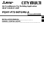 1
1
-
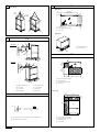 2
2
-
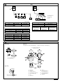 3
3
-
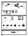 4
4
-
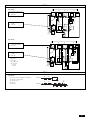 5
5
-
 6
6
-
 7
7
-
 8
8
-
 9
9
-
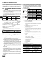 10
10
-
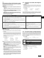 11
11
-
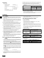 12
12
-
 13
13
-
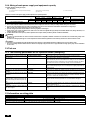 14
14
-
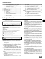 15
15
-
 16
16
-
 17
17
-
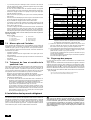 18
18
-
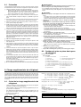 19
19
-
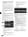 20
20
-
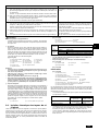 21
21
-
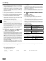 22
22
-
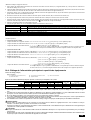 23
23
-
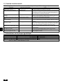 24
24
-
 25
25
-
 26
26
-
 27
27
-
 28
28


Mitsumi electronic Marine Heating System PQHY-P7296TGMU-A Manuel utilisateur
- Taper
- Manuel utilisateur
- Ce manuel convient également à
dans d''autres langues
Autres documents
-
 Bell Sports Bell Sports, Air Conditioner PQRY-P72-96TGMU-A Manuel utilisateur
-
Mitsubishi Electronics R410A Manuel utilisateur
-
Mitsubishi 250YHA2 Guide d'installation
-
Mitsubishi Electric PUHZ-HA2 Guide d'installation
-
-
Mitsubishi Electric PAC-MKA53BC Manuel utilisateur
-
-
-
Toshiba RAV-SP564AT-E Le manuel du propriétaire
-
