Toshiba RAV-SP564AT-E Le manuel du propriétaire
- Catégorie
- Climatiseurs split-system
- Taper
- Le manuel du propriétaire
Ce manuel convient également à

Installation manual
Air conditioner (Split type) 1
English
Manuel d’installation
Climatiseur (Type split) 25
Français
Installationshandbuch
Klimagerät
(Split-typ) 49
Deutsch
Manuale di installazione
Condizionatore d’aria (Tipo split) 73
Italiano
Manual de instalación
Aire acondicionado
(Tipo split) 97
Español
Manual de instalação
Ar condicionado
(Tipo split) 121
Português
Installatiehandleiding
Airconditioner
(Gesplitst type) 145
Nederlands
ǼȖȤİȚȡȓįȚȠ İȖțĮIJȐıIJĮıȘȢ
ȀȜȚȝĮIJȚıIJȚțȩ (įȚĮȚȡȠȣȝİȞȠȣ IJȣʌȠȣ) 169
ǼȜȜȘȞȚțȐ
Ɋɭɤɨɜɨɞɫɬɜɨ ɩɨ ɭɫɬɚɧɨɜɤɟ
Ʉɨɧɞɢɰɢɨɧɟɪ ɜɨɡɞɭɯɚ
(ɫɩɥɢɬ-ɫɢɫɬɟɦɚ)
193
Ɋɭɫɫɤɢɣ
Montaj kılavuzu
Klima (Split tip) 217
Türkçe
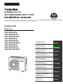
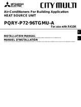
AIR CONDITIONER (SPLIT TYPE)
Installation manual
Outdoor Unit
Model name:
RAV-SP404AT-E
RAV-SP404ATZ-E
RAV-SP404ATZG-E
RAV-SP454AT-E
RAV-SP454ATZ-E
RAV-SP454ATZG-E
RAV-SP564AT-E
RAV-SP564ATZ-E
RAV-SP564ATZG-E

Super Digital Inverter
EN 1
Contents
1 ACCESSORY PARTS . . . . . . . . . . . . . . . . . . . . . . . . . . . . . . . . . . . . . . . . . . . . . . . . . . . . . . . . 2
2 SAFETY PRECAUTIONS . . . . . . . . . . . . . . . . . . . . . . . . . . . . . . . . . . . . . . . . . . . . . . . . . . . . . 3
3 INSTALLATION OF NEW REFRIGERANT AIR CONDITIONER . . . . . . . . . . . . . . . . . . . . . . . 4
4 INSTALLATION CONDITIONS . . . . . . . . . . . . . . . . . . . . . . . . . . . . . . . . . . . . . . . . . . . . . . . . . 7
5 REFRIGERANT PIPING. . . . . . . . . . . . . . . . . . . . . . . . . . . . . . . . . . . . . . . . . . . . . . . . . . . . . . 12
6 AIR PURGING . . . . . . . . . . . . . . . . . . . . . . . . . . . . . . . . . . . . . . . . . . . . . . . . . . . . . . . . . . . . . 15
7 ELECTRICAL WORK. . . . . . . . . . . . . . . . . . . . . . . . . . . . . . . . . . . . . . . . . . . . . . . . . . . . . . . . 17
8 EARTHING . . . . . . . . . . . . . . . . . . . . . . . . . . . . . . . . . . . . . . . . . . . . . . . . . . . . . . . . . . . . . . . . 19
9 FINISHING . . . . . . . . . . . . . . . . . . . . . . . . . . . . . . . . . . . . . . . . . . . . . . . . . . . . . . . . . . . . . . . . 19
10 TEST RUN . . . . . . . . . . . . . . . . . . . . . . . . . . . . . . . . . . . . . . . . . . . . . . . . . . . . . . . . . . . . . . . . 19
11 FUNCTIONS TO BE IMPLEMENTED LOCALLY . . . . . . . . . . . . . . . . . . . . . . . . . . . . . . . . . . 20
12 APPLICABLE OUTDOOR UNIT CONTROL FUNCTIONS . . . . . . . . . . . . . . . . . . . . . . . . . . . 21
13 ANNUAL MAINTENANCE . . . . . . . . . . . . . . . . . . . . . . . . . . . . . . . . . . . . . . . . . . . . . . . . . . . . 21
14 APPENDIX . . . . . . . . . . . . . . . . . . . . . . . . . . . . . . . . . . . . . . . . . . . . . . . . . . . . . . . . . . . . . . . . 22
Please read this Installation Manual carefully before installing the Air Conditioner.
• This Manual describes the installation method of the outdoor unit.
• For installation of the indoor unit, follow the Installation Manual attached to the indoor unit.
ADOPTION OF NEW REFRIGERANT
This Air Conditioner is a new type that has adopted a new refrigerant HFC (R410A) instead of the conventional refrigerant R22 in
order to prevent destruction of the ozone layer.

2 EN
Super Digital Inverter
EN
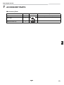
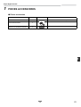
1 ACCESSORY PARTS
Accessory Parts
Part name Q’ty Shape Usage
Installation manual 1 This manual (Hand this directly to the customer.)
Drain nipple 1
Waterproof rubber cap 2

EN 3
Super Digital Inverter
2 SAFETY PRECAUTIONS
• Ensure that all Local, National and International regulations are satisfied.
• Read these “SAFETY PRECAUTIONS” carefully before Installation.
• The precautions described below include important items regarding safety.
Observe them without fail.
• After the installation work, perform a trial operation to check for any problem.
Follow the Owner’s Manual to explain to the customer how to use and maintain the unit.
• Ask the customer to keep the Installation Manual together with the Owner’s Manual.
WARNING
• Ask an authorized dealer or qualified installation professional to install/maintain the air conditioner.
Perform installation work properly according to the Installation Manual.
Inappropriate installation may result in water leakage, electric shock or fire.
• Be sure to connect earth wire. (grounding work)
Incomplete grounding cause an electric shock.
Do not connect ground wires to gas pipes, water pipes, lightning rods or ground wires for telephone wires.
• Turn off the main power supply switch or breaker before attempting any electrical work and maintenance.
Make sure all power switches are off. Failure to do so may cause electric shock.
Use an exclusive power circuit for the air conditioner. Use the rated voltage.
• Connect the connecting wire correctly.
If the connecting wire is incorrect, electric parts may be damaged.
• When moving the air conditioner for installation to another place, be very careful not to allow the specified
refrigerant (R410A) to become mixed with any other gaseous body into the refrigeration cycle.
If air or any other gas mixes with the refrigerant, the gas pressure in the refrigeration cycle will become abnormally high and
it may result in the pipe bursting or personal injuries.
• Do not modify this unit by removing any of the safety guards or by by-passing any of the safety interlock switches.
• Do not touch the intake or aluminum fins of the outdoor unit.
Doing so may result in injury.
• Tighten the flare nut with a torque wrench in the specified manner.
Excessive tightening of the flare nut may cause a crack in the flare nut after a long period, which may result in refrigerant
leakage.
• Install the air conditioner securely in a location where the base can sustain the weight of the unit adequately.
• Perform the specified installation work to guard against an earthquake.
If the air conditioner is not installed appropriately, accidents may occur due to the unit falling.
• If refrigerant gas has leaked during the installation work, ventilate the room immediately.
If the leaked refrigerant gas comes in contact with fire, noxious gas may be generated.
• After the installation work, confirm that refrigerant gas does not leak.
If refrigerant gas leaks into the room and flows near a fire source, such as a cooking range, noxious gas may be generated.
• Electrical work must be performed by a qualified electrician in accordance with the Installation Manual. Make sure
the air conditioner uses an exclusive power supply.
An insufficient power supply capacity or inappropriate installation may cause fire.
• Use only the specified wiring during the unit installation. Ensure that all terminals are securely fixed, so preventing
any external forces having a negative effect on the terminals.
• When the air conditioner cannot cool or heat a room well, contact the dealer from whom you purchased the air
conditioner as refrigerant leakage is considered as the cause.
In the case of repair that requires refill of refrigerant, ask service personnel about details of the repair.
The refrigerant used in the air conditioner is harmless.
Generally, the refrigerant does not leak. However, if the refrigerant leaks in a room and a heater or stove burner in the room
catches fire, it may generate toxic gas.
When you ask service personnel for repairing refrigerant leakage, confirm that the leakage portion has been completely
repaired.
• Conform to the regulations of the local electric company when wiring the power supply.
Inappropriate grounding may cause electric shock.

4 EN
Super Digital Inverter
EN
• Do not install the air conditioner in a location that may be subjected to a risk of exposure to a combustible gas.
If a combustible gas leaks and becomes concentrated around the unit, a fire may occur.
• Install the refrigerant pipe securely during the installation work before operating the air conditioner.
If the compressor is operated with the valve open and without the refrigerant pipe, the compressor sucks air and the
refrigeration cycle is overpressurized, which may cause a burst or injury.
• When carrying out the pump-down work, shut down the compressor before disconnecting the refrigerant pipe.
Disconnecting the refrigerant pipe with the service valve left open and with the compressor still operating will cause air, etc.
to be sucked in, raising the pressure inside the refrigeration cycle to an abnormally high level, and possibly resulting in
rupturing, injury, etc.
CAUTION
• Do not climb onto or place objects on top of the outdoor unit.
You may fall or the objects may fall off of the outdoor unit and result in injury.
• Wear heavy gloves during the installation work to avoid injury.
To Disconnect the Appliance from the Main Power Supply
• This appliance must be connected to the main power supply by means of a switch with a contact separation of at least 3 mm.
• A 16 A installation fuse (all fuse types can be used) must be used for the power supply line of this conditioner.
3 INSTALLATION OF NEW REFRIGERANT AIR
CONDITIONER
CAUTION
New Refrigerant Air Conditioner Installation
• THIS AIR CONDITIONER ADOPTS THE NEW HFC REFRIGERANT (R410A) WHICH DOES NOT DESTROY OZONE
LAYER.
R410A refrigerant is apt to be affected by impurities such as water, oxidizing membrane, and oils because the working pressure
of R410A refrigerant is approx. 1.6 times as that of refrigerant R22. Accompanied with the adoption of the new refrigerant, the
refrigerant oil has also been changed. Therefore, during installation work, be sure that water, dust, former refrigerant, or
refrigerant oil does not enter the new type refrigerant R410A air conditioner circuit.
To prevent mixing of refrigerant or refrigerant oil, the sizes of connecting sections of charging port on main unit and installation
tools are different from those of the conventional refrigerant units. Accordingly, special tools are required for the new refrigerant
(R410A) units. For connecting pipes, use new and clean piping materials with high pressure fittings made for R410A only, so
that water and/or dust does not enter.

EN 5
Super Digital Inverter
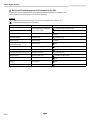
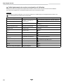
Required Tools/Equipment and Precautions for Use
Prepare the tools and equipment listed in the following table before starting the installation work.
Newly prepared tools and equipment must be used exclusively.
Legend
: Prepared newly (Use for R410A only. Do not use for refrigerant R22 or R407C etc..)
: Conventional tools/equipment are available
Tools/equipment Use How to use tools/equipment
Gauge manifold
Vacuuming/charging refrigerant
and operation check
Prepared newly for R410A only
Charging hose
Prepared newly for R410A only
Charging cylinder Can not be used
Unusable (Use the refrigerant charging measure
instead.)
Gas leak detector Gas leak check
Prepared newly
Vacuum pump Vacuum drying Unusable
Vacuum pump with backflow
prevention function
Vacuum drying
R22
Flare tool Flare machining of pipes
Usable if dimensions are adjusted.
Bender Bending pipes
R22
Refrigerant recovery equipment Refrigerant recovery
For R410A only
Torque wrench Tightening flare nuts
Exclusive for Ø12.7 mm
Pipe cutter Cutting pipes
R22
Welding machine and nitrogen
cylinder
Welding pipes
R22
Refrigerant charging measure Charging refrigerant
R22

6 EN
Super Digital Inverter
EN
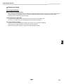
Refrigerant Piping
New refrigerant (R410A)
When using the conventional piping
• When using the conventional piping with no indication of applicable refrigerant types, be sure to use it with a wall thickness
of 0.8 mm for Ø6.4 mm and Ø12.7 mm. Do not use the conventional piping kit with a wall thickness less than these
thicknesses due to insufficient pressure capacity.
When using general copper pipes
• Use general copper pipes with a wall thickness of 0.8 mm for Ø6.4 mm and Ø12.7 mm.
Do not use any copper pipes with a wall thickness less than these thicknesses.
Flare nuts and flare machining
• The flare nuts and flare machining are different from those for the conventional refrigerant.
Use the flare nuts supplied with the air conditioner or those for R410A.
• Before performing flare machining, carefully read “REFRIGERANT PIPING”.

EN 7
Super Digital Inverter
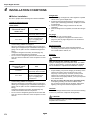
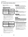
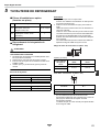
4 INSTALLATION CONDITIONS
Before installation
Be sure to prepare to the following items before installation.
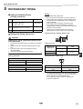
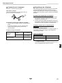
Length of refrigerant pipe
<SP40, SP45>
* Caution during addition of refrigerant
When the total length of refrigerant piping exceeds 20 m,
add 20 g/m of refrigerant up to a maximum total length of
piping at 30 m. (Max. amount of additional refrigerant is
200 g.)
Charge the refrigerant accurately. Overcharging may
cause serious trouble with the compressor.
* Do not connect a refrigerant pipe that is shorter than 5m.
This may cause a malfunction of the compressor or other
devices.
<SP56>
* Caution during addition of refrigerant
When the total length of refrigerant piping exceeds 20 m,
add 20 g/m of refrigerant up to a maximum total length of
piping at 50 m. (Max. amount of additional refrigerant is
600 g.)
Charge the refrigerant accurately. Overcharging may
cause serious trouble with the compressor.
* Do not connect a refrigerant pipe that is shorter than 5m.
This may cause a malfunction of the compressor or other
devices.
Airtight test
1. Before starting an airtight test, further tighten the spindle
valves on the gas and liquid sides.
2. Pressurize the pipe with nitrogen gas charged from the
service port to the design pressure (4.15 Mpa) to conduct
an airtight test.
3. Check for gas leaks using a leak tester for the HFC
refrigerant.
4. After the airtight test is completed, evacuate the nitrogen
gas.
Air purge
• To purge air, use a vacuum pump.
• Do not use refrigerant charged in the outdoor unit to
purge air. (The air purge refrigerant is not contained in
the outdoor unit.)
Electrical wiring
• Be sure to fix the power wires and indoor/outdoor
connecting wires with clamps so that they do not come
into contact with the cabinet, etc.
Earthing
WARNING
Make sure that proper earthing is provided.
Improper earthing may cause an electric shock. For details
on how to check earthing, contact the dealer who installed
the air conditioner or a professional installation company.
• Proper earthing can prevent charging of electricity on the
outdoor unit surface due to the presence of a high
frequency in the frequency converter (inverter) of the
outdoor unit, as well as prevent electric shock. If the
outdoor unit is not properly earthed, you may be exposed
to an electric shock.
• Be sure to connect the earth wire. (grounding work)
Incomplete grounding can cause an electric shock.
Do not connect ground wires to gas pipes, water pipes,
lightning rods or ground wires for telephone wires.
Test Run
Turn on the leakage breaker at least 12 hours before starting
a test run to protect the compressor during startup.
CAUTION
Incorrect installation work may result in a malfunction or
complaints from customers.
Length of refrigerant pipe
connected to indoor/
outdoor unit
Item
5 to 20 m
Addition of refrigerant is
unnecessary at the local site.
*21 to 30 m
<Addition of refrigerant>
Add 20 g of refrigerant for
every 1 m of piping that
exceeds 20 m.
Length of refrigerant pipe
connected to indoor/
outdoor unit
Item
5 to 20 m
Addition of refrigerant is
unnecessary at the local site.
*21 to 50 m
<Addition of refrigerant>
Add 20 g of refrigerant for
every 1 m of piping that
exceeds 20 m.

8 EN
Super Digital Inverter
EN
Installation Location
WARNING
Install the outdoor unit properly in a location that is
durable enough to support the weight of the outdoor
unit.
Insufficient durability may cause the outdoor unit to fall,
which may result in injury.
CAUTION
Do not install the outdoor unit in a location that is
subject to combustible gas leaks.
Accumulation of combustible gas around the outdoor unit
may cause a fire.
Install the outdoor unit in a location that meets the
following conditions after the customer’s consent is
obtained.
• A well-ventilated location free from obstacles near the air
inlets and air outlet
• A location that is not exposed to rain or direct sunlight
• A location that does not increase the operating noise or
vibration of the outdoor unit
• A location that does not produce any drainage problems
from discharged water
Do not install the outdoor unit in the following locations.
• A location with a saline atmosphere (coastal area) or one
that is full of sulfide gas (hot-spring area) (Special
maintenance is required.)
• A location subject to oil, vapor, oily smoke, or corrosive
gases
• A location in which organic solvent is used
• A location where high-frequency equipment
(including inverter equipment, private power generator,
medical equipment, and communication equipment) is
used (Installation in such a location may cause
malfunction of the air conditioner, abnormal control or
problems due to noise from such equipment.)
• A location in which the discharged air of the outdoor unit
blows against the window of a neighboring house
• A location where the operating noise of the outdoor unit is
transmitted
• When the outdoor unit is installed in an elevated position,
be sure to secure its feet.
• A location in which drain water poses any problems.
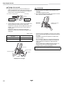
CAUTION
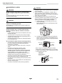
1. Install the outdoor unit in a location where the discharge
air is not blocked.
2. When an outdoor unit is installed in a location that is
always exposed to strong winds like a coast or on the
high stories of a building, secure normal fan operation by
using a duct or wind shield.
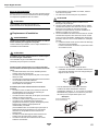
3. When installing the outdoor unit in a location that is
constantly exposed to strong winds such as on the upper
stairs or rooftop of a building, apply the windproofing
measures referred to in the following examples.
1) Install the unit so that its discharge port faces the
wall of the building.
Keep a distance 500 mm or more between the unit
and wall surface.
2) Consider the wind direction during the operational
season of the air conditioner, and install the unit so
that the discharge port is set at a right angle relative
to the wind direction.
• When using an air conditioner under low outside
temperature conditions (Outside temp:-5 °C or lower)
in COOL mode, prepare a duct or wind shield so that it
is not affected by the wind.
500 mm
Strong wind Strong wind
<Example>
Suction hood (Side)
Discharge hood
Fin
Discharge
Suction

EN 9
Super Digital Inverter
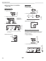
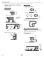
Necessary Space for Installation
(Unit: mm)
Obstacle at rear side
Upper side is free
1. Single unit installation
2. Obstacles on both right and left sides.
3. Serial installation of two or more units
Obstacle also above unit
Obstacle in front
Above unit is free
1. Single unit installation
2. Serial installation of two or more units
Obstacle also at the above unit
Obstacles in both front and rear of unit
Open above and to the right and left of the unit.
The height of an obstacle in both the front and rear of the
unit, should be lower than the height of the outdoor unit.
Standard installation
1. Single unit installation
2. Serial installation of two or more units
150 or
more
200 or
more
150 or
more
300 or
more
The height of the
obstacle should be
lower than the height of
the outdoor unit.
150 or
more
300 or
more
300 or
more
300 or
more
The height of the obstacle should be lower than the height
of the outdoor unit.
200 or more
150 or
more
500 or
more
500 or
more
1,000 or
more
1,000 or
more
1,000 or
more
150 or
more
1,000 or
more
200 or
more
1,000 or
more
300 or
more
300 or
more

10 EN
Super Digital Inverter
EN
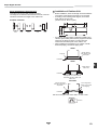
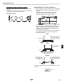
Serial installation in front and rear
Open above and to the right and left of the unit.
The height of an obstacle in both the front and rear of the unit
should be lower than the height of the outdoor unit.
Standard installation
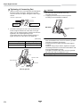
Installation of Outdoor Unit
• Before installation, check the strength and horizontalness
of the base so that abnormal sounds do not emanate.
• According to the following base diagram, fix the base
firmly with the anchor bolts.
(Anchor bolt, nut: M10 x 4 pairs)
• As shown in the figure below, install the foundation and
vibration-proof rubber pads to directly support the bottom
surface of the fixing leg that is in contact with and
underneath the bottom plate of the outdoor unit.
* When installing the foundation for an outdoor unit with
downward piping, consider the piping work.
Set the out margin of the anchor bolt to 15 mm or less.
1,000 or
more
300 or
more
1,500 or
more
2,000 or
more
200 or
more
600
108
90 90
306
60
330
Ø25 Drain hole
GOOD
Fixing leg
Absorb vibration
with vibration-proof
rubber pads
Foundation
GOOD
Bottom plate of
outdoor unit
Foundation
Support the bottom surface of the
fixing leg that is in contact with and
underneath the bottom plate of the
outdoor unit.
NO GOOD
If only the end of the
fixing leg is supported, it
may deform.
Do not support the
outdoor unit only with
the fixing leg.
Foundation
15 or less

EN 11
Super Digital Inverter
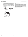
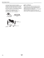
• When water is to be drained through the drain hose,
attach the following drain nipple and waterproof rubber
cap, and use the drain hose (Inner dia.: 16 mm) sold on
the market. Also seal the screws securely with silicone
material, etc., to prevent water from leaking.
Some conditions may cause dewing or dripping of water.
• When collectively draining discharged water completely,
use a drain pan.
For Reference
If a heating operation is to be continuously performed for a
long time under the condition that the outdoor temperature is
0 °C or lower, draining defrosted water may be difficult due to
the bottom plate freezing, resulting in trouble with the cabinet
or fan.
It is recommended to procure an anti-freeze heater locally in
order to safely install the air conditioner.
For details, contact the dealer.
Drain nipple
Waterproof rubber cap
(2pcs.)
Base plate
Drain nipple
Waterproof rubber cap

12 EN
Super Digital Inverter
EN
5 REFRIGERANT PIPING
Optional Installation Parts
(Locally procured)
Refrigerant Piping Connection
CAUTION
TAKE NOTE OF THESE 4 IMPORTANT POINTS BELOW
FOR PIPING WORK
1. Keep dust and moisture away from inside the connecting
pipes.
2. Tightly connect the connection between pipes and the
unit.
3. Evacuate the air in the connecting pipes using a
VACUUM PUMP.
4. Check for gas leaks at connection points.
Piping connection
Flaring
1. Cut the pipe with a pipe cutter.
Be sure to remove burrs that may cause a gas leak.
2. Insert a flare nut into the pipe, and then flare the pipe.
Use the flare nuts supplied with the air conditioner or
those for R410A.
Insert a flare nut into the pipe, and flare the pipe.
As the flaring sizes of R410A differ from those of
refrigerant R22, the flare tools newly manufactured for
R410A are recommended.
However, the conventional tools can be used by
adjusting the projection margin of the copper pipe.
Projection margin in flaring : B (Unit : mm)
Rigid (Clutch type)
Flaring dia. size : A (Unit : mm)
* In case of flaring for R410A with the conventional flare
tool, pull the tool out approx. 0.5 mm more than that for
R22 to adjust it to the specified flare size.
The copper pipe gauge is useful for adjusting the
projection margin size.
Parts name Q’ty
A
Refrigerant piping
Liquid side : Ø6.4 mm
Gas side : Ø12.7 mm
One each
B
Pipe insulating material
(polyethylene foam, 6 mm thick)
1
C Putty, PVC tape One each
Liquid side
Outer diameter Thickness
Ø6.4 mm 0.8 mm
Gas side
Outer diameter Thickness
Ø12.7 mm 0.8 mm
Outer dia. of
copper pipe
R410A tool used
Conventional tool
used
R410A R410A
6.4
0 to 0.5 1.0 to 1.5
12.7
Outer dia. of copper pipe A
6.4 9.9
12.7 16.6
B
A
+0
-0.4

EN 13
Super Digital Inverter
Tightening of Connecting Part
1. Align the centers of the connecting pipes and fully tighten
the flare nut with your fingers. Then fix the nut with a
wrench as shown in the figure and tighten it with a torque
wrench.
2. As shown in the figure, be sure to use two wrenches to
loosen or tighten the flare nut of the valve on the gas
side. If you use a single crescent, the flare nut cannot be
tightened to the required tightening torque.
On the other hand, use a single crescent to loosen or
tighten the flare nut of the valve on the liquid side.
(Unit: N•m)
CAUTION
1. Do not put the crescent wrench on the cap.
The valve may break.
2. If applying excessive torque, the nut may break
according to some installation conditions.
• After the installation work, be sure to check for gas leaks
of the pipe connections with nitrogen.
• Pressure of R410A is higher than that of R22 (Approx.
1.6 times).
Therefore, using a torque wrench, tighten the flare pipe
connecting sections that connect the indoor/outdoor units
at the specified tightening torque.
Incomplete connections may cause not only a gas leak,
but also trouble with the refrigeration cycle.
Outer dia. of copper pipe Tightening torque
6.4 mm (dia.) 14 to 18 (1.4 to 1.8 kgf•m)
12.7 mm (dia.) 50 to 62 (5.0 to 6.2 kgf•m)
Half union or packed valve Flare nut
Externally
threaded side
Internally threaded
side
Fix with wrench. Tighten with torque wrench.
Wrench for work
Flare nut
Cap
Wrench for fixing
Valve at gas side
Loosened
Tightened
Do not apply refrigerant oil to the flared surface.
NO GOOD
Use of single wrench is
prohibited

14 EN
Super Digital Inverter
EN
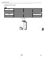
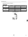
Refrigerant Pipe Length
Single
Model
Allowable pipe length (m) Height difference (Indoor-outdoor H) (m)
Total length L Indoor unit: Upper Outdoor unit: Lower
SP40, 45 30 30 30
SP56 50 30 30
Model
Pipe diameter (mm)
Number of bent portions
Gas side Liquid side
SP40, 45 Ø12.7 Ø6.4 10 or less
SP56 Ø12.7 Ø6.4 10 or less
H
L
Figure of Single
Indoor Unit
Outdoor Unit

EN 15
Super Digital Inverter
6 AIR PURGING
Airtight test
Before starting an airtight test, further tighten the spindle
valves on the gas side and liquid side.
Pressurize the pipe with nitrogen gas charged from the
service port to the design pressure (4.15 Mpa) to conduct the
airtight test. Perform gas leak checks using a leak tester for
the HFC refrigerant.
After the airtight test is completed, evacuate the nitrogen
gas.
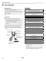
Air Purge
With respect to the preservation of the terrestrial
environment, adopt “Vacuum pump” to purge air (Evacuate
air in the connecting pipes) when installing the unit.
• Do not discharge the refrigerant gas to the atmosphere to
preserve the terrestrial environment.
• Use a vacuum pump to discharge the air (nitrogen, etc.)
that remains in the set. If air remains, the capacity may
decrease.
For the vacuum pump, be sure to use one with a backflow
preventer so that the oil in the pump does not backflow into
the pipe of the air conditioner when the pump stops.
(If oil in the vacuum pump is put in an air conditioner
including R410A, it may cause trouble with the refrigeration
cycle.)
Vacuum pump
*1
Use the vacuum pump, vacuum pump adapter, and gauge
manifold correctly referring to the manuals supplied with each
tool before using them.
Check that the vacuum pump oil is filled up to the specified line
of the oil gauge.
*2
When air is not charged, check again whether the connecting
port of the discharge hose, which has a projection to push the
valve core, is firmly connected to the charge port.
Pressure gauge
Gauge manifold valve
Handle High
(Keep fully closed)
Compound pressure gauge
Charge hose
(For R410A only)
Vacuum pump adapter for
counter-flow prevention
(For R410A only)
–101 kPa
(–76 cmHg)
Handle Low
Charge hose
(For R410A only)
Charge port
(Valve core (Setting pin))
Packed valve at gas side
Vacuum
pump
As shown in the figure, connect the charge hose after the
manifold valve is closed completely.
L
Attach the connecting port of the charge hose with a
projection to push the valve core (setting pin) to the charge
port of the set.
L
Open Handle Low fully.
L
Turn ON the vacuum pump (*1)
L
Loosen the flare nut of the packed valve (Gas side) a little to
check that the air passes through. (*2)
L
Retighten the flare nut.
L
Execute vacuuming until the compound pressure gauge
indicates –101 kPa (–76 cmHg). (*1)
L
Close Handle Low completely.
L
Turn OFF the vacuum pump.
L
Leave the vacuum pump as it is for 1 or 2 minutes, and
check that the indicator of the compound pressure gauge
does not return.
L
Open the valve stem or valve handle fully. (First, at liquid
side, then gas side)
L
Disconnect the charge hose from the charge port.
L
Tighten the valve and caps of the charge port securely.

16 EN
Super Digital Inverter
EN
How to open the valve
Open or close the valve.
Liquid side, gas side
Open the valve with a 4 mm hexagon wrench.
[Hexagonal wrench is required.]
Valve handling precautions
• Open the valve stem until it strikes the stopper.
It is unnecessary to apply further force.
• Securely tighten the cap with a torque wrench.
Cap tightening torque
Replenishing refrigerant
This model is a 20 m chargeless type that does not need to
have its refrigerant replenished for refrigerant pipes up to
20 m. When a refrigerant pipe longer than 20 m is used, add
the specified amount of refrigerant.
Refrigerant replenishing procedure
1. After vacuuming the refrigerant pipe, close the valves
and then charge the refrigerant while the air conditioner
is not working.
2. When the refrigerant cannot be charged to the specified
amount, charge the required amount of refrigerant from
the charge port of the valve on the gas side during
cooling.
Requirement for replenishing refrigerant
Replenish liquid refrigerant.
When gaseous refrigerant is replenished, the refrigerant
composition varies, which disables normal operation.
Adding additional refrigerant
• L: Pipe length
• The refrigerant need not be reduced for a 20 meter (or
less) refrigerant pipe.
Valve size
Ø6.4 mm
14 to 18 N•m
(1.4 to 1.8 kgf•m)
Ø12.7 mm
33 to 42 N•m
(3.3 to 4.2 kgf•m)
Charge port
14 to 18 N•m
(1.4 to 1.8 kgf•m)
4 mm
SP40, 45 SP56
21~30 m: L 21~50 m: L
20 g × (L-20) 20 g × (L-20)

EN 17
Super Digital Inverter
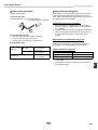
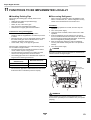
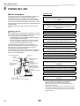
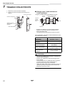
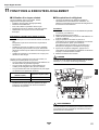
7 ELECTRICAL WORK
1. Remove valve cover screw.
2. Pull the valve cover downward to remove it.
Wiring between Indoor Unit and Out-
door Unit
The dashed lines show on-site wiring.
• Connect the indoor/outdoor connecting wires to the
identical terminal numbers on the terminal block of each
unit.
Incorrect connection may cause a failure.
For the air conditioner, connect a power wire with the
following specifications.
CAUTION
• Wrong wiring may cause a burn-out of some electrical
parts.
• Be sure to use the cord clamps attached to the product.
• Do not damage or scratch the conductive core or inner
insulator of the power and inter-connecting wires when
peeling them.
• Use the power and Inter-connecting wires with specified
thicknesses, specified types and protective devices
required.
Valve cover
Piping cover
Indoor/outdoor
connecting wires
Power wire
Model RAV- SP40, SP45, SP56
Power supply 220-240 V~, 50 Hz
Maximum running current 15 A
Installation fuse rating 16 A (all types can be used)
Power wire
H07 RN-F or 60245 IEC 66
(2.5 mm
2
or more)
Indoor/outdoor connecting
wires
H07 RN-F or 60245 IEC 66
(1.5 mm
2
or more)
L
N
1
2
3
1
2
3
(Main circuit)
(Indoor/outdoor
connecting wires)
Outdoor unit
Remote
controller
Indoor unit
Earth
Leakage
breaker
Input power
220-240 V~,
50 Hz

18 EN
Super Digital Inverter
EN
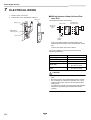
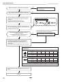
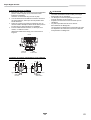
How to wire
1. Connect the connecting wire to the terminal as identified
with their respective numbers on the terminal block of the
indoor and outdoor units.
H07 RN-F or 60245 IEC 66 (1.5 mm
2
or more)
2. When connecting the connecting wire to the outdoor unit
terminal, prevent water from coming into the outdoor unit.
3. Insulate the unsheathed cords (conductors) with
electrical insulation tape. Process them so that they do
not touch any electrical or metal parts.
4. For interconnecting wires, do not use a wire joined to
another on the way.
Use wires long enough to cover the entire length.
Stripping length power cord and connecting wire
CAUTION
• An installation fuse must be used for the power supply
line of this air conditioner.
• Incorrect/incomplete wiring may lead to an electrical fire
or smoke.
• Prepare an exclusive power supply for the air conditioner.
• This product can be connected to the mains power.
Fixed wire connections :
A switch that disconnects all poles and has a contact
separation of at least 3 mm must be incorporated in the
fixed wiring.
123LN
Terminal block
Screw
Connecting wire Power wire
(mm)
1010
1010
LN
3030
4040
123
Earth line
Connecting wire
Earth line
Power wire

EN 19
Super Digital Inverter
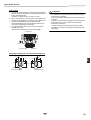
8 EARTHING
WARNING
• Be sure to connect the earth wire. (grounding work)
Incomplete grounding may cause an electric shock.
Connect the earth line properly following applicable technical standards.
Connecting the earth line is essential to preventing electric shock and to reducing noise and electrical charges on the outdoor
unit surface due to the high-frequency wave generated by the frequency converter (inverter) in the outdoor unit.
If you touch the charged outdoor unit without an earth line, you may experience an electric shock.
9 FINISHING
After the refrigerant pipe, inter-unit wires, and drain pipe have been connected, cover them with finishing
tape and clamp them to the wall with off-the-shelf support brackets or their equivalent.
Keep the power wires and indoor/outdoor connecting wires off the valve on the gas side or pipes that have no heat insulator.
10
TEST RUN
• Turn on the leakage breaker at least 12 hours before starting a test run to protect the compressor during startup.
To protect the compressor, power is supplied from the 220-240 VAC input to the unit to preheat the compressor.
• Check the following before starting a test run:
• That all pipes are connected securely without leaks.
• That the valve is open.
If the compressor is operated with the valve closed, the outdoor unit will become overpressurized, which may damage the
compressor or other components.
If there is a leak at a connection, air can be sucked in and the internal pressure further increases, which may cause a burst
or injury.
• Operate the air conditioner in the correct procedure as specified in the Owner’s Manual.
La page est en cours de chargement...
La page est en cours de chargement...
La page est en cours de chargement...
La page est en cours de chargement...
La page est en cours de chargement...
La page est en cours de chargement...
La page est en cours de chargement...
La page est en cours de chargement...
La page est en cours de chargement...
La page est en cours de chargement...
La page est en cours de chargement...
La page est en cours de chargement...
La page est en cours de chargement...
La page est en cours de chargement...
La page est en cours de chargement...
La page est en cours de chargement...
La page est en cours de chargement...
La page est en cours de chargement...
La page est en cours de chargement...
La page est en cours de chargement...
La page est en cours de chargement...
La page est en cours de chargement...
La page est en cours de chargement...
La page est en cours de chargement...
La page est en cours de chargement...
La page est en cours de chargement...
La page est en cours de chargement...
La page est en cours de chargement...
La page est en cours de chargement...
La page est en cours de chargement...
-
 1
1
-
 2
2
-
 3
3
-
 4
4
-
 5
5
-
 6
6
-
 7
7
-
 8
8
-
 9
9
-
 10
10
-
 11
11
-
 12
12
-
 13
13
-
 14
14
-
 15
15
-
 16
16
-
 17
17
-
 18
18
-
 19
19
-
 20
20
-
 21
21
-
 22
22
-
 23
23
-
 24
24
-
 25
25
-
 26
26
-
 27
27
-
 28
28
-
 29
29
-
 30
30
-
 31
31
-
 32
32
-
 33
33
-
 34
34
-
 35
35
-
 36
36
-
 37
37
-
 38
38
-
 39
39
-
 40
40
-
 41
41
-
 42
42
-
 43
43
-
 44
44
-
 45
45
-
 46
46
-
 47
47
-
 48
48
-
 49
49
-
 50
50


Toshiba RAV-SP564AT-E Le manuel du propriétaire
- Catégorie
- Climatiseurs split-system
- Taper
- Le manuel du propriétaire
- Ce manuel convient également à
dans d''autres langues
- English: Toshiba RAV-SP564AT-E Owner's manual
Documents connexes
-
Toshiba MMD-AP0181SPH Le manuel du propriétaire
-
Toshiba MCY-MAP0601HT Le manuel du propriétaire
-
Toshiba RAV-SP1604AT8-E Le manuel du propriétaire
-
Toshiba SUZUMI + RAS-B22N3KV2-E1 Le manuel du propriétaire
-
-
-
Autres documents
-
Chariot Carriers Merci Guide d'installation
-
Haier 1U28HS1ERA Guide d'installation
-
Carrier 38VBH...S Guide d'installation
-
Haier 2U18FS2ERA Le manuel du propriétaire
-
Acson ALC015BR Guide d'installation
-
-
Mitsubishi MXZ-2B20NA Guide d'installation
-
-
Mitsumi electronic Marine Heating System PQHY-P7296TGMU-A Manuel utilisateur
-
 Bell Sports Bell Sports, Air Conditioner PQRY-P72-96TGMU-A Manuel utilisateur
