Lifetime 90143 Le manuel du propriétaire
- Taper
- Le manuel du propriétaire

1
Keep this Product ID Number and use when contacting Customer Service:
MODEL N° 90143
OWNER’S MANUAL
COPY

2
INSTRUCTION #1079890 C
3/02/2011
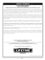
REGISTER YOUR LIFETIME PRODUCT TODAY!
LIFETIME’S PROMISE TO YOU:
We invite you to read our privacy policy at www.lifetime.com
REGISTER today!
There are benefi ts to registering your Lifetime product. With our new online product registration form, it’s fast and easy! Register with us at www.lifetime.com
and enjoy these great benefi ts:
s2ECEIVEEXCLUSIVEMONEYSAVINGOFFERSFROM"UY,IFETIMECOMOURONLINESTOREASWELLAS.%7PRODUCTNOTIlCATIONSANDSPECIALCLOSEOUT
PROMOTIONS
s)NTHEUNLIKELYEVENTOFAPRODUCTRECALLORSAFETYMODIlCATIONWEWILLNOTIFYYOU
s2EGISTERINGYOURPRODUCTGUARANTEESYOUWARRANTYSERVICE)FYOUDONOTREGISTERYOURPRODUCTYOURWARRANTYRIGHTSWILLNOTBEDIMINISHED
"UTYOUWILLNEEDTOPROVIDEASALESRECEIPTTOVERIFYYOURPRODUCTPURCHASEDATEBEFOREWARRANTYSERVICEWILLBEPROVIDED
Maintaining your privacy is our long-standing policy at Lifetime. And you can rest assured that Lifetime will not sell or provide your
personal data to other third parties, or allow them to use your personal data for their own purposes.
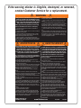
Most injuries are caused by misuse and/or not following instructions. Use caution when using this product.
4OENSURESAFETYDONOTATTEMPTTOASSEMBLETHISPRODUCTWITHOUTREADINGANDFOLLOWINGALLINSTRUCTIONSCAREFULLY#HECKTHEENTIRE
BOXANDINSIDEALLPACKINGMATERIALSFORPARTSANDORADDITIONALINSTRUCTIONMATERIAL"EFOREBEGINNINGASSEMBLYIDENTIFYANDINVENTORY
ALLPARTSANDHARDWAREUSINGTHEPARTSANDHARDWARELISTSANDIDENTIlERSINTHISDOCUMENT0ROPERANDCOMPLETEASSEMBLYUSEAND
SUPERVISIONAREESSENTIALFORPROPERORIENTATIONANDTOREDUCETHERISKOFACCIDENTORINJURY!HIGHPROBABILITYOFSERIOUSINJURYEXISTS
IFTHISPRODUCTISNOTINSTALLEDMAINTAINEDANDOROPERATEDPROPERLY&AILURETOCOMPLYWITHANYOFTHEWARNINGSINTHISINSTRUCTION
MANUALMAYRESULTINSERIOUSPERSONALINJURIESSUCHASCUTSBROKENBONESNERVEDAMAGEPARALYSISBRAININJURYORDEATH&AILURETO
COMPLYMAYALSORESULTINPROPERTYDAMAGE0LEASEHEEDALLWARNINGSANDCAUTIONS
FAILURE TO FOLLOW THESE WARNINGS MAY RESULT IN SERIOUS INJURY OR PROPERTY
DAMAGE AND WILL VOID WARRANTY.
SAFETY INSTRUCTIONS
Save this owner’s manual for future reference and in the event that the manufacturer has to be contacted.
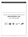
**U.S. and Canada customers ONLY**
)&!33)34!.#%)3.%%$%$
DO NOT CONTACT THE STORE!
CALL OUR CUSTOMER SERVICE DEPARTMENT at 1 (800) 225-3865
(/523AMTOPM-ONDAYTHROUGH&RIDAY-OUNTAIN3TANDARD4IME
#ALLORVISITOUR7EBSITEFOR3ATURDAYHOURS
Lifetime Products, Inc.
0/"OXs&REEPORT#ENTER"LDG$#LEARFIELD5TAH
&ORCUSTOMERSOUTSIDETHE53OR#ANADAPLEASECONTACTTHESTOREFORASSISTANCE
This product is intended for use by children ages 3 to 12,
and is for outdoor residential use only.
COPY

3
BEFORE BEGINNING ASSEMBLY
+EEPTHEHARDWAREBAGSANDTHEIRCONTENTSSEPARATE)FANYPARTSAREMISSINGCALLOUR
#USTOMER3ERVICE$EPARTMENT
)DENTIFY AND INVENTORY ALL PARTS AND HARDWARE USING THE PARTS AND HARDWARE LISTS AND
IDENTIlERSINTHISDOCUMENT
4ESTlTALL"OLTSBYINSERTINGTHEMINTOTHEIRRESPECTIVEHOLES)FNECESSARYCAREFULLY
SCRAPEAWAYANYEXCESSPOWDERCOATINGBUILDUPFROMINSIDETHEHOLES$ONOTSCRAPE
AWAYALLOFTHEPOWDERCOATING"AREMETALMAYRUST9OUMAYNEEDTOPOUNDSOME
"OLTSINTOPLACEWITHAHAMMERORMALLET
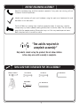
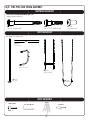
TOOLS AND PARTS REQUIRED FOR THIS ASSEMBLY
*Two adults required to
complete assembly*
Only adults should set up the product. Do not allow children
in the setup area until assembly is complete.
3/16” Allen Wrench
INCLUDED
1/2” Wrench
Phillips Screwdriver
11/16” Wrench
Ladder
Rubber Mallet
1/4” Allen Wrench
INCLUDED

4
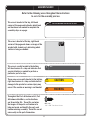
This area is located at the top, left-hand
corner of the page and indicates which tools
and hardware are needed to complete the
assembly steps on a page.
This area is located at the top, right-hand
corner of the page and shows an image of the
product with shaded parts indicating which
section is being assembled.
SEC
#
Note:
!
Refer to the following areas throughout the instructions
to assist in the assembly process:
This area is usually located in the bottom,
left-hand corner of a step and indicates that
special attention is needed to perform a
particular part of a step.
These areas are usually located in the bottom,
right-hand corner of a step and indicate that
damage to the product or serious injury may
occur if the caution or warning is not heeded.
Throughout the Parts & Hardware List, Part
& Hardware Identifi ers, and instructions
are three-letter IDs. These IDs are below
the images of the parts and hardware to
help you locate and identify the parts and
hardware during assembly. These IDs are not
necessarily on the parts themselves.
WARNING
ASSEMBLY GUIDES
TOOLS AND HARDWARE REQUIRED FOR THIS PAGE
CAUTION
ADZX
vXv0AN(EAD3CREW

5
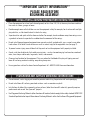
**IMPORTANT SAFETY INFORMATION**
PLEASE READ BEFORE
BEGINNING ASSEMBLY:
Place the equipment on a level, well-drained ground, not less than 6 ft (1.8 m) from any structure or obstruc-s
tion such as a fence, garage, or house.
Provide enough room so that children can use the equipment safely. For example, for structures with multiple s
play activities, a slide should not exit in front of a swing.
Separate active and quiet activities from each other. For example, locate sandboxes away from swings or use s
a guardrail or barrier to separate the sandbox from the movement of the swings.
Do not install home playground equipment over concrete, asphalt, packed earth, grass, carpet, or any other s
hard surface. A fall onto a hard surface can result in serious injury to the equipment user (see page 7).
To prevent serious injury, warn children that they must not use the equipment until properly installed.s
Create a site free of obstacles that could cause injuries – such as low overhanging tree branches, overhead s
wires, tree stumps and/or roots, large rocks, bricks, and concrete.
Choose a level location for the equipment. This can reduce the likelihood of the play set tipping over and s
loose-fill surfacing materials washing away during heavy rains
For any questions call our Customer Service Department at 1-800-225-3865 for more information.s
Use containment, such as digging out around the perimeter and/or lining the perimeter with landscape edging.s
Do not install loose fill surfacing over hard surfaces such as concrete or asphalt.s
Installations of rubber tiles or poured-in-place surfaces (other than loose-fill materials) generally require a s
professional and are not “do-it yourself” projects.
Use Playground Surfacing Materials (other than loose-fill material) which comply to the safety standard ASTM F1292 s
Standard Specification for Impact Attenuation of Surfacing Materials within the Use Zone of Playground Equipment.
INSTALLATION & GROUND PREPARATION INSTRUCTIONS
PLAYGROUND AND SURFACE MATERIALS INSTRUCTIONS

6
OPERATING INSTRUCTIONS
Observing the following instructions and warnings reduces the likelihood of serious or fatal injury:
The maximum number of occupants that may safely use the entire play set including all components is six s
with a maximum weight of 640 pounds
(290 kg).
On-site adult supervision should be provided for children of all ages.s
Instruct children not to walk close to, in front of, behind, or between moving items.s
Do not move the equipment while it is in use.s
Instruct children not to twist swing chains or ropes or loop them over the top support bar since this may s
reduce the strength of the chain or rope.
Instruct children to avoid swinging empty seats.s
Teach children to sit in the center of the swings with their full weight on the seats.s
Instruct children not to use the equipment in a manner other than intended. s
Instruct children not to get off the equipment while it is in motion.s
To prevent entanglement and strangulation, dress children appropriately using well-fitting shoes and avoiding s
ponchos, scarves, jackets with neck drawstrings, helmets with straps, and other loose-fitting clothing that is
potentially hazardous while using equipment.
Instruct children not to play when the equipment is wet.s
Instruct children not to attach items to the playground equipment that are not specifically designed for use s
with the equipment, such as, but not limited to, jump ropes, clothesline, pet leashes, cables and chain as
they may cause a strangulation hazard.

7
MAINTENANCE INSTRUCTIONS
If routine checks and maintenance procedures are not done, the equipment could overturn and/or become a hazard.
At the beginning of each play season:
Tighten all hardware.s
Lubricate all metallic moving parts.s
Check all protective coverings on bolts, pipes, edges and corners. Replace if they are loose, cracked or missing.s
Check all moving parts including swing seats, ropes, cables and chains for wear, rust or other deterioration. s
Contact customer service for replacement parts.
Check metal parts for rust. If found, sand and repaint using a non lead-based paint meeting the requirements s
of 16 CFR 1303.
Reinstall any plastic parts, such as swing seats or any other items that were removed for the cold season.s
Rake and check depth of loose fill protective surfacing materials to prevent compaction and to maintain appro-s
priate depth. Replace as necessary. (See page 5)
Twice a month during play season:
Tighten all hardware.s
Check all protective coverings on bolts, pipes, edges and corners. Replace if they are loose, cracked or missing.s
Rake and check depth of loose fill protective surfacing materials to prevent compaction and to maintain appro-s
priate depth. Replace as necessary. (See page 5)
Once a month during play season:
Lubricate all metallic moving parts.s
Check all moving parts including swing seats, ropes, cables and chains for wear, rust or other deterioration. s
Contact customer service for replacement parts.
At the end of each play season or when the temperature drops below 40
o
F (5
o
C):
Remove plastic swing seats and the trapeze swing and take them indoors or do not use.s
Rake and check depth of loose fill protective surfacing materials to prevent compaction and to maintain appro-s
priate depth. Replace as necessary. (See page 5)
If the warning sticker is illegible, destroyed, or removed contact the Customer Service Department at s
1-800-225-3865 for a replacement.
Disposal Instructions: Disassemble and dispose of the playground equipment in such a way that no unreason-
able hazards will exist at the time the equipment is discarded. Follow all local disposal requirements.

8
The U.S. Consumer Product Safety Commission (CPSC)
estimates that about 100,000 playground equipment re-
lated injuries resulting from falls to the ground surface are
treated annually in U.S. hospital emergency rooms. Injuries
involving this hazard pattern tend to be among the most
serious of all playground injuries, and have the potential
to be fatal, particularly when the injury is to the head. The
surface under and around playground equipment can be a
major factor in determining the injury causing potential of a
fall. It is self evident that a fall onto a shock-absorbing sur-
face is less likely to cause a serious injury than a fall onto a
hard surface. Playground equipment should never be placed
on hard surfaces such as concrete or asphalt and while
grass may appear to be acceptable, it may quickly turn to
hard packed earth in areas of high traffic. Shredded bark
mulch, wood chips, fine sand or fine gravel are considered
to be acceptable shock-absorbing surfaces when installed
and maintained at a sufficient depth under and around
playground equipment.
Table 1 lists the maximum height from which a child would
not be expected to sustain a life-threatening head injury in
a fall onto different loose-fill surfacing materials if they are
installed and maintained at depths of 6, 9, and 12 inches.
However, it should be recognized that all injuries due to falls
cannot be prevented no matter what surfacing material is
used.
It is recommended that a shock-absorbing material should
extend a minimum of 6 ft. in all directions from the perim-
eter of stationary equipment such as climbers and slides.
However, because children may deliberately jump from a
moving swing, the shock absorbing material should extend
in the front and rear of a swing a minimum distance of 2
times the height of the pivot point measured from a point
directly beneath the pivot on the supporting structure.
This information is intended to assist in comparing the
relative shock-absorbing properties of various materials. No
particular material is recommended over another. However,
each material is only effective when properly maintained.
Materials should be checked periodically and replenished
to maintain correct depth as determined necessary for your
equipment. The choice of a material depends on the type
and height of the playground equipment, the availability of
the material in your area, and its cost.
*This information has been extracted from the CPSC publications “Playground Surfacing--Technical Information Guide” and “Handbook for
Public Playground Safety.” Copies of these reports can be obtained by sending a postcard to the: Office of Public Affairs, U.S. Consumer Product
Safety Commission, Washington, D.C., 20207 or call the toll-free hotline: 1-800-638-2772.
***This data is from tests conducted by independent testing laboratories on a 6-inch depth of uncompressed shredded tire samples produced
by four manufacturers. It is recommended that persons seeking to install shredded tires as a protective surface request test data from the sup-
plier showing the critical height of the material when it was tested in accordance with ASTM F1292.
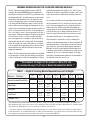
CONSUMER INFORMATION SHEET FOR PLAYGROUND SURFACING MATERIALS*
**The maximum fall height for this product is 108 in (274 cm).
We recommend using 9 in (23 cm) of Double Shredded Bark Mulch.**
5 ft 6 ft 7 ft 9 ft 10 ft 11 ft 12 ft
-- 6 in -- -- 9 in 12 in --
-- 6 in 9 in -- -- -- 12 in
6 in -- 9 in 12 in -- -- --
-- 6 in 9 in -- 12 in -- --
-- -- -- -- 6 in -- --
TABLE 1 — Depth of Surfacing Material Required Based on Fall Heights
Material / Fall Height
Double Shredded Bark Mulch
Wood Chips
Fine Sand
Fine Gravel
Shredded Tires***
(152 cm)
(183 cm) (213 cm)
(274 cm)
(305 cm) (335 cm) (366 cm)
(15 cm)
(23 cm) (30 cm)
(15 cm) (23 cm) (30 cm)
(30 cm)
(23 cm)(15 cm)
(15 cm)
(23 cm)
(30 cm)
(15 cm)

9
A cordless drill can be used for driving screws;
however, care should be taken not to over-tighten or strip screws.
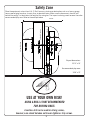
USE AT YOUR OWN RISK!
Safety Zone
USING A DRILL IS NOT RECOMMENDED
FOR DRIVING BOLTS.
0LACETHEEQUIPMENTNOLESSTHANFTMFROMANYSTRUCTUREOROBSTRUCTIONSUCHASAFENCEGARAGE
HOUSEOVERHANGINGBRANCHESLAUNDRYLINESORELECTRICALWIRES-AKESURETHECLEARANCEINFRONTOFAND
BEHINDTHESWINGSISATLEASTTWICETHEHEIGHTOFTHESWINGBAR4HEIMPACTSURFACINGNEEDSTOCOVERTHEENTIRE
RECOMMENDEDPLAYAREA2EFERTOTHEEXAMPLEBELOW
Playset dimensions:
13’ 11” x 15’
Recommended play area:
29’ 8” x 27’
27 feet
29 feet 8 inches
6 feet
6 feet
6 feet
14 feet 10 inches
14 feet 10 inches
6 feet
6 feet

10
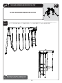
HARDWARE LIST
PARTS LIST
ID Item Description Qty
PLAYGROUND PARTS
"%+ 3LIDE
"%/ 3LIDE$ECK
CVM ADVENTURE SET PARTS KIT 1
#") 4URN"AR
#2: !NCHOR2OD
#29 3LIDE,ADDER
#21 3LIDE2AIL
#20 -ONKEY"ARS'USSET
#76 -ONKEY"ARS'USSETWITH,OGO
#28 &IRE0OLE,ADDER
#3# -ONKEY"ARS
#23 &IRE0OLE(OOP
#25 $ECK3UPPORT
ID Item Description Qty
CVN ADVENTURE SET PARTS KIT 2
#"' !&RAME0OLE
#24 &IRE0OLE
#22 4RAPEZE3WING"AR
#"/ 3WING"AR
CVO ADVENTURE SET PARTS KIT 3
"+4 "ELT3WING 3
"+5 4RAPEZE3WING
#3" 2OUND&OOT#AP
#3! 3ADDLE#AP
#3$ 2OUND%ND#AP
":* !NGLED&OOT#AP
ID Item Description Qty
CAM A-Frame Assembly Hardware
":+ v#AP0LUG
!21 vXv"UTTON(EAD"OLT
!20 Pendulum
!22 v!CORN.UT
!23 v3MALL.YLON7ASHER
!24 v,ARGE.YLON7ASHER
"43 v"ARREL.UT
":/ vXv3HOULDER"OLT
##, v!LLEN7RENCHNOTPICTURED
!30 v!LLEN7RENCHNOTPICTURED
CVH Monkey Bars Assembly Hardware
":+ v#AP0LUG
!21 vXv"UTTON(EAD"OLT
!20 Pendulum
!22 v!CORN.UT
!23 v3MALL.YLON7ASHER
!24 v,ARGE.YLON7ASHER
"43 v"ARREL.UT
":/ vXv3HOULDER"OLT
CAH Slide Assembly Hardware
"43 v"ARREL.UT
":/ vXv3HOULDER"OLT
":. vXv3HOULDER"OLT
!28 vXv"UTTON(EAD"OLT 3
!2- v!CORN.UT 3
!2, v7ASHER
#6: v7ASHER
CVI Fire Pole Assembly Hardware
"43 v"ARREL.UT 3
":/ vXv3HOULDER"OLT
":. vXv3HOULDER"OLT

11
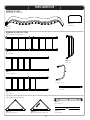
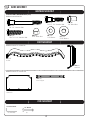
PARTS IDENTIFIER
ADVENTURE SET PARTS KIT 1 [CVM]
Parts shown at 5% of actual size
24”
CRQX
3LIDE2AIL
BEOX
3LIDE$ECK
CRZX
!NCHOR2OD
CRUX
$ECK3UPPORT
CRSX
&IRE0OLE(OOP
CRXX
&IRE0OLE,ADDER
CRYX
3LIDE,ADDER
CSCX
-ONKEY"ARS
CRPX
-ONKEY"ARS'USSET
Parts shown at 10% of actual size
CBIX
4URN"AR
ADVENTURE SET PARTS
Part shown at 5% of actual size
BEKX
3LIDE
CWVX
-ONKEY"ARS'USSETWITH,OGO

12
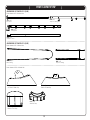
PARTS IDENTIFIER
ADVENTURE SET PARTS KIT 3 [CVO]
Parts shown at 5% of Actual Size
BKTX
"ELT3WING
BKUX
4RAPEZE3WING
BZJX
!&RAME&OOT#AP
CSBX
2OUND&OOT#AP
CSAX
3ADDLE#AP
CSDX
2OUND%ND#AP
Parts shown at 50% of Actual Size
ADVENTURE SET PARTS KIT 2 [CVN]
Parts shown at 5% of actual size
CBOX
3WING"AR
CBGX
!&RAME0OLE
CRRX
4RAPEZE3WING"AR
CRTX
&IRE0OLE

13
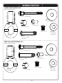
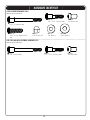
HARDWARE IDENTIFIER
MONKEY BARS ASSEMBLY HARDWARE [CVH]
Hardware shown at Actual Size
A-FRAME ASSEMBLY HARDWARE [CAM]
Hardware shown at Actual Size
ARPX
Pendulum
ARQX
vXv"UTTON
(EAD"OLT
ARRX
v!CORN.UT
ARSX
v3MALL
.YLON7ASHER
ARTX
v,ARGE.YLON7ASHER
BZOX
vXv3HOULDER"OLT
BTSX
v"ARREL.UT
BZKX
#AP0LUG
ARPX
Pendulum
ARQX
vXv"UTTON
(EAD"OLT
ARSX
v3MALL
.YLON7ASHER
ARTX
v,ARGE.YLON7ASHER
BZOX
vXv3HOULDER"OLT
BTSX
v"ARREL.UT
BZKX
v#AP0LUG
ARRX
v!CORN.UT

14
HARDWARE IDENTIFIER
SLIDE ASSEMBLY HARDWARE [CAH]
Hardware shown at Actual Size
FIRE POLE AND SWING ASSEMBLY HARDWARE [CVI]
Hardware shown at Actual Size
BTSX
v"ARREL.UT
BZOX
vXv3HOULDER"OLT
BZNX
vXv3HOULDER"OLT
ARLX
v7ASHER
ARXX
vXv"UTTON(EAD
"OLT
ARMX
v!CORN.UT
BZOX
vXv3HOULDER"OLT
BTSX
v"ARREL.UT
BZNX
vXv3HOULDER"OLT
CVZX
v7ASHER

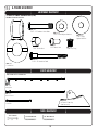
15
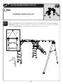
A-FRAME ASSEMBLY
HARDWARE REQUIRED
SEC
1
A-FRAME ASSEMBLY HARDWARE BAG [CAM]
Hardware shown at actual size
ARPX
Pendulum
BZOX
vXv3HOULDER"OLT
BTSX
v"ARREL.UT
BZKX
#AP0LUG
BZJX
!&RAME&OOT#AP
NOTTOSCALE
ARQX
vXv"UTTON(EAD"OLT
ARRX
v!CORN.UT
ARSX
v3MALL.YLON7ASHER
ARTX
v,ARGE
.YLON7ASHER
TOOLS REQUIRED
PARTS REQUIRED
Parts shown at 5% of Actual Size
3/16” Allen Wrench
CBGX
!&RAME0OLE
CB0X
3WING"AR
CBIX
4URN"AR
11/16” Wrench
INCLUDED
1/4” Allen Wrench
INCLUDED

TOOLS AND HARDWARE REQUIRED FOR THIS PAGE
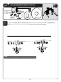
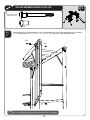
16
SEC
1
SEC
1.1
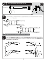
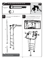
!TTACHTHEPendulums (ARP)TOTHESwing Bar (CB0) USINGTHEHARDWARESHOWN. 0OSITIONTHE7/16” Large Nylon Washers
(ART)BETWEENTHE0ENDULUM ANDTHEBRACKETSDo this for each set of brackets on the Swing Bar.
ARR
ARPX
.OTACTUALSIZE
ARQX
ARRX
ARR
ARQ
ARQ
ARP
ARP
ARSX ARTX
ART
ART
ART
ART
ARS
ARS
ARS
ARS
CBO
11/16”
1/4”
Note: Do not overtighten the hardware. Pendulums should pivot on Bolt (ARQ).
!

TOOLS AND HARDWARE REQUIRED FOR THIS PAGE
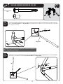
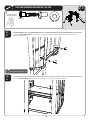
17
SEC
1
SEC
1.2
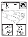
!TTACHANA-Frame Pole (CBG)TOTHESwing Bar (CBO) INTHELOCATIONINDICATED-AKESURETHEDIMPLEDHOLEFACESAWAYFROM
THE3WING"ARASSHOWN
BZOX
BTSX
3/16”
BTS
BZO
BTS
BZO
SEC
1.3
2EPEATSTEPTOATTACHTHEREMAININGA-Frame Pole (CBG)TOTHESwing Bar (CBO).
CBG
CBO
BTS
BTS
BZO
BZO
CBG
Dimpled Hole
Note: If your A-Frame pole has a dimpled hole, make sure the dimpled hole
faces away from the Swing Bar.
!

TOOLS AND HARDWARE REQUIRED FOR THIS PAGE
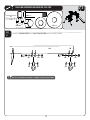
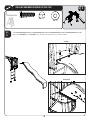
18
SEC
CBI
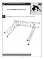
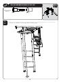
!TTACHTHETurn Bar (CBI)TOTHE!&RAME!SSEMBLYUSINGTHEHARDWARESHOWN
SEC
1.4
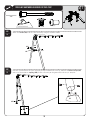
(AVEONEPERSONHOLDTHE!&RAMEASSEMBLYSTEADYASANOTHERLIFTSEACHLEG!TTACHTHEA-Frame Foot Caps (BZJ)
ANDSECURETHEMWITHTHECap Plugs (BZK)2ESTTHEASSEMBLYONTHEGROUNDONCETHISSTEPISCOMPLETE
SEC
1.5
1
BZJX
BZKX
NOTACTUALSIZE
BZK
BZK
BZJ
BZOX
BTSX
3/16”
BZO
BZO
BTS
BTS
BZK
BZK
BZJ

19
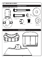
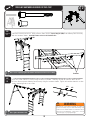
MONKEY BARS ASSEMBLY
HARDWARE REQUIRED
SEC
2
MONKEY BARS ASSEMBLY HARDWARE BAG [CVH]
Hardware shown at Actual Size
ARPX
Pendulum
ARQX
vXv"UTTON
(EAD"OLT
ARSX
v3MALL
.YLON7ASHER
ARTX
v,ARGE.YLON7ASHER
BZOX
vXv3HOULDER"OLT
BTSX
v"ARREL.UT
BZKX
v#AP0LUG
ARRX
v!CORN.UT
CSBX
2OUND&OOT#AP
CSAX
3ADDLE#AP
CSDX
%ND#AP
PARTS REQUIRED
Parts shown at Actual Size

20
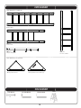
PARTS REQUIRED
Parts shown at 5% of actual size
TOOLS REQUIRED
3/16” Allen Wrench
INCLUDED
CRPX
-ONKEY"ARS'USSET
CRRX
4RAPEZE3WING"AR
CRXX
&IRE0OLE,ADDER
CRYX
3LIDE,ADDER
CSCX
-ONKEY"ARS
Parts shown at 10% of actual size
Ladder
1/4” Allen Wrench
INCLUDED
11/16” Wrench
CWVX
-ONKEY"ARS'USSETWITH,OGO
La page charge ...
La page charge ...
La page charge ...
La page charge ...
La page charge ...
La page charge ...
La page charge ...
La page charge ...
La page charge ...
La page charge ...
La page charge ...
La page charge ...
La page charge ...
La page charge ...
La page charge ...
La page charge ...
La page charge ...
La page charge ...
La page charge ...
La page charge ...
-
 1
1
-
 2
2
-
 3
3
-
 4
4
-
 5
5
-
 6
6
-
 7
7
-
 8
8
-
 9
9
-
 10
10
-
 11
11
-
 12
12
-
 13
13
-
 14
14
-
 15
15
-
 16
16
-
 17
17
-
 18
18
-
 19
19
-
 20
20
-
 21
21
-
 22
22
-
 23
23
-
 24
24
-
 25
25
-
 26
26
-
 27
27
-
 28
28
-
 29
29
-
 30
30
-
 31
31
-
 32
32
-
 33
33
-
 34
34
-
 35
35
-
 36
36
-
 37
37
-
 38
38
-
 39
39
-
 40
40


Lifetime 90143 Le manuel du propriétaire
- Taper
- Le manuel du propriétaire
dans d''autres langues
- English: Lifetime 90143 Owner's manual