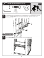
Lifetime 90177 Le manuel du propriétaire
- Taper
- Le manuel du propriétaire

1
Keep this Product ID Number and use when contacting Customer Service:
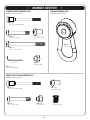
MODEL N° 90177
OWNER’S MANUAL
COPY

2
INSTRUCTION #1174493
03/17/2016
REGISTER YOUR PRODUCT ONLINE AT WWW.LIFETIME.COM
LIFETIME’S PROMISE TO YOU:
We invite you to read our privacy policy at www.lifetime.com
REGISTER today!
At Lifetime
®
, we are committed to providing innovative and quality products. While registering, you will have the opportunity to give us your feedback. Your
input is valuable to us.
• You can also opt in to receive new product notifi cations or promotions.
• In the unlikely event of a product recall or safety modifi cation, your registration provides the information we need to notify you
directly.
• Registration is fast, easy, and completely voluntary.
Maintaining your privacy is our long-standing policy at Lifetime
®
. And you can rest assured that Lifetime
®
will not sell or provide
your personal data to other third parties, or allow them to use your personal data for their own purposes.
Most injuries are caused by misuse and/or not following instructions. Use caution when using this product.
To ensure safety, do not attempt to assemble this product without reading and following all instructions carefully. Check the entire
box and inside all packing materials for parts and/or additional instruction material. Before beginning assembly, identify and inventory
all parts and hardware using the parts and hardware lists and identifi ers in this document. Proper and complete assembly, use and
supervision are essential for proper orientation and to reduce the risk of accident or injury. A high probability of serious injury exists
if this product is not installed, maintained, and/or operated properly. Failure to comply with any of the warnings in this instruction
manual may result in serious personal injuries such as cuts, broken bones, nerve damage, paralysis, brain injury, or death. Failure to
comply may also result in property damage. Please heed all warnings and cautions.
FAILURE TO FOLLOW THESE WARNINGS MAY RESULT IN SERIOUS INJURY OR PROPERTY
DAMAGE AND WILL VOID WARRANTY.
SAFETY INSTRUCTIONS
Save this owner’s manual for future reference and in the event that the manufacturer has to be contacted.
**U.S. and Canada customers ONLY**
FOR CUSTOMERS OUTSIDE THE U.S. OR CANADA, PLEASE CONTACT
THE STORE FOR ASSISTANCE.
DO NOT CONTACT THE STORE!
CALL OUR CUSTOMER SERVICE DEPARTMENT at
1 (800) 225-3865
HOURS: 7:00 a.m. to 5:00 p.m. Monday through Friday (MST)
9:00 a.m. to 1:00 p.m. Saturday (MST)
Questions or Missing Parts?
ID:
TO SAVE TIME WHEN CONTACTING CUSTOMER SERVICE, PLEASE HAVE THE PRODUCT ID AVAILABLE BEFORE YOU CALL; IT’S LOCATED AT THE BOTTOM-LEFT CORNER
OF THE FRONT PAGE OF THIS MANUAL.
This product is intended for use by children from ages 3 to 12,
and is for outdoor residential use only.
COPY

3
BEFORE BEGINNING ASSEMBLY
Keep the hardware bags and their contents separate. If any parts are missing, call our
Customer Service Department.
Identify and inventory all parts and hardware using the parts and hardware lists and
identifi ers in this document.
Test fi t all Bolts by inserting them into their respective holes. If necessary, carefully
scrape away any excess powder coating buildup from inside the holes. Do not scrape
away all of the powder coating. Bare metal may rust. You may need to pound some
Bolts into place with a hammer or mallet.
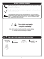
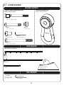
TOOLS AND PARTS REQUIRED FOR THIS ASSEMBLY
*Two adults required to
complete assembly*
Only adults should set up the product. Do not allow children
in the setup area until assembly is complete.
3/16” Allen Wrench
(2, included)
1/2” Wrench
(2)
Phillips Screwdriver
(1)
Ladder
(1)
Rubber Mallet

4
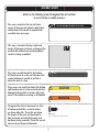
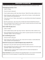
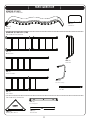
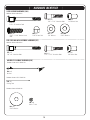
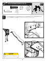
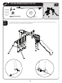
This area is located at the top, left-hand
corner of the page and indicates which tools
and hardware are needed to complete the
assembly steps on a page.
This area is located at the top, right-hand
corner of the page and shows an image of the
product with shaded parts indicating which
section is being assembled.
SEC
#
Note:
!
Refer to the following areas throughout the instructions
to assist in the assembly process:
This area is usually located in the bottom,
left-hand corner of a step and indicates that
special attention is needed to perform a
particular part of a step.
These areas are usually located in the bottom,
right-hand corner of a step and indicate that
damage to the product or serious injury may
occur if the caution or warning is not heeded.
Throughout the Parts & Hardware List, Part
& Hardware Identifi ers, and instructions
are three-letter IDs. These IDs are below
the images of the parts and hardware to
help you locate and identify the parts and
hardware during assembly. These IDs are not
necessarily on the parts themselves.
WARNING
ASSEMBLY GUIDES
TOOLS AND HARDWARE REQUIRED FOR THIS PAGE
CAUTION
ADZ (x10)
1/4” x 5/8” Pan-Head Screw

5
**IMPORTANT SAFETY INFORMATION**
PLEASE READ BEFORE
BEGINNING ASSEMBLY:
• Place the equipment on a level, well-drained ground, not less than 6 ft (1.8 m) from any structure or obstruc-
tion such as a fence, garage, or house.
• Provide enough room so that children can use the equipment safely. For example, for structures with multiple
play activities, a slide should not exit in front of a swing.
• Separate active and quiet activities from each other. For example, locate sandboxes away from swings or use
a guardrail or barrier to separate the sandbox from the movement of the swings.
• Do not install home playground equipment over concrete, asphalt, packed earth, grass, carpet, or any other
hard surface. A fall onto a hard surface can result in serious injury to the equipment user (see page 7).
• To prevent serious injury, warn children that they must not use the equipment until properly installed.
• Create a site free of obstacles that could cause injuries – such as low overhanging tree branches, overhead
wires, tree stumps and/or roots, large rocks, bricks, and concrete.
• Choose a level location for the equipment. This can reduce the likelihood of the play set tipping over and
loose-fill surfacing materials washing away during heavy rains.
• Tighten bolts securely, tighten nuts on bolts flush to the tube or member, and place caps over exposed bolts
snug to the nut.
• For any questions call our Customer Service Department at 1-800-225-3865 for more information.
• Use containment, such as digging out around the perimeter and/or lining the perimeter with landscape edging.
• Do not install loose fill surfacing over hard surfaces such as concrete or asphalt.
• Installations of rubber tiles or poured-in-place surfaces (other than loose-fill materials) generally require a
professional and are not “do-it yourself” projects.
• Use Playground Surfacing Materials (other than loose-fill material) which comply to the safety standard ASTM F1292
Standard Specification for Impact Attenuation of Surfacing Materials within the Use Zone of Playground Equipment.
INSTALLATION & GROUND PREPARATION INSTRUCTIONS
PLAYGROUND AND SURFACE MATERIALS INSTRUCTIONS

6
OPERATING INSTRUCTIONS
Observing the following instructions and warnings reduces the likelihood of serious or fatal injury:
• The maximum number of occupants that may safely use the entire play set including all components is six
with a maximum weight of 640 pounds
(290 kg).
• On-site adult supervision should be provided for children of all ages.
• Instruct children not to walk close to, in front of, behind, or between moving items.
• Do not move the equipment while it is in use.
• Instruct children not to twist swing chains or ropes or loop them over the top support bar since this may
reduce the strength of the chain or rope.
• Instruct children to avoid swinging empty seats.
• Teach children to sit in the center of the swings with their full weight on the seats.
• Instruct children not to use the equipment in a manner other than intended.
• Instruct children not to get off the equipment while it is in motion.
• To prevent entanglement and strangulation, dress children appropriately using well-fitting shoes and avoiding
ponchos, scarves, jackets with neck drawstrings, helmets with straps, and other loose-fitting clothing that is
potentially hazardous while using equipment.
• Instruct children not to play when the equipment is wet.
• Instruct children not to attach items to the playground equipment that are not specifically designed for use
with the equipment, such as, but not limited to, jump ropes, clothesline, pet leashes, cables and chain as
they may cause a strangulation hazard.

7
MAINTENANCE INSTRUCTIONS
If routine checks and maintenance procedures are not done, the equipment could overturn and/or become a hazard.
At the beginning of each play season:
• Tighten all hardware.
• Lubricate all metallic moving parts.
• Check all protective coverings on bolts, pipes, edges and corners. Replace if they are loose, cracked or missing.
• Check all moving parts including swing seats, ropes, cables and chains for wear, rust or other deterioration.
Contact customer service for replacement parts.
• Check metal parts for rust. If found, sand and repaint using a non lead-based paint meeting the requirements
of 16 CFR 1303.
• Reinstall any plastic parts, such as swing seats or any other items that were removed for the cold season.
• Rake and check depth of loose fill protective surfacing materials to prevent compaction and to maintain appro-
priate depth. Replace as necessary. (See page 5)
Twice a month during play season:
• Tighten all hardware.
• Check all protective coverings on bolts, pipes, edges and corners. Replace if they are loose, cracked or missing.
• Rake and check depth of loose fill protective surfacing materials to prevent compaction and to maintain appro-
priate depth. Replace as necessary. (See page 5)
Once a month during play season:
• Lubricate all metallic moving parts.
• Check all moving parts including swing seats, ropes, cables and chains for wear, rust or other deterioration.
Contact customer service for replacement parts.
At the end of each play season or when the temperature drops below 40
o
F (5
o
C):
• Remove plastic swing seats and the trapeze swing and take them indoors or do not use.
• Rake and check depth of loose fill protective surfacing materials to prevent compaction and to maintain appro-
priate depth. Replace as necessary. (See page 5)
• If the warning sticker is illegible, destroyed, or removed contact the Customer Service Department at
1-800-225-3865 for a replacement.
Disposal Instructions: Disassemble and dispose of the playground equipment in such a way that no unreasonable
hazards will exist at the time the equipment is discarded. Follow all local disposal requirements.

8
The U.S. Consumer Product Safety Commission (CPSC)
estimates that about 100,000 playground equipment re-
lated injuries resulting from falls to the ground surface are
treated annually in U.S. hospital emergency rooms. Injuries
involving this hazard pattern tend to be among the most
serious of all playground injuries, and have the potential
to be fatal, particularly when the injury is to the head. The
surface under and around playground equipment can be a
major factor in determining the injury causing potential of a
fall. It is self evident that a fall onto a shock-absorbing sur-
face is less likely to cause a serious injury than a fall onto a
hard surface. Playground equipment should never be placed
on hard surfaces such as concrete or asphalt and while
grass may appear to be acceptable, it may quickly turn to
hard packed earth in areas of high traffic. Shredded bark
mulch, wood chips, fine sand or fine gravel are considered
to be acceptable shock-absorbing surfaces when installed
and maintained at a sufficient depth under and around
playground equipment.
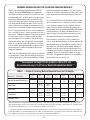
Table 1 lists the maximum height from which a child would
not be expected to sustain a life-threatening head injury in
a fall onto different loose-fill surfacing materials if they are
installed and maintained at depths of 6, 9, and 12 inches.
However, it should be recognized that all injuries due to falls
cannot be prevented no matter what surfacing material is
used.
It is recommended that a shock-absorbing material should
extend a minimum of 6 ft. in all directions from the perim-
eter of stationary equipment such as climbers and slides.
However, because children may deliberately jump from a
moving swing, the shock absorbing material should extend
in the front and rear of a swing a minimum distance of 2
times the height of the pivot point measured from a point
directly beneath the pivot on the supporting structure.
This information is intended to assist in comparing the
relative shock-absorbing properties of various materials. No
particular material is recommended over another. However,
each material is only effective when properly maintained.
Materials should be checked periodically and replenished
to maintain correct depth as determined necessary for your
equipment. The choice of a material depends on the type
and height of the playground equipment, the availability of
the material in your area, and its cost.
*This information has been extracted from the CPSC publications “Playground Surfacing--Technical Information Guide” and “Handbook for
Public Playground Safety.” Copies of these reports can be obtained by sending a postcard to the: Office of Public Affairs, U.S. Consumer Product
Safety Commission, Washington, D.C., 20207 or call the toll-free hotline: 1-800-638-2772.
***This data is from tests conducted by independent testing laboratories on a 6-inch depth of uncompressed shredded tire samples produced
by four manufacturers. It is recommended that persons seeking to install shredded tires as a protective surface request test data from the sup-
plier showing the critical height of the material when it was tested in accordance with ASTM F1292.
CONSUMER INFORMATION SHEET FOR PLAYGROUND SURFACING MATERIALS*
**The maximum fall height for this product is 108 in (274 cm).
We recommend using 9 in (23 cm) of Double Shredded Bark Mulch.**
5 ft 6 ft 7 ft 9 ft 10 ft 11 ft 12 ft
-- 6 in -- -- 9 in 12 in --
-- 6 in 9 in -- -- -- 12 in
6 in -- 9 in 12 in -- -- --
-- 6 in 9 in -- 12 in -- --
-- -- -- -- 6 in -- --
TABLE 1 — Depth of Surfacing Material Required Based on Fall Heights
Material / Fall Height
Double Shredded Bark Mulch
Wood Chips
Fine Sand
Fine Gravel
Shredded Tires***
(152 cm)
(183 cm) (213 cm)
(274 cm)
(305 cm) (335 cm) (366 cm)
(15 cm)
(23 cm) (30 cm)
(15 cm) (23 cm) (30 cm)
(30 cm)
(23 cm)(15 cm)
(15 cm)
(23 cm)
(30 cm)
(15 cm)

9
A cordless drill can be used for driving screws;
however, care should be taken not to over-tighten or strip screws.
USE AT YOUR OWN RISK!
Safety Zone
USING A DRILL IS NOT RECOMMENDED
FOR DRIVING BOLTS.
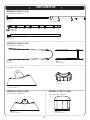
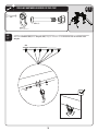
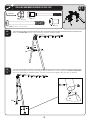
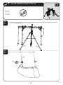
Place the equipment no less than 6 ft. (1.8 m) from any structure or obstruction such as a fence, garage,
house, overhanging branches, laundry lines, or electrical wires. Make sure the clearance in front of and
behind the swings is at least twice the height of the swing bar. The impact surfacing needs to cover the entire
recommended play area. Refer to the example below.
Playset dimensions:
13’ 11” x 18’ 9”
Recommended play area:
25’ 11” x 33’ 7”
25 feet 11 inches
33 feet 7 inches
6 feet
6 feet
6 feet
14 feet 10 inches
14 feet 10 inches
6 feet
6 feet
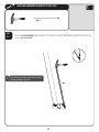
Slide can get hot in direct sunlight. It is not
recommended that a slide be installed facing
south.
CAUTION

10
HARDWARE LIST
PARTS LIST
ID Item Description Qty
PLAYGROUND PARTS
BEK 9’ Slide 1
BEO Slide Deck 1
CVM ADVENTURE SET PARTS KIT 1
CBI Turn Bar 1
CRZ Anchor Rod 1
CRY Slide Ladder 1
CRQ Slide Rail 2
CWV Monkey Bars Gusset 4
CRX Fire Pole Ladder 1
CSC Monkey Bars 1
CRS Fire Pole Hoop 1
CRU Deck Support 1
ID Item Description Qty
CVN ADVENTURE SET PARTS KIT 2
CBG A-Frame Pole 2
CRT Fire Pole 1
CRR Trapeze Swing Bar 1
CBO Swing Bar 1
CVO ADVENTURE SET PARTS KIT 3
BKT Belt Swing 3
BKU Trapeze Swing 1
CSA Saddle Cap 4
BZJ Angled Foot Cap 2
EMC ADVENTURE SET PARTS KIT 4
CSB Round Foot Cap 4
EMB ADVENTURE SET PARTS KIT 5
CSD Round End Cap 5
ID Item Description Qty
CAM A-Frame Assembly Hardware
DZP 5/16” - 18 x 3.5” Bolt 2
DZR 5/16” - 18 x 2” Bolt 6
AAN 5/16’’ Cap Nut 8
BTS 1/4” Barrel Nut 6
DSA 1/4” x 3” Shoulder Bolt 6
EEO 3/16” Allen Wrench 2
CVH Monkey Bars Assembly Hardware
BZK .343” Cap Plug 10
DZR 5/16” - 18 x 2” Bolt 2
AAN 5/16’’ Cap Nut 2
BTS 1/4” Barrel Nut 22
DSA 1/4” x 3” Shoulder Bolt 22
CAH Slide Assembly Hardware
BTS 1/4” Barrel Nut 8
DSA 1/4” x 3” Shoulder Bolt 4
DXY 1/4” x 1 1/2” Shoulder Bolt 4
ARX 5/16” x 1 1/4” Button Head Bolt 3
ARM 5/16” Acorn Nut 3
ARL 1/4” Washer 6
CVZ 5/16” Washer 4
CVI Fire Pole Assembly Hardware
BTS 1/4” Barrel Nut 3
DSA 1/4” x 3” Shoulder Bolt 2
DXY 1/4” x 1 1/2” Shoulder Bolt 1
EBX Pendulum Hardware
DZQ Pendulum 8
EMF Anchor Kit Assembly Hardware
EMG Anchor 2
EMH Driving Rod 1
EMI M4 x .7 Nut 8
ENG 5/16” Washer 2

11
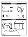
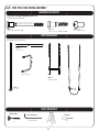
PARTS IDENTIFIER
ADVENTURE SET PARTS KIT 1 [CVM]
Parts shown at 5% of actual size
24”
CRQ (x2)
Slide Rail
BEO (x1)
Slide Deck
CRZ (x1)
Anchor Rod
CRU (x1)
Deck Support
CRS (x1)
Fire Pole Hoop
CRX (x1)
Fire Pole Ladder
CRY (x1)
Slide Ladder
CSC (x1)
Monkey Bars
Parts shown at 10% of actual size
CBI (x1)
Turn Bar
ADVENTURE SET PARTS
Part shown at 5% of actual size
BEK (x1)
9’ Slide
CWV (x4)
Monkey Bars Gusset

12
PARTS IDENTIFIER
ADVENTURE SET PARTS KIT 3 [CVO]
Parts shown at 5% of Actual Size
BKT (x3)
Belt Swing
BKU (x1)
Trapeze Swing
BZJ (x2)
A-Frame Foot Cap
CSB (x4)
Round Foot Cap
CSA (x4)
Saddle Cap
CSD (x5)
Round End Cap
Parts shown at 50% of Actual Size
ADVENTURE SET PARTS KIT 2 [CVN]
Parts shown at 5% of actual size
CBO (x1)
Swing Bar
CBG (x2)
A-Frame Pole
CRR (x1)
Trapeze Swing Bar
CRT (x1)
Fire Pole
ADVENTURE SET PARTS KIT 4 [EMC]
ADVENTURE SET PARTS KIT 5 [EMB]
Parts shown at 50% of Actual Size
Parts shown at 50% of Actual Size

13
HARDWARE IDENTIFIER
MONKEY BARS ASSEMBLY HARDWARE [CVH]
Hardware shown at Actual Size
A-FRAME ASSEMBLY HARDWARE [CAM]
Hardware shown at Actual Size
PENDULUM HARDWARE [EBX]
Hardware shown at Actual Size
DSA (x6)
1/4” x 3” Shoulder Bolt
BTS (x6)
1/4” Barrel Nut
DSA (x22)
1/4” x 3” Shoulder Bolt
BTS (x22)
1/4” Barrel Nut
BZK (x10)
.343” Cap Plug
EEO (x2)
3/16” Allen Wrench
(not to scale)
DZQ (x8)
Pendulum
AAN (x8)
5/16’’ Cap Nut
AAN (x2)
5/16’’ Cap Nut
DZR (x6)
5/16” - 18 x 2” Bolt
DZR (x2)
5/16” - 18 x 2” Bolt
DZP (x2)
5/16” - 18 x 3.5” Bolt

14
HARDWARE IDENTIFIER
SLIDE ASSEMBLY HARDWARE [CAH]
Hardware shown at Actual Size
FIRE POLE AND SWING ASSEMBLY HARDWARE [CVI]
Hardware shown at Actual Size
BTS (x8)
1/4” Barrel Nut
DSA (x4)
1/4” x 3” Shoulder Bolt
DXY (x4)
1/4” x 1 1/2” Shoulder Bolt
ARL (x6)
1/4” Washer
ARX (x3)
5/16” x 1 1/4” Button Head
Bolt
ARM (x3)
5/16” Acorn Nut
DSA (x2)
1/4” x 3” Shoulder Bolt
BTS (x3)
1/4” Barrel Nut
DXY (x1)
1/4” x 1 1/2” Shoulder Bolt
CVZ (x4)
5/16” Washer
ANCHOR KIT ASSEMBLY HARDWARE [EMF]
Hardware shown at 20% Actual Size
EMG (x2)
Anchor
EMH (x1)
Driving Rod
ENG (x2)
5/16” Washer
EMI (x8)
M4 x .7 Nut
Hardware shown at 10% Actual Size
Hardware shown at Actual Size

15
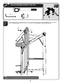
A-FRAME ASSEMBLY
HARDWARE REQUIRED
SEC
1
BZJ (x2)
A-Frame Foot Cap
(not to scale)
TOOLS REQUIRED
PARTS REQUIRED
Parts shown at 5% of Actual Size
3/16” Allen Wrench
CBG (x2)
A-Frame Pole
CB0 (x1)
Swing Bar
CBI (x1)
Turn Bar
1/2” Wrench
(2)
(2, included)
A-FRAME ASSEMBLY HARDWARE BAG [CAM]
Hardware shown at actual size
DSA (x6)
1/4” x 3” Shoulder Bolt
BTS (x6)
1/4” Barrel Nut
EEO (x2)
3/16” Allen Wrench
(not to scale)
DZQ (x6)
Pendulum
AAN (x8)
5/16’’ Cap Nut
DZR (x6)
5/16” - 18 x 2” Bolt
PENDULUM HARDWARE [EBX]
Hardware shown at Actual Size
DZP (x2)
5/16” - 18 x 3.5” Bolt

TOOLS AND HARDWARE REQUIRED FOR THIS PAGE
16
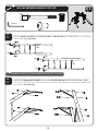
SEC
1
SEC
1.1
3/16”
!
Attach the Pendulums (DZQ) to the Swing Bar (CB0) using the hardware shown.Do this for each set of brackets on the
Swing Bar.
DZQ (x6)
(Not actual size)
AAN (x6) DZR (x6)
AAN
DZR
DZQ
CBO

TOOLS AND HARDWARE REQUIRED FOR THIS PAGE
17
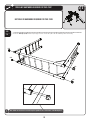
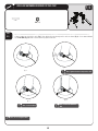
SEC
1
SEC
1.2
Attach an A-Frame Pole (CBG) to the Swing Bar (CBO) in the location indicated.
BTS (x4)
3/16” (x2)
BTS
DSA
BTS
DSA
SEC
1.3
Repeat step 1.2 to attach the remaining A-Frame Pole (CBG) to the Swing Bar (CBO).
CBG
CBO
BTS
BTS
DSA
DSA
CBG
Note: If your A-Frame pole has a dimpled hole, make sure the dimpled hole
faces away from the Swing Bar.
!
DSA (x4)

TOOLS AND HARDWARE REQUIRED FOR THIS PAGE
18
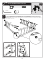
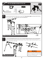
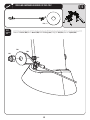
SEC
CBI
Attach the Turn Bar (CBI) to the A-Frame Assembly using the hardware shown.
SEC
1.4
Have one person hold the A-Frame assembly steady as another lifts each leg. Attach the A-Frame Foot Caps (BZJ)
and secure them with the hardware shown. Rest the assembly on the ground once this step is complete.
SEC
1.5
1
DZP
AAN
BZJ
BTS (x2)
3/16” (x2)
DSA
DSA
BTS
BTS
DZP
AAN
BZJ
DSA (x2)
DZP (x2) 5/16” - 18 x 3.5” Bolt
AAN (x2)
5/16’’ Cap Nut

19
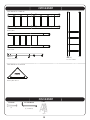
MONKEY BARS ASSEMBLY
HARDWARE REQUIRED
SEC
2
CSB (x4)
Round Foot Cap
CSA (x4)
Saddle Cap
CSD (x5)
End Cap
PARTS REQUIRED
Parts shown at Actual Size
MONKEY BARS ASSEMBLY HARDWARE BAG [CVH]
Hardware shown at Actual Size
DSA (x22)
1/4” x 3” Shoulder Bolt
BTS (x22)
1/4” Barrel Nut
BZK (x10)
.343” Cap Plug
DZQ (x2)
Pendulum
AAN (x2)
5/16’’ Cap Nut
DZR (x2)
5/16” - 18 x 2” Bolt
PENDULUM HARDWARE [EBX]
Hardware shown at Actual Size

20
PARTS REQUIRED
Parts shown at 5% of actual size
TOOLS REQUIRED
(1)
3/16” Allen Wrench
(2, included)
CRR (x1)
Trapeze Swing Bar
CRX (x1)
Fire Pole Ladder
CRY (x1)
Slide Ladder
CSC (x1)
Monkey Bars
Parts shown at 10% of actual size
Ladder
(1)
1/2” Wrench
CWV (x4)
Monkey Bars Gusset
La page charge ...
La page charge ...
La page charge ...
La page charge ...
La page charge ...
La page charge ...
La page charge ...
La page charge ...
La page charge ...
La page charge ...
La page charge ...
La page charge ...
La page charge ...
La page charge ...
La page charge ...
La page charge ...
La page charge ...
La page charge ...
La page charge ...
La page charge ...
La page charge ...
La page charge ...
La page charge ...
La page charge ...
-
 1
1
-
 2
2
-
 3
3
-
 4
4
-
 5
5
-
 6
6
-
 7
7
-
 8
8
-
 9
9
-
 10
10
-
 11
11
-
 12
12
-
 13
13
-
 14
14
-
 15
15
-
 16
16
-
 17
17
-
 18
18
-
 19
19
-
 20
20
-
 21
21
-
 22
22
-
 23
23
-
 24
24
-
 25
25
-
 26
26
-
 27
27
-
 28
28
-
 29
29
-
 30
30
-
 31
31
-
 32
32
-
 33
33
-
 34
34
-
 35
35
-
 36
36
-
 37
37
-
 38
38
-
 39
39
-
 40
40
-
 41
41
-
 42
42
-
 43
43
-
 44
44


Lifetime 90177 Le manuel du propriétaire
- Taper
- Le manuel du propriétaire
dans d''autres langues
- English: Lifetime 90177 Owner's manual
