
Installation guide
Notice d’installation
Guía de instalación

www.fhiaba.com · www.thevettagroup.com · Info Line 1-855-4-FHIABA (1-855-434-4222)

3
www.fhiaba.com · www.thevettagroup.com · Info Line 1-855-4-FHIABA (1-855-434-4222)
1
1.1
1.2
IMPORTANT INSTRUCTIONS
Important safety instructions.....................................................................................................................................
Children safety................................................................................................................................................................
4
4
4
2
2.1
2.2
2.3
2.4
2.5
2.6
2.7
2.8
TECHNICAL REQUIREMENTS
Appliance features and installation requiremens................................................................................................
Installation niche features: Integrated Series.......................................................................................................
Installation niche features: Integrated Series.......................................................................................................
Installation niche features: StandPlus Series.......................................................................................................
Installation niche features: X-Pro Series................................................................................................................
Installation niche features: Classic..........................................................................................................................
Installation niche features: Brilliance-Integrated Series...................................................................................
Installation niche features: Brilliance-Classic.......................................................................................................
4
4
6
7
8
9
10
11
12
3
3.1
3.2
3.3
3.4
PREPARING THE INSTALLATION
Transport to installation site and unpacking.........................................................................................................
Electrical and Water connection................................................................................................................................
Energy: Alternatives and Home Automation.........................................................................................................
Levelling
13
13
13
14
15
4
4.1
4.2
4.3
4.4
4.5
NICHE DIMENSIONS
Niche Dimensions and Installation Styles: Integrated Series..........................................................................
Niche Dimensions and Installation Styles: StandPlus and X-Pro Series......................................................
Flush installation with standard aluminum trims...............................................................................................
Prominent installation with standard aluminum trims......................................................................................
Stand-Proud (for StandPlus and X-Pro series).....................................................................................................
15
15
16
16
16
17
5
5.1
5.2
5.3
5.4
5.5
5.6
5.7
5.8
5.9
5.10
5.11
5.12
PANELS MOUNTING
Decorative door and Bottom-Drawer panels layout............................................................................................
Decorative panels layout for fridge with one bottom-drawer.........................................................................
Decorative panels layout for fridge with two bottom-drawers......................................................................
Decorative panels layout for fridge with glass door and one bottom-drawer..........................................
Decorative panels layout for fridge with glass door and two bottom-drawers........................................
Decorative panels layout for fridge Column.........................................................................................................
Decorative panels layout for fridge column with glass door...........................................................................
Panels Dimensions Single Bottom - Drawer.........................................................................................................
Panels Dimensions Two Bottom - Drawers...........................................................................................................
Panels Dimensions Column Models.........................................................................................................................
Mounting the handles...................................................................................................................................................
Mounting panels to the door and the drawer........................................................................................................
17
17
19
20
21
22
23
24
25
26
27
28
28
6
6.1
6.2
6.3
INSTALLATION
Built-in installation of single appliance...................................................................................................................
Built-in installation of two or more appliances.....................................................................................................
Maximum cabinet depth over “Integrated” refrigerator with single door panel..........................................
30
30
30
32
7
7.1
7.2
7.3
7.4
7.5
COMPLETING THE INSTALLATION
Anti-tipping safety assembly......................................................................................................................................
Mounting the handles on stainless front................................................................................................................
Ventilation........................................................................................................................................................................
Post installation control...............................................................................................................................................
Start Up.............................................................................................................................................................................
33
33
33
35
35
35
INDEX
EN

4
www.fhiaba.com · www.thevettagroup.com · Info Line 1-855-4-FHIABA (1-855-434-4222)
1.1 Important safely instruction
Symbols used in the Guide:
Note
Tips for the correct use of the appliance
Important
Directions to avoid appliance damage
Warning
directions to prevent injury
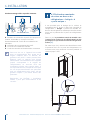
1.2 Children safety
DANGER: Risk of child entrapment. Before you throw
away your old refrigerator or freezer:
> Take o the doors
> Leave the shelves in place so that children may not
easily climb inside.
Important!
Dimensions in parentheses are in inches.
Weights in parentheses are in pounds.
Temperatures in parentheses are
in Fahrenheit degrees.
1. IMPORTANT INSTRUCTIONS
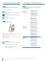
Appliance
dimensions
Integrated
Series 449 / 18”
w: 449 mm (17 5/8”)
h: 2120 mm (83 1/2”)
d: 615 mm (24 1/4”)
Series 599 / 24”
w: 599 mm (23 5/8”)
h: 2120 mm (83 1/2”)
d: 610 mm (24”) /
615 mm (24 1/4”)
Series 749 / 30”
w: 749 mm (29 1/2”)
h: 2120 mm (83 1/2”)
d: 610 mm (24”) /
615 mm (24 1/4”)
Series 899 / 36”
w: 899 mm (35 3/8”)
h: 2120 mm (83 1/2”)
d: 610 mm (24”) /
615 mm (24 1/4”)
Appliance
dimensions
StandPlus
Series 599 / 24”
w: 599 mm (23 5/8”)
h: 2120 mm (83 1/2”)
d: 629 mm (24 3/4”)
Series 749 / 30”
w: 749 mm (29 1/2”)
h: 2120 mm (83 1/2”)
d: 629 mm (24 3/4”)
Series 899 / 36”
w: 899 mm (35 3/8”)
h: 2120 mm (83 1/2”)
d: 629 mm (24 3/4”)
Appliance
dimensions
X-Pro
Series 599 / 24”
w: 599 mm (23 5/8”)
h: 2120 mm (83 1/2”)
d: 635 mm (25”)
Series 749 / 30”
w: 749 mm (29 1/2”)
h: 2120 mm (83 1/2”)
d: 635 mm (25”)
Series 899 / 36”
w: 899 mm (35 3/8”)
h: 2120 mm (83 1/2”)
d: 635 mm (25”)
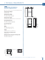
2.1 Appliance features and installation
requirements
2. TECHNICAL REQUIREMENTS

5
www.fhiaba.com · www.thevettagroup.com · Info Line 1-855-4-FHIABA (1-855-434-4222)
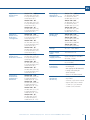
Appliance
dimensions
Classic
Series 599 / 24”
w: 599 mm (23 5/8”)
h: 2120 mm (83 1/2”)
d: 635 mm (25”)
Series 749 / 30”
w: 749 mm (29 1/2”)
h: 2120 mm (83 1/2”)
d: 635 mm (25”)
Series 899 / 36”
w: 899 mm (35 3/8”)
h: 2120 mm (83 1/2”)
d: 635 mm (25”)
Appliance
dimensions
Brilliance
-Integrated
Series 599 / 24”
w: 599 mm (23 5/8”)
h: 2120 mm (83 1/2”)
d: 610 mm (24”)
Series 749 / 30”
w: 749 mm (29 1/2”)
h: 2120 mm (83 1/2”)
d: 610 mm (24”)
Series 899 / 36”
w: 899 mm (35 3/8”)
h: 2120 mm (83 1/2”)
d: 610 mm (24”)
Appliance
dimensions
Brilliance-Classic
Series 599 / 24”
w: 599 mm (23 5/8”)
h: 2120 mm (83 1/2”)
d: 635 mm (25”)
Series 749 / 30”
w: 749 mm (29 1/2”)
h: 2120 mm (83 1/2”)
d: 635 mm (25”)
Series 899 / 36”
w: 899 mm (35 3/8”)
h: 2120 mm (83 1/2”)
d: 635 mm (25”)
Packaging
dimensions
Integrated /
Brilliance
Series 449 / 18”
w: 650 mm (25 5/8”)
h: 2260 mm (89”)
d: 800 mm (31 1/2”)
Series 599 / 24”
w: 650 mm (25 5/8”)
h: 2260 mm (89”)
d: 800 mm (31 1/2”)
Series 749 / 30”
w: 800 mm (31 1/2”)
h: 2260 mm (89”)
d: 800 mm (31 1/2”)
Series 899 / 36”
w: 950 mm (37,4”)
h: 2260 mm (89”)
d: 800 mm (31 1/2”)
Packaging
dimensions
StandPlus / X-Pro
Series 599 / 24”
w: 650 mm (25 5/8”)
h: 2260 mm (89”)
d: 800 mm (31 1/2”)
Series 749 / 30”
w: 800 mm (31 1/2”)
h: 2260 mm (89”)
d: 800 mm (31 1/2”)
Series 899 / 36”
w: 950 mm (37 3/8”)
h: 2260 mm (89”)
d: 800 mm (31 1/2”)
Weight with
packaging
Series 449 / 18”
up to 170 kg (375 lb)
Series 599 / 24”
up to 200 kg (441 lb)
Series 749 / 30”
up to 220 kg (485 lb)
Series 899 / 36”
up to 240 kg (529 lb)
Voltage AC 110 - 120V 60Hz
Power supply
cable
90° Nema 5-15P
Potable water
supply pressure
from 0.05 MPa to 0.5 MPa
(0.5 Bar - 5 Bar)
Water connection 3/4” NPT (1/4” elbow adap-
ter included)
Provided
installation
accessories
- Customized panels
mounting Kit
- Anti-tipping Kit (B04000200)
- Lateral connecting kit
(KCLIT/KCLIH)
- 4 mm (1/8”) allen wrench
Additional
equipment
necessary
- Phillips head screwdriver
- wood drill
- 2.5 mm (1/8”) bit for wood
- 8 mm (3/8”) bit for walls
- 17 mm (11/16”) wrench
- 19 mm (3/4”) wrench
EN

6
www.fhiaba.com · www.thevettagroup.com · Info Line 1-855-4-FHIABA (1-855-434-4222)
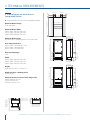
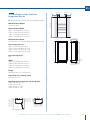
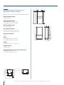
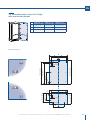
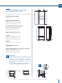
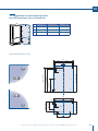
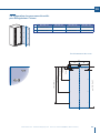
2.2 Installation niche features:
Integrated Series
A - area to be left clear for the anti-tipping brackets
Minimum Niche Height
2134 mm (84”)
Minimum Niche Width
S899 / FI36: 902 mm (35 1/2”)
S749 / FI30: 752 mm (29 5/8”)
S599 / FI24: 602 mm (23 3/4”)
Minimum Niche Depth
610 mm (24”) + panel thickness for flush install
Door Swing Clearance
S899 / FI36: 1470 mm (57 7/8”)
S749 / FI30: 1320 mm (52”)
S599 / FI24: 1170 mm (46”)
Door Opening Angle
105°
Width
S899 / FI36: 899 mm (35 3/8”)
S899 / FI36: 749 mm (29 1/2”)
S899 / FI36: 599 mm (23 5/8”)
Height
2120 mm (83 1/2”) + 25 mm (1”)
Depth with door (without panel)
610 mm (24”)
Minimum distance from the wall (hinge side)
S899: 160 mm (6 1/4”)
S749: 125 mm (5”)
S599: 90 mm (3 1/2”)
2. TECHNICAL REQUIREMENTS
248 (9
¾”
)
+ 25 (1”)
330
(13”)
259
(10
¼”
)
min 2134 (84”)
A A
140 (5 ½”) 140 (5 ½”)
100 (4”)
100 (4”)
S899 / FI36: 902 (35 ½”)
S599 /FI24: 602 (23 ¾”)
S749 / FI30: 752 (29 ⅝”)
610 (24”)
560 (22”)
610 (24”)
560 (22”)
1293 (50 ⅞” )
474
(18 ⅝”)
231 (9
⅛”
) +
25 (1”)
500 (19 ¾”)
500 (19 ¾”)
248 (9
¾”
)
+ 25 (1”)
231 (9
⅛”
) +
25 (1”)
20 (¾”)
20 (¾”)10 (⅜”)
721 (28 ⅜”) +25 (1”)
2120 (83 ½”) +25 (1”)
846 (33 ¼”) +25 (1”)
2120 (83 ½”) +25 (1”)
1168(46”)
105°
560 (22”)
610 (24”)
899 / FI36: 899 (35 ⅜”)
749 / FI30: 749 (29 ½”)
599 / FI24: 599 (23 ⅝”)
10 (⅜”)
992 (39”)
899 / FI36: 1470 (57 ⅞”)
749 / FI30: 1320 (52”)
599 / FI24: 1170 (46”)
899 / FI36: 160 (6 ¼”)
749 / FI30: 125 (5”)
599 / FI24: 90 (3 ½”)

7
www.fhiaba.com · www.thevettagroup.com · Info Line 1-855-4-FHIABA (1-855-434-4222)
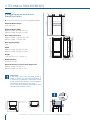
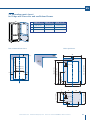
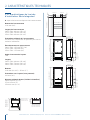
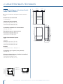
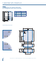
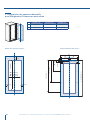
2.3 Installation niche features:
Integrated Series
A - area to be left clear for the anti-tipping brackets
Minimum Niche Height
2134 mm (84”)
Minimum Niche Width
S899 / FI36: 902 mm (35 1/2”)
S749 / FI30: 752 mm (29 5/8”)
S599 / FI24: 602 mm (23 3/4”)
S449 / FI18: 452 mm (17 3/4”)
Minimum Niche Depth
615 mm (24 1/4”) + panel thickness for flush install
Door Swing Clearance
S899 / FI36: 1475 mm (58”)
S749 / FI30: 1325 mm (52 1/8”)
S599 / FI24: 1175 mm (46 1/4”)
S449 / FI18: 1025 mm (40 3/8”)
Door Opening Angle
105°
Width
S899 / FI36: 899 mm (35 3/8”)
S749 / FI30: 749 mm (29 1/2”)
S599 / FI24: 599 mm (23 5/8”)
S449 / FI18: 449 mm (17 5/8”)
Height
2120 mm (83 1/2”) + 25 mm (1”)
Depth with door (without panel)
615 mm (24 1/4”)
Minimum distance from the wall (hinge side)
S899: 160 mm (6 1/4”)
S749: 125 mm (5”)
S599: 90 mm (3 1/2”)
S449: 50 mm (1 7/8”)
EN
233 (9
¼”
)
+ 25 (1”)
min 2134 (84”)
A A
140 (5 ½”) 140 (5 ½”)
100 (4”)
100 (4”)
S899 / FI36: 902 (35 ½”)
S449 / FI18: 452 (17 ¾”)
S599 / FI24: 602 (23 ¾”)
S749 / FI30: 752 (29 ⅝”)
615 (24 ¼”)
565 (22 ¼” )
1808 (71 ¼” )
231 (9
⅛”
) +
25 (1”)
505 (19 ¾”)
2120 (83 ½”) +25 (1”)
105°
S899 / FI36: 1475 (58”)
S749 / FI30: 1325 (52 ⅛”)
S599 / FI24: 1175 (46 ¼”)
S449 / FI18: 1025 (40
⅜
”)
565 (22 ¼”)
615 (24 ¼”)
S899 / FI36: 899 (35 ⅜”)
S749 / FI30: 749 (29 ½”)
S599 / FI24: 599 (23 ⅝”)
S449 / FI18: 449 (17 ⅝”)
10 (⅜”)
S899 / FI36: 160 (6 ¼”)
S749 / FI30: 125 (5”)
S599 / FI24: 90 (3 ½”)
S449 / FI18: 50 (1
⅞
”)

8
www.fhiaba.com · www.thevettagroup.com · Info Line 1-855-4-FHIABA (1-855-434-4222)
2. TECHNICAL REQUIREMENTS
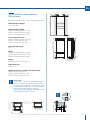
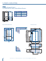
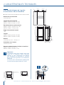
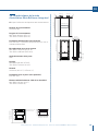
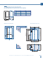
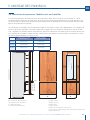
2.4 Installation niche features:
StandPlus Series
A - area to be left clear for the anti-tipping brackets
Minimum Niche Height
2134 mm (84”)
Minimum Niche Width
MS899 / FM36: 902 mm (35 1/2”)
MS599 / FM24: 602 mm (23 3/4”)
Door Swing Clearance
MS899 / FM36: 1470 mm (57 7/8”)
MS599 / FM24: 1170 mm (46”)
Door Opening Angle
105°
Width
MS899 / FM36: 899 mm (35 3/8”)
MS599 / FM24: 599 mm (23 5/8”)
Height
2120 mm (83 1/2”) + 25 mm (1”)
Depth with door
629 mm (24 3/4”)
Minimum distance from the wall (hinge side)
MS899 / FM36: 230 mm (9”)
MS599 / FM24: 160 mm (6 1/4”)
Important!
If the units are to be installed inside a
niche or within an enclosed structure, it
is necessary to design a ventilation shaft
at the back of the niche to assure proper
ventilation at the back of the unit.
Cross-sectional chimney ventilation area
should equal 200cm² (31in²)
A A
140 (5 ½”) 140 (5 ½”)
100 (4”)
100 (4”)
min 2134 (84”)
MS899 / FM36: 902 (35 ½”)
MS599 / FM24: 602 (23 ¾”)
560 (22”)
2120 (83 ½”) +25 (1”)
613 (24 ⅛”)+25 (1”)
629 (24 ¾”)
615 (24 ¼”)
666 (26 ¼”)
485 (19 ⅛”)
1296 (50”)
195 (7 ⅝”)
8 (⅜”)
8 (⅜”)
128 (5)
+ 25 (1”)
min 10 (⅜”)
min 50 (2”)
105°
1010 (39 ¾”)
560 (22”)
MS899 / FM36: 899 (35 ⅜”)
MS599 / FM24: 599 (23 ⅝”)
10 (⅜”)
629 (24 ¾”)
37 (1 ½”)
69 (2 ¾”)
MS899 / FM36: 1470 (57 ⅞”)
MS599 / FM24: 1170 (46”)
MS899 / FM36: 230 (9”)
MS599 / FM24: 160 (6 ¼”)

9
www.fhiaba.com · www.thevettagroup.com · Info Line 1-855-4-FHIABA (1-855-434-4222)
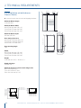
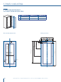
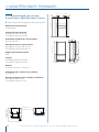
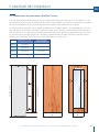
2.5 Installation niche features:
X-Pro Series
A - area to be left clear for the anti-tipping brackets
Minimum Niche Height
2134 mm (84”)
Minimum Niche Width
XS899 / FP36: 902 mm (35 1/2”)
XS749 / FP30: 752 mm (29 5/8”)
XS599 / FP24: 602 mm (23 3/4”)
Door Swing Clearance
XS899 / FP36: 1470 mm (57 7/8”)
XS749 / FP30: 1320 mm (52”)
XS599 / FP24: 1170 mm (46”)
Door Opening Angle
105°
Width
XS899 / FP36: 899 mm (35 3/8”)
XS749 / FP30: 749 mm (29 1/2”)
XS599 / FP24: 599 mm (23 5/8”)
Height
2120 mm (83 1/2”) + 25 mm (1”)
Depth with door
635 mm (25 ”)
Minimum distance from the wall (hinge side)
XS899 / FP36: 230 mm (9”)
XS749 / FP30: 195 mm (7 3/4”)
XS599 / FP24: 160 mm (6 1/4”)
Important!
If the units are to be installed inside a
niche or within an enclosed structure, it
is necessary to design a ventilation shaft
at the back of the niche to assure proper
ventilation at the back of the unit.
Cross-sectional chimney ventilation area
should equal 200cm² (31in²)
EN
A A
140 (5 ½”) 140 (5 ½”)
100 (4”)
100 (4”)
min 2134 (84”)
XS899 / FP36: 902 (35 ½”)
XS599 /FP24: 602 (23 ¾”)
XS749 / FP30: 752 (29 ⅝”)
560 (22”)
2120 (83 ½”) +25 (1”)
613 (24 ⅛”)+25 (1”)
635 (25”)
693 (27 ¼”)
516 (20 ⅜”)
1296 (50”)
195 (7 ⅝”)
8 (⅜”)
8 (⅜”)
97 (3 ⅞”)
+ 25 (1”)
1016 (40”)
XS899 / FP36: 1470 (57 ⅞”)
XS749 / FP30: 1320 (52”)
XS599 / FP24: 1170 (46”)
560 (22”)
75 (3”)
XS899 / FP36: 899 (35 ⅝”)
XS749 / FP30: 749 (29 ½”)
XS599 / FP24: 599 (23 ⅝”)
10 (⅜”)
58 (2 ¼”)
105°
635 (25”)
XS899 / FP36: 230 (9”)
XS749 / FP30: 195 (7 ¾”)
XS599 / FP24: 160 (6 ¼”)
min 10 (⅜”)
min 50 (2”)

10
www.fhiaba.com · www.thevettagroup.com · Info Line 1-855-4-FHIABA (1-855-434-4222)
2. TECHNICAL REQUIREMENTS
2.6 Installation niche features:
Classic Series
A - area to be left clear for the anti-tipping brackets
Minimum Niche Height
2134 mm (84”)
Minimum Niche Width
899 / FK36: 902 mm (35 1/2”)
749 / FK30: 752 mm (29 5/8”)
599 / FK24: 602 mm (23 3/4”)
Minimum Niche Depth
650 mm (25 5/8”)
Door Swing Clearance
899 / FK36: 1470 mm (56 1/2”)
749 / FK30: 1320 mm (50 5/8”)
599 / FK24: 1170 mm (46”)
Door Opening Angle
105°
Width
899 / FK36: 899 mm (35 3/8”)
749 / FK30: 749 mm (29 1/2”)
599 / FK24: 599 mm (23 5/8”)
Height
2120 mm (83 1/2”) + 25 mm (1”)
Depth with door
635 mm (25 ”)
Minimum distance from the wall (hinge side)
899 / 36: 230 mm (9”)
749 / 30: 195 mm (7 3/4”)
599 /24: 160 mm (6 1/4”)
A A
140 (5 ½”) 140 (5 ½”)
100 (4”)
100 (4”)
min 2134 (84”)
899 / FK36: 902 (35 ½”)
749 / FK30: 752 (29 ⅝”)
2120 (83 ½”) +25 (1”)
732 (28 ⅞”)+25 (1”)
599 / FK24: 602 (23 ¾”)
560 (22”)
693 (27 ¼”)
45 (1 ¾”)
1378 (54 ¼”)
9 ( ⅜”)
637 (25 ⁄”)
96 (3 ¾”)
635 (25”)
105°
899 / FK36: 1470 (57 ⅞”)
749 / FK30: 1320 (52”)
599 / FK24: 1170 (46”)
560 (22”)
635 (25”)
899 / FK36: 899 (35 ⅜”)
749 / FK30: 749 (29 ½”)
599 / FK24: 599 (23 ⅝”)
10 (⅜”)
75 (3”)
58 (2 ¼”)
899 / FK36: 230 (9”)
749 / FK30: 195 (7 ¾”)
599 / FK24: 160 (6 ¼”)
1016 (40”)

11
www.fhiaba.com · www.thevettagroup.com · Info Line 1-855-4-FHIABA (1-855-434-4222)
2.7 Installation niche features:
Brilliance-Integrated Series
A - area to be left clear for the anti-tipping brackets
Minimum Niche Height
2134 mm (84”)
Minimum Niche Width
899 / BI36: 902 mm (35 1/2”)
749 / BI30: 752 mm (29 5/8”)
Minimum Niche Depth
610 mm (24”) + panel thickness for flush install
Door Swing Clearance
899 /BI36: 1435 mm (56 1/2” in)
749 / BI30: 1285 mm (50 5/8” in)
Door Opening Angle
105°
Width
899 /BI36: 899 mm (35 3/8”)
749 / BI30: 749 mm (29 1/2”)
Height
2120 mm (83 1/2”) + 25 mm (1”)
Depth with door (without panel)
610 mm (24”)
Minimum distance from the wall (hinge side)
899 /BI36: 160 mm (6 1/4”)
749 / BI30: 125 mm (5”)
2. TECHNICAL REQUIREMENTS
EN
105°
560 (22”)
610 (24”)
899 / BI36: 899 (35 ⅜”)
749 / BI30: 749 (29 ½”)
10 (⅜”)
992 (39”)
899 / BI36: 1470 (57 ⅞”)
749 / BI30: 1320 (52”)
899 / BI36: 160 (6 ¼”)
749 / BI30: 125 (5”)
A A
140 (5 ½”) 140 (5 ½”)
100 (4”)
100 (4”)
min 2064 (81 ¼”)
899 / BI36: 902 (35 ½”)
749 / BI30: 752 (29 ⅝”)
610 (24”)
560 (22”)
1293 (50 ⅞” )
474
(18 ⅝”)
231 (9
⅛”
) +
25 (1”)
500 (19 ¾”)
248 (9
¾”
)
+ 25 (1”)
20 (¾”)
721 (28 ⅜”) +25 (1”)
2120 (83 ½”) +25 (1”)

12
www.fhiaba.com · www.thevettagroup.com · Info Line 1-855-4-FHIABA (1-855-434-4222)
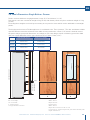
2.8 Installation niche features:
Brilliance-Classic Series
A - area to be left clear for the anti-tipping brackets
Minimum Niche Height
2134 mm (84”)
Minimum Niche Width
899 / BKI36: 902 mm (35 1/2”)
749 / BKI30: 752 mm (29 5/8”)
Minimum Niche Depth
650 mm (25 5/8”)
Door Swing Clearance
899 / BKI36: 14 mm (56 1/2” in)
749 / BKI30: 1285 mm (50 5/8” in)
Door Opening Angle
105°
Width
899 / BKI36: 899 mm (35 3/8”)
749 / BKI30: 749 mm (29 1/2”)
Height
2120 mm (83 1/2”) + 25 mm (1”)
Depth with door
635 mm (25 ”)
Minimum distance from the wall (hinge side)
899 / BKI36: 230 mm (9”)
749 / BKI30: 195 mm (7 3/4”)
A A
140 (5 ½”) 140 (5 ½”)
100 (4”)
100 (4”)
min 2134 (84”)
899 / BKI36: 902 (35 ½”)
749 / BKI30: 752 (29 ⅝”)
2120 (83 ½”) +25 (1”)
635 (25”)
560 (22”)
693 (27 ¼”)
1378 (54 ¼”)587 (23 ⅛”)
146 (5 ¾”)
+ 25(1”)
9 ( ⅜”)
732 (28 ⅞”)+25 (1”)
105°
899 / FK36: 1470 (57 ⅞”)
749 / FK30: 1320 (52”)
560 (22”)
635 (25”)
899 / FK36: 899 (35 ⅜”)
749 / FK30: 749 (29 ½”)
10 (⅜”)
75 (3”)
58 (2 ¼”)
899 / FK36: 230 (9”)
749 / FK30: 195 (7 ¾”)
1016 (40”)

13
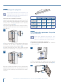
www.fhiaba.com · www.thevettagroup.com · Info Line 1-855-4-FHIABA (1-855-434-4222)
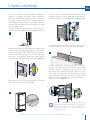
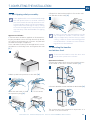
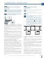
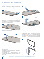
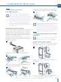
3.1 Transport to installation site
and unpacking
The appliance is very heavy.
Take maximum care during handling
to avoid injury.
The appliance should always be
transported in an erect position.
Avoid at all costs leaning it on its front
side.
Since this is a large and heavy appliance, before trans-
porting the appliance, check the access to the loca-
tion where it will be installed (door size, manoeuvring
space in stairwells, etc.).
The appliance is attached to the base of the packaging
(pallet) through four bolts which can be removed us-
ing a 19 mm (3/4”) wrench.
It is recommended to use a manual transporting de-
vice to move the appliance to the installation site, and
only at this point to remove the base of the packaging.
The appliance should always be transported in an
erect position.
If this is not possible, transport the appliance laying
on its rear side.
Once at the installation site, the appliance, which is
equipped with four wheels, can be taken o the pallet
and positioned in the installation area.
Operate as follows:
> Take o the four boltshsecuring [ 1 ] the appliance to
the pallet by means of a 19 mm (3/4”) wrench or socket.
> Remove the fixing brackets [ 3 ] and [ 4 ] .
> To release the front fixing bracket [ 3 ] , unscrew the
rear wheel adjusting bolt [ 2 ] by means of a 13 mm
(1/2”) wrench or socket. Avoid straining this bolt at its
stop points one way or the other so as to not damage
the rear leveling system.
Ensure the front leveling legs are retracted so that all
4 wheels are able to contact the floor for easiest ma-
neuvering.
> From the back of the unit and by means of a suit-
able, high duty hand trolley, take o the appliance and
place it on the floor.
Be very careful to avoid any damage to floors. Delicate
floors should be protected with plywood, hard card-
board or similar material panels.
3. PREPARING THE INSTALLATION
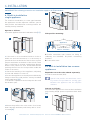
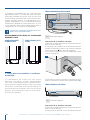
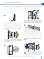
3.2 Electrical and Water connection
The Built-in filter cannot make it safe to
drink any water which is not suitable for
human consumption.
The appliance should be connected only
to a potable water supply system.
Do not use extension cords or adapters.
Once the appliance is fully installed, con-
nected to the water supply (if applicable)
and operational, in the event that the wa-
ter supply must be turned off, (touch the
button
on control panel to disable the
ice maker) before the main water is shut
off to prevent the appliance from entering
a ‘NO WATER IN’ alarm state.
The appliances are delivered from the factory for op-
eration at 110V-120V AC - 60Hz (US and Canada).
They are provided with a suitable supply cable and
plug to be connected to an appropriate 15A socket
providing an eective grounding.
A dedicated 15A circuit breaker should also be in-
stalled and should be easily accessible so that it can
be easily switched o before performing any installa-
tion or maintenance.
To connect to the water supply system (for appliances
equipped with ice makers) a 1/4” waterline with ac-
cessible shut-o valve must be supplied.
The appliance is provided with a water adapter elbow
which is suitable for the recommended water pres-
sure and complies the applicable food and water reg-
ulations..
The water filter cartridge, which is provided with the
appliance, should be installed according to the ac-
companying instructions. The solenoid connection on
the appliance is 3/4” diameter but is metric threaded
(NPT). A standard garden hose threaded connector
such as a braided stainless hose found at typical hard-
ware stores will strip or damage the solenoid threads.
It is recommended to use only the supplied 1/4” quick
connect elbow adapter for connecting a 1/4” copper
EN
1
4
1
2
3
EW
E W
EW
E W

14
www.fhiaba.com · www.thevettagroup.com · Info Line 1-855-4-FHIABA (1-855-434-4222)
or polyethylene source water line to the appliance.
Do not use extension cords and/or mul-
tiple adapters for the power supply con-
nection.
ELECTRICAL AND WATER SUPPLY
BEHIND THE UNIT
INTEGRATED AND
BRILLIANCE SERIES:
STANDPLUS AND
X-PRO SERIES:
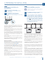
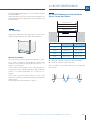
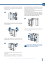
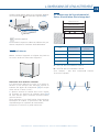
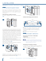
3.3 Energy: Alternatives and Home Auto-
mation
If energy is supplied through an alternative en-
ergy power source (solar, geothermal, etc..) or
if home automation systems are installed with
carrier signals in the power lines, it may be nec-
essary to install an isolation transformer (not
supplied) to prevent interference with the appli-
ance’s electronics.
INTEGRATED AND BRILLIANCE SERIES:
fig.1 Back of appliance
Operate as follows:
> Unwind the electric cable and connect it directly to
the wall socket.
> Make sure the appliance is in the Stand-by con-
dition and that all lights are o; should it be not so
press the Unit button
to switch it o.
X-PRO AND STANDPLUS SERIES:
Operate as follows:
> Unwind the electric cable and connect it directly to
the wall socket.
> Make sure the appliance is in the Stand-by con-
dition and that all ights are o; should it be not so
press the Unit button
to switch it o.
fig.2 Back of appliance
fig.3 Front of appliance
Water connection
Electrical connection
Electrical connection
Water connection
E
W
E
W
1
1

15
www.fhiaba.com · www.thevettagroup.com · Info Line 1-855-4-FHIABA (1-855-434-4222)
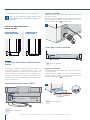
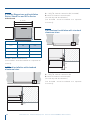
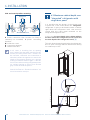
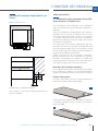
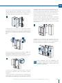
3.4 Levelling
Adjust the appliance level by means of the front
levelling feet and the rear adjustable wheels.
Operate as follows:
> If necessary, remove the bottom plinth or grille
(it is kept in position by magnets), adjust the
height of the levelling feet [ 1 ] by means of a 17
mm (11/16”) wrench.
> Then adjust the height of the rear wheels by
turning the front adjusting bolts [ 2 ] clockwise
(raise) or counter-clockwise as it may be re-
quired.
Take care if using a power driver for this and
lower the clutch to prevent damaging the leveling
mechanism.
> Remount the bottom plinth or grille.
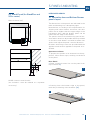
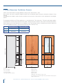
4.1 Niche Dimensions and Installation
Styles: Integrated Series
A - KCLITU: Lateral connection Kit (included)
B - KCCITU: Central connection Kit
(not included - must be ordered as a separate
accessory)
FI36
FI30
FI24
FI18
897 (35 1/4”)902 (35 1/2”)
752 (29 5/8”)
602 (23 3/4”)
452 (17 3/4”)
747 (29 3/8”)
447 (17 5/8”)
597 (23 1/2”)
Panels WidthNiche
Series
> Firmly tighten with fingers - a tool / wrench should
not be needed to
make a proper seal. Turn on the water and ensure all
connections are not leaking prior to pushing the unit
into the niche.
4. NICHE DIMENSIONS
EN
1
2
1
2
FI24: 602 (23 ¾”)
FI30: 752 (29 ⅝”)
FI36: 902 (35 ½”)
FI18: 452 (17 ¾”)
CCB

16
www.fhiaba.com · www.thevettagroup.com · Info Line 1-855-4-FHIABA (1-855-434-4222)
4.2 Niche Dimensions and Installation
Styles: StandPlus and X-Pro Series
Stand-Proud
KCLXB: Lateral connection Kit
(not included - must be ordered as a separate ac-
cessory)
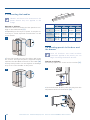
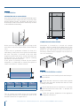
4.3 Flush installation with standard
aluminum trims
4.4 Prominent installation with standard
aluminum trims
A - KCLITU: Lateral connection Kit
B - KCCITU: Central connection Kit
(for side-by-side installations)
(not included - must be ordered as a separate
accessory)
A
6,5 (¼”)
A
6,5 (¼”)
10 (3⁄8”)
A - KCLITU: Lateral connection Kit (included)
B - KCCITU: Central connection Kit
(for side-by-side installations)
(not included - must be ordered as a separate
accessory)
902 (35 1/2”)
752 (29 5/8”)
602 (23 3/4”)
914 (36”
)
762
(30”)
610 (24”)
36
30
24
MAXMIN
Series
NICHE
24: 610 (24”)
30: 762 (30”)
36: 914 (36”)

17
www.fhiaba.com · www.thevettagroup.com · Info Line 1-855-4-FHIABA (1-855-434-4222)
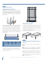
INTEGRATED SERIES
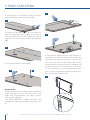
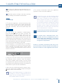
5.1 Decorative door and Bottom-Drawer
panels layout
The dimensions of the panels are indicated in the
table and drawings on subsequent pages.
Nevertheless, according to the requirements for
aligning with other kitchen structures, the door
panel can be higher than the upper edge of the
refrigerator door, and the drawer panel can be
lower than the edge of the drawer.
The panels must be mounted using special bra-
ckets which attach to adjustable devices provided
on the door and drawer and with brackets that
anchor and adjust the panel’s vertical direction.
Brackets and fixing screws are provided with the
appliance and must be applied to the panel as in-
dicated.
Operate as follows:
To prepare the panels to be mounted on the ap-
pliance, follow these steps, working on the back
of the panel.
Door Panel
> Draw a vertical center line on the panel from
top to bottom
1 ].
> Starting from the bottom edge of the panel,
mark the positioning of the brackets [ 2 ].
5. PANELS MOUNTING
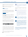
4.5 Stand-Proud (for StandPlus and
X-Pro series)
Niche 610 mm (24”)
KCLXB: Lateral connection Kit
(not included - must be ordered as a separate
accessory)
25 (1”)
20 (
¾”
)
15 (
5⁄8”
)
10 (
3⁄8”
)
610 (24”)
2
1
EN

18
www.fhiaba.com · www.thevettagroup.com · Info Line 1-855-4-FHIABA (1-855-434-4222)
> Following the corresponding table, mark the
external and then the internal hole [ 3 ].
> Position the brackets on each set of marks to
make sure they are aligned [ 4 ], if you choose to
drill small pilot holes for the screws pay special
attention to not pass through the panel entirely.
[ 5 ].
> Screw the brackets in place [ 6 ].
Drawer Panel
> When preparing the Drawer Panel, follow the
same instructions as per the door panel, but
make sure measurements are taken starting
from the top edge
[ 7 ].
The height-adjustment support brackets are
oriented the opposite way
[ 8 ] (note imgs 4 and
8).
8
7
65
4
3
9
> Prepare the appliance door (and drawer(s) if
applicable) for panel mounting by threading the
shoulder bolts into the recessed receivers and
the set screws into the other hole
[ 9 ]. Ensure
the end with the hex key socket is threaded into
the door and not on the visible end. Thread this
in far enough that it is flush with appliance door
face so as not to interferece with hanging the pa-
nel. You will adjust these later.
5. PANELS MOUNTING

19
www.fhiaba.com · www.thevettagroup.com · Info Line 1-855-4-FHIABA (1-855-434-4222)
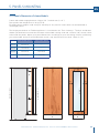
5.2 Decorative panels layout for Fridge
with one bottom-drawer
Holes positions:
SERIES 899 / 36” SERIES 749 / 30” SERIES 599 / 24”
A 897 (35 1/4”) 747 (29 3/8”) 597 (23 1/2”)
B 417 (16 3/8”) 342 (13 1/2”) 276.5 (10 7/8”)
C 354.5 (14”) 279.5 (11”) 203.5 (8”)
EN
A
BB
A
BB
C C
13 (½”)
34 (1
3⁄8”)
6,5 (
¼”) 6,5 (¼”)
34 (1
3⁄8”)
1273 (50 1⁄8”)
1163 (45
¾”)
660 (26”)
157 (6
¼”)
min 1390 (54
¾”)max 635 (25”)
507.5 (20”)
382 (15
1⁄8”)
100 (4”)

20
www.fhiaba.com · www.thevettagroup.com · Info Line 1-855-4-FHIABA (1-855-434-4222)
SERIES 899 / 36” SERIES 749 / 30”
A 897 (35 1/4”) 747 (29 3/8”)
B 417 (16 3/8”) 342 (13 1/2”)
C 354.5 (14”) 279.5 (11”)
5.3 Decorative panels layout
for Fridge with two bottom-drawers
Holes positions:
5. PANELS MOUNTING
A
min 1265 (49 ¾”)
1160 (45
5⁄8”)
1044 (41
1⁄8”)
600 (23
5⁄8”)
268 (10
½”)
292,5 (11
½”)
183 (7
¼”)
73 (2
7⁄8”)
66 (2
5⁄8”) 157 (6 ¼”)
337 (13
¼”)max 415 (16 3⁄8”)
13 (½”)
34 (1
3⁄8”)
6,5 (¼”) 6,5 (¼”)
BB
C C
BB
La page est en cours de chargement...
La page est en cours de chargement...
La page est en cours de chargement...
La page est en cours de chargement...
La page est en cours de chargement...
La page est en cours de chargement...
La page est en cours de chargement...
La page est en cours de chargement...
La page est en cours de chargement...
La page est en cours de chargement...
La page est en cours de chargement...
La page est en cours de chargement...
La page est en cours de chargement...
La page est en cours de chargement...
La page est en cours de chargement...
La page est en cours de chargement...
La page est en cours de chargement...
La page est en cours de chargement...
La page est en cours de chargement...
La page est en cours de chargement...
La page est en cours de chargement...
La page est en cours de chargement...
La page est en cours de chargement...
La page est en cours de chargement...
La page est en cours de chargement...
La page est en cours de chargement...
La page est en cours de chargement...
La page est en cours de chargement...
La page est en cours de chargement...
La page est en cours de chargement...
La page est en cours de chargement...
La page est en cours de chargement...
La page est en cours de chargement...
La page est en cours de chargement...
La page est en cours de chargement...
La page est en cours de chargement...
La page est en cours de chargement...
La page est en cours de chargement...
La page est en cours de chargement...
La page est en cours de chargement...
La page est en cours de chargement...
La page est en cours de chargement...
La page est en cours de chargement...
La page est en cours de chargement...
La page est en cours de chargement...
La page est en cours de chargement...
La page est en cours de chargement...
La page est en cours de chargement...
La page est en cours de chargement...
La page est en cours de chargement...
-
 1
1
-
 2
2
-
 3
3
-
 4
4
-
 5
5
-
 6
6
-
 7
7
-
 8
8
-
 9
9
-
 10
10
-
 11
11
-
 12
12
-
 13
13
-
 14
14
-
 15
15
-
 16
16
-
 17
17
-
 18
18
-
 19
19
-
 20
20
-
 21
21
-
 22
22
-
 23
23
-
 24
24
-
 25
25
-
 26
26
-
 27
27
-
 28
28
-
 29
29
-
 30
30
-
 31
31
-
 32
32
-
 33
33
-
 34
34
-
 35
35
-
 36
36
-
 37
37
-
 38
38
-
 39
39
-
 40
40
-
 41
41
-
 42
42
-
 43
43
-
 44
44
-
 45
45
-
 46
46
-
 47
47
-
 48
48
-
 49
49
-
 50
50
-
 51
51
-
 52
52
-
 53
53
-
 54
54
-
 55
55
-
 56
56
-
 57
57
-
 58
58
-
 59
59
-
 60
60
-
 61
61
-
 62
62
-
 63
63
-
 64
64
-
 65
65
-
 66
66
-
 67
67
-
 68
68
-
 69
69
-
 70
70


Fhiaba BKI30B-LS Guide d'installation
- Taper
- Guide d'installation
- Ce manuel convient également à
dans d''autres langues
- English: Fhiaba BKI30B-LS Installation guide
Documents connexes
-
Fhiaba BKI36BIRS Guide d'installation
-
-
Fhiaba BI30BI-LO Manuel utilisateur
-
-
-
Fhiaba FM24BWRLGS Guide d'installation
-
-
-
Fhiaba BKI36BI-LS Guide d'installation
Autres documents
-
Bertazzoni REF36PIXL Le manuel du propriétaire
-
Bertazzoni REF30BMBIXLT 15.5 cu. ft. Built-in Bottom Freezer Refrigerator Guide d'installation
-
Bertazzoni 30 Inch Built In Bottom Freezer Refrigerator Manuel utilisateur
-
Signature Kitchen Suite SKSCW241RP Guide d'installation
-
Rubi RNK24- Guide d'installation
-
Bertazzoni REF24FCIPIXR Guide d'installation
-
KitchenAid KRVB 6031 Guide d'installation
-
-
KitchenAid KCVCX 20900L Mode d'emploi
-
Camp Chef FP30 Manuel utilisateur