La page est en cours de chargement...

Installation
P.O. Box 309
Menomonee Falls, WI 53052 USA
800 BRADLEY (800 272 3539)
+1 262 251 6000
bradleycorp.com
HDWT-INSTR-009 Rev K; ECN 17-14-007
© 2018 Bradley
Page 1 of 83 3/21/2018
Powder Coated & Stainless Steel Restroom
Partitions
Floor-Mounted with Overhead Brace
Series 400
Cloisons de toilettes en acier inoxydable et
à peinture en poudre
à fixation au sol et barre de tête
Série 400
Divisiones para baños con revestimiento
de polvo y de acero inoxidable para
montaje en el piso con soporte superior
Serie 400
*HDWT-INSTR-009*
For Standard Height
Doors and Panels Only
Pour portes et panneau de
hauteur standard seulement
Solo para puertas y paneles
de altura estándar

2
Powder Coated & Stainless Steel Restroom Partitions, Floor-Mounted with Overhead Brace — Series 400 Installation
3/21/2018 Bradley • HDWT-INSTR-009 Rev K; ECN 17-14-007
Table of Contents
Pre-Installation Information .................................................................................3
Supplies Required ........................................................................................4
Hardware Provided........................................................................................4
Example of Submittal Drawing ...............................................................................4
Layout Dimensions for Brackets..............................................................................5
Mounting Brackets to Wall ................................................................................6-7
Leveling Bolts to Pilaster ...................................................................................7
Pilaster Mounting Hardware...............................................................................8-9
Pilasters and Panels...................................................................................10-12
Telescoping and Wall Hung Pilasters ......................................................................13-16
Headrail ...............................................................................................17
Pilaster Shoes ..........................................................................................18
Hinges .............................................................................................19-22
Door Hardware.......................................................................................23-26
Urinal Screens .......................................................................................27-29
Table des matières
Avant l’installation........................................................................................30
Fournitures requises......................................................................................31
Visserie fournie..........................................................................................31
Exemple de plan de soumission .........................................................................31-32
Dimensions de placement - Supports continus (en option) ........................................................32
Montage des supports au mur ...........................................................................33-34
Vis de niveau sur montant .................................................................................34
Montage des supports sur les montants ...................................................................35-36
Visserie de fixation de montant .............................................................................36
Montants et panneaux .................................................................................37-39
Montants télescopiques et fixés au mur....................................................................40-43
Barre de tête............................................................................................44
Sabots de montant .......................................................................................45
Charnières ..........................................................................................46-49
Quincaillerie de porte ..................................................................................50-53
Séparateurs d’urinoir ..................................................................................54-56
Contenido
Información previa a la instalación...........................................................................57
Materiales necesarios ....................................................................................58
Piezas metálicas proporcionadas............................................................................58
Ejemplo de plano original..................................................................................58
Dimensiones de diseño para los soportes.....................................................................59
Soporte de montaje para pared ..........................................................................60-61
Pernos niveladores para pilastra ............................................................................61
Soporte de montaje para pilastras........................................................................62-63
Pilastras y paneles ....................................................................................64-66
Pilastras de extensión y para montaje en la pared ...........................................................67-70
Dintel .................................................................................................71
Pedestales para pilastra...................................................................................72
Bisagras ............................................................................................73-76
Piezas metálicas para puertas...........................................................................77-80
Mamparas del urinario .................................................................................81-83

3
Installation Powder Coated & Stainless Steel Restroom Partitions, Floor-Mounted with Overhead Brace — Series 400
Bradley • HDWT-INSTR-009 Rev K; ECN 17-14-007 3/21/2018
WARNING
Before beginning installation, make sure that the wall and floor backing are adequate to support the secure
mounting of the toilet compartment units.
NOTICE
To prevent warping, always lay the material flat. Do not lean the material against the wall or stack unevenly.
To prevent "dimpling," extra caution should be taken when instructed to drill through one side of face only.
IMPORTANT
Read this installation manual completely to ensure proper installation, then file it with the owner or
maintenance department. This installation manual provides instruction for the assembly of normal partition
configurations and standard components. Non-standard configurations or components including but not
limited to curved or angled walls, partial walls, oversized panels, or modified hardware are not covered in
this manual. Compliance and conformity to local codes and ordinances is the responsibility of the installer.
Separate parts from packaging and make sure all parts are accounted for before discarding packaging
material. If any parts are missing, do not begin installation until you obtain the missing parts.
Product warranties and parts information may be found on Bradley's web site at bradleycorp.com.

4
Powder Coated & Stainless Steel Restroom Partitions, Floor-Mounted with Overhead Brace — Series 400 Installation
3/21/2018 Bradley • HDWT-INSTR-009 Rev K; ECN 17-14-007
HR062
HR120
Supplies Required:
Hardware Provided
#14-16 Plastic
Anchor
FAST-T373
#14 x 2"
Button-Head
Sheet Metal Screw
Torx-T27 Drive
FAST-P002
(Stainless)
#10 x 5/8"
Button-Head
Sheet Metal Screw
Torx-T27 Drive
FAST-Z0019
Example of Submittal Drawing
• Chalk line and pencil
• Tape measure and 4' level
• Jigsaw (or hacksaw) and circular saw
• Two spring clamps
• 1/8", 9/64", 3/16", 7/32" and 1/4" drill bits
• Power drill or screw gun with drill bit extension
• 1/4" and 5/16" ceramic tile and masonry drill bit
• Hammer drill
• Spacer, 12" (305mm) high and strong enough to
support weight of panel
#14 x 5/8"
Button-Head
Sheet Metal Screw
Torx-T27 Drive
FAST-Z0016
#5-40 x 11/16"
Flat-Head
Sheet Metal Screw
Torx-T10 Drive
FAST-T300
1/4" - 14 x 5/8"
Sheet Metal Screw
Torx-T27 Drive
FAST-S355A
#10 x 3/4"
Flat-Head
Sheet Metal Screw
Torx-T25 Drive
FAST-Z0006
#14 x 2"
Button-Head
Sheet Metal Screw
Torx-T27 Drive
FAST-Z002
(Chrome Plated)
#10-24 x 3/4"
Button-Head
Barrel Nut
Torx-T27 Drive
FAST-Z003
(Chrome Plated)
#10-24 x 3/4"
Button-Head
Barrel Nut
Torx-T27 Drive
FAST-P003
(Stainless)
#10-24 x 3/4"
Button-Head
Shoulder Screw
Torx-T27 Drive
FAST-Z004
(Chrome Plated)
#10-24 x 3/4"
Button-Head
Shoulder Screw
Torx-T27 Drive
FAST-P004
(Stainless)
#10-24 x 1"
Button-Head
Shoulder Screw
Torx-T27 Drive
FAST-Z004A
(Chrome Plated)
#10-24 x 1"
Button-Head
Shoulder Screw
Torx-T27 Drive
FAST-P004A
(Stainless)
#10 x 2"
Flat-Head
Machine Screw
Torx-T25 Drive
FAST-Z0027
5/16" - 18 x 3"
Leveling Bolt
FAST-S0039
61-1/4"
(1556mm)
to face
60-1/2"
(1537mm)
wall to
centerline
36"
(914mm)
center to
center
36"
(914mm)
24"
(610mm)
26"
(660mm)
8"
(203mm)
3" (76mm)
1" (25mm) gap
1"
(25mm)
gap
1/2"
(13mm)
gap
3"
3-1/2"
1-1/2"
20-1/2"
6-1/2"
58-1/2"
(1486mm)
58-1/2"
(1486mm)
#10 x 2"
Flat-Head
Sheet Metal Screw
Torx-T25 Drive
Fast-S0023
#10 x 5/8"
Button-Head
Sheet Metal Screw
Torx-T27 Drive
FAST-S351A

5
Installation Powder Coated & Stainless Steel Restroom Partitions, Floor-Mounted with Overhead Brace — Series 400
Bradley • HDWT-INSTR-009 Rev K; ECN 17-14-007 3/21/2018
*
*
*
*
*
*
C
L
C
L
C
L
C
L
C
L
C
L
Pilaster plumb line
When installing the partition components, consult
the applicable Mills Partition submittal drawing
for compartment layout dimensions.
1
Layout Dimensions - Stirrup Brackets (Standard)
Pilaster centerline: Measure from
the back wall forward to the face of the
compartment, subtract 5/8" (16mm) and
mark this location on the floor (“A”). Mark
the same measurement on the opposite end
of your layout (“A1”) and draw a straight line
connecting both marks.
For freestanding (FS) partitions: Refer
to submittal drawings and determine the
approximate location of the outside panels.
Establish dimensions “A” and “A1” as
explained above.
A
Panel centerline: Measure the stall width across the
back wall and place a mark at the base of the rear wall
(“B”). Repeat this step for each panel, starting each
measurement from the last panel centerline (“B1”).
B
Draw a plumb line on all walls from each pilaster
and panel centerline. From the highest point in the
room, measure 18" (457mm) and 64" (1626mm)
from the floor and place a mark on the pilaster/
panel plumb line. These marks represent the hole
center line of the stirrup brackets. Use a level to
transfer that mark to all other plumb lines (“C”).
C
Panel
plumb line
C
L
C
L
C
L
C
L
*
*
*
Pilaster plumb line
When installing the partition components,
consult the applicable Mills Partition submittal
drawing for compartment layout dimensions.
1a
Layout Dimensions - Continuous Brackets (Optional)
Pilaster centerline: Measure from
the back wall forward to the face of the
compartment, subtract 5/8" (16mm)
and mark this location on the floor (“A”).
Mark the same measurement on the
opposite end of your layout (“A1”) and
draw a straight line connecting both
marks.
For freestanding (FS) partitions:
Refer to submittal drawings and
determine the approximate location
of the outside panels. Establish
dimensions “A” and “A1” as explained
above.
A
Panel centerline: Measure the stall width across the
back wall and place a mark at the base of the rear wall
(“B”). Repeat this step for each panel, starting each
measurement from the last panel centerline (“B1”).
B
Draw a plumb line on all walls from each pilaster and panel
centerline. From the highest point in the room, measure from
the floor and place a mark on the pilaster/panel plumb line at
dimension "C" for the respective bracket type (see table below).
Use a level to transfer that mark to all other plumb lines "D".
C
Panel
plumb line
64"
(1626mm)
18"
(457mm)
"C"
"D"
"C"
"D"
"C"
"D"
"C"
"C"
"B"
"B"
"B1"
"B1"
"A1"
"A1"
"A"
"A"
"C"
"C"
Dim "C"
Stainless
Steel
12-1/2"
(318mm)
Aluminum
12-1/4"
(311mm)

6
Powder Coated & Stainless Steel Restroom Partitions, Floor-Mounted with Overhead Brace — Series 400 Installation
3/21/2018 Bradley • HDWT-INSTR-009 Rev K; ECN 17-14-007
2
Stirrup Brackets to Wall (Standard)
established level line
pilaster/panel plumb line
floor
C
L
Place the center of each stirrup bracket
at the established level line. Center the
bracket opening on the pilaster/panel
plumb line.
A
Insert the plastic anchors in all holes and
secure the brackets to the wall with the
#14 x 2" screws provided.
C
On end panel and pilaster applications, position the bracket
with the ear facing toward the inside of the stall.
Using the bracket as a template, mark the
hole locations on the wall. Remove the
bracket and drill a Ø5/16" hole (min. 2"
[51mm] deep) at each hole location.
B
One-Eared
Bracket
Two-Eared
Bracket
Pilaster bracket is shown here; 1-1/4" opening brackets are
for pilasters, and 1" opening brackets are for panels.
2a
Continuous Stainless Steel Brackets to Wall (Optional)
established level line
pilaster plumb
line
floor
C
L
Place the bottom of each continuous
bracket at the established level line.
Center the bracket opening on the
pilaster/panel plumb line.
A
Insert the plastic anchors in all holes and
secure the brackets to the wall with the
#14 x 2" stainless screws provided.
C
On pilaster applications, position the bracket with the ear
facing toward the inside of the stall.
Using the bracket as a template, mark the
hole locations on the wall. Remove the
bracket and drill a Ø5/16" hole (min. 2"
[51mm] deep) at each hole location.
B
Brackets are used as templates, but since the hole patterns
may be different, the brackets may not be interchangeable.
Pilaster bracket is shown here; "Ear" brackets are for pilasters, and
"U" brackets are for panels.
"Ear"
Bracket
"U" Bracket

7
Installation Powder Coated & Stainless Steel Restroom Partitions, Floor-Mounted with Overhead Brace — Series 400
Bradley • HDWT-INSTR-009 Rev K; ECN 17-14-007 3/21/2018
2b
Continuous Aluminum Brackets to Wall (Optional)
established level line
pilaster/panel
plumb line
floor
C
L
Place the bottom of each continuous
bracket at the established level line.
Center the bracket opening on the
pilaster/panel plumb line.
A
Insert the plastic anchors in all holes and
secure the brackets to the wall with the
#14 x 2" stainless screws provided.
C
On end panel and pilaster applications, position the bracket
with the ear facing toward the inside of the stall.
Using the bracket as a template, mark the
hole locations on the wall. Remove the
bracket and drill a Ø5/16" hole (min. 2"
[51mm] deep) at each hole location.
B
Brackets are used as templates, but since the hole patterns
may be different, the brackets may not be interchangeable.
Pilaster bracket is shown here; 1-1/4" opening brackets are for
pilasters, and 1" opening brackets are for panels.
One-Eared
Bracket
Two-Eared
Bracket
3
Leveling Bolts to Pilaster
Use leveling bolt(s) to adjust height of pilaster
as indicated based on pilaster width.
A
3" Pilaster 4" - 14" Pilaster 18" - 24" Pilaster
4" - 8" pilasters have a single, 1-piece bracket that uses a
leveling bolt in the center to adjust the pilaster height.

8
Powder Coated & Stainless Steel Restroom Partitions, Floor-Mounted with Overhead Brace — Series 400 Installation
3/21/2018 Bradley • HDWT-INSTR-009 Rev K; ECN 17-14-007
4
Stirrup Brackets to Pilaster (Standard)
Refer to the submittal drawing to locate the split
dimension and layout location of each marked pilaster.
Measure 17-7/16 (443mm) and 63-7/16" (1611mm) down from
the top of each pilaster and place a mark on the pilaster split
centerline.
A
Split
Split
17-7/16"
(443mm)
63-7/16"
(1611mm)
Place stirrup brackets at each established level line. Center
the bracket opening on the pilaster split centerline. Using the
bracket as a template, mark the hole locations on the pilaster.
Remove the bracket and drill a Ø3/16" pilot hole (through
inside face of pilaster only) at each location.
B
Secure the stirrup brackets to the pilasters using the #14 x 5/8"
screws provided.
C
4a
Continuous Brackets to Pilaster (Optional)
Refer to the submittal drawing to locate the split
dimension and layout location of each marked pilaster.
Measure down from the top of the pilaster and
place a mark on the pilaster split centerline
at dimensions "A" and "B" for the respective
bracket (see table at left).
A
Secure the continuous bracket to the
pilasters using the #14 x 5/8" stainless
screws provided.
C
Split
Split
"A"
"B"
Dim. "A" Dim. "B"
Stainless
Steel
Bracket
11-15/16"
(302mm)
69-15/16"
(1749mm)
Aluminum
Bracket
11-11/16"
(297mm)
69-3/16"
(1749mm)
Place the continuous bracket between each
established level line. Center the bracket
opening on the pilaster split centerline. Using
the bracket as a template, mark the hole
locations on the pilaster. Remove the bracket
and drill a Ø3/16" pilot hole (through inside
face of pilaster only) at each location.
B
Brackets are used as templates but since the hole patterns
may be different, the brackets may not be interchangeable.
Continuous stainless steel bracket shown.
Pilaster shown is for reference only. Actual pilaster varies
depending on application.
Pilaster shown is for reference only. Actual
pilaster varies depending on application.
C
L
C
L
C
L

9
Installation Powder Coated & Stainless Steel Restroom Partitions, Floor-Mounted with Overhead Brace — Series 400
Bradley • HDWT-INSTR-009 Rev K; ECN 17-14-007 3/21/2018
5
Pilaster Mounting Hardware
This view is an example only. Refer to your submittal drawings to determine placement of the anchors on the pilaster
centerline for your application. Typical anchor centers are measured 1" (25mm) in from each edge of the pilaster (except 3"
pilasters where only one anchor is used).
A
Insert plastic anchors into the holes and
fasten the "L" brackets to the anchors
using the #14 x 2" screws provided.
C
Drill Ø5/16" holes (min 2" [51mm] deep) in
the floor and make sure the holes are free
of dirt and debris.
B
38"
(965mm)
Pilaster Centerline
22"
(559mm)
3"
(76mm)
6"
(152mm)
28"
(711mm)
4b
Alcove Brackets to Pilaster
Layouts that use continuous aluminum brackets for pilaster and panel connections will use stirrup brackets for alcove connections.
Continuous stainless steel brackets use continuous alcove brackets.
Refer to the submittal drawing for the layout location of each alcove pilaster.
Measure down from the top of
the pilaster and place a mark at
dimensions shown for the respective
bracket situation.
A
Stirrup: Position the center of each
bracket at the marks made in Step A.
Continuous: Center the bracket
between each mark made in Step A.
B
Using the bracket as a template,
mark the hole locations on the
pilaster. Remove the bracket and drill
Ø3/16" holes through the pilaster at
each location.
C
Secure the bracket(s) to the
pilaster using the #14 x 5/8" screws
(stainless on continuous) provided.
D
63-7/16"
(1611mm)
17-7/16"
(443mm)
Stirrup
Continuous
68-15/16"
(1749mm)
11-15/16"
(302mm)

10
Powder Coated & Stainless Steel Restroom Partitions, Floor-Mounted with Overhead Brace — Series 400 Installation
3/21/2018 Bradley • HDWT-INSTR-009 Rev K; ECN 17-14-007
6
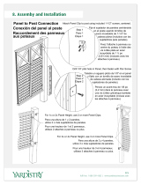
Pilasters and Panels with Stirrup Brackets (Standard)
Pilasters located at walls should be mounted first. Start at one end and install a panel, then a pilaster. Continue alternating until
installation is complete. When installing in an alcove or in-corner, use an alcove bracket to secure the pilaster to the panel.
Pilasters at Wall
Pilasters with Panels
Check to make sure the pilasters are plumb and level to each other. The pilaster height can be adjusted with the leveling bolt that
was placed at the bottom of the pilaster (see page 5 for attaching leveling bolt).
When installing pilasters at walls, the gaps range
from 1/2" to 1-1/4" (13mm to 32mm). Refer to your
submittal drawing for your gap sizes.
Refer to your submittal drawing and leave the appropriate
gaps. Standard gap is 1" (25mm) between the panel and
wall and 1/2" (13mm) between the panel and pilaster.
Spacer 12" (305mm)
Slide the shoe onto the bottom of the pilaster and
use a piece of tape to keep the shoe positioned
above the mounting hardware. Make sure the shoe
mounting hole is facing inside the stall and that the
hole is towards the top.
A
Position the pilaster so the mounting bracket(s)
sits on the inside of the floor "L" bracket(s) while at
the same time placing the pilaster within the wall
brackets. Secure the pilaster mounting bracket(s) to
the floor "L" bracket(s) using the #14 x 5/8" screw(s)
provided.
B
Using the bracket as a template, drill Ø3/16" holes
through the pilaster at each pilaster bracket hole.
Secure the pilaster to the bracket using the
#14 x 5/8" screws provided.
C
Using the bracket as a template, drill Ø3/16" holes through
the panel at each panel bracket hole. Secure the panel to
the bracket using the #14 x 5/8" screws provided.
D
Place the panel on the spacer and insert the panel into the
wall brackets.
A
Slide the shoe onto the bottom of the pilaster and use
a piece of tape to keep the shoe positioned above the
mounting hardware. Make sure the shoe mounting hole is
facing inside the stall and that the hole is towards the top.
B
Position the pilaster so the mounting bracket(s)sits on the
inside of the floor "L" bracket(s) while at the same time
placing the brackets around the panel. Secure the pilaster
mounting bracket(s) to the floor "L" bracket(s) using the
#14 x 5/8" screw(s) provided.
C

11
Installation Powder Coated & Stainless Steel Restroom Partitions, Floor-Mounted with Overhead Brace — Series 400
Bradley • HDWT-INSTR-009 Rev K; ECN 17-14-007 3/21/2018
Pilasters at Wall Pilasters with Panels
6a
Pilasters and Panels with Stainless Steel Continuous Brackets (Optional)
Pilasters located at walls should be mounted first. Start at one end and install a panel, then a pilaster. Continue alternating until
installation is complete. When installing in an alcove or in-corner, use an alcove bracket to secure the pilaster to the panel.
Check to make sure the pilasters are plumb and level to each other. The pilaster height can be adjusted with the
leveling bolt that was placed at the bottom of the pilaster (see page 5 for attaching leveling bolt).
Spacer 12" (305mm)
When installing pilasters at walls, the gaps range
from 1/2" to 1-1/4" (13mm to 32mm). Refer to your
submittal drawing for your gap sizes.
Refer to your submittal drawing and leave the appropriate
gaps. Standard gap is 1" (25mm) between the panel and
wall and 1/2" (13mm) between the panel and pilaster.
Slide the shoe onto the bottom of the pilaster and
use a piece of tape to keep the shoe positioned
above the mounting hardware. Make sure the shoe
mounting hole is facing inside the stall and that the
hole is towards the top.
A
Position the pilaster so the mounting bracket(s)
sits on the inside of the floor "L" bracket(s) while at
the same time placing the pilaster within the wall
bracket. Secure the pilaster mounting bracket(s) to
the floor "L" bracket(s) using the #14 x 5/8" screw(s)
provided.
B
Place the panel on the spacer and insert the panel into the
wall bracket.
A
Slide the shoe onto the bottom of the pilaster and use a piece
of tape to keep the shoe positioned above the mounting
hardware. Make sure the shoe mounting hole is facing inside
the stall and that the hole is towards the top.
B
Position the pilaster so the mounting bracket(s) sits on the
inside of the floor "L" bracket(s) while at the same time placing
the bracket around the panel. Secure the pilaster mounting
bracket(s) to the floor "L" bracket(s) using the #14 x 5/8"
screw(s) provided.
C
Using the bracket as a template, drill Ø3/16" holes
through the pilaster at each pilaster bracket hole.
Secure the pilaster to the bracket using the
#14 x 5/8" stainless screws provided.
C
Using the bracket as a template, drill Ø3/16" holes through
the panel at each panel bracket hole. Secure the panel to the
bracket using the #14 x 5/8" stainless screws provided.
D

12
Powder Coated & Stainless Steel Restroom Partitions, Floor-Mounted with Overhead Brace — Series 400 Installation
3/21/2018 Bradley • HDWT-INSTR-009 Rev K; ECN 17-14-007
Pilasters at Wall Pilasters with Panels
6b
Pilasters and Panels with Aluminum Continuous Brackets (Optional)
Pilasters located at walls should be mounted first. Start at one end and install a panel, then a pilaster. Continue alternating until
installation is complete. When installing in an alcove or in-corner, use an alcove bracket to secure the pilaster to the panel.
Check to make sure the pilasters are plumb and level to each other. The pilaster height can be adjusted with the
leveling bolt that was placed at the bottom of the pilaster (see page 5 for attaching leveling bolt).
Spacer 12" (305mm)
When installing pilasters at walls, the gaps range
from 1/2" to 1-1/4" (13mm to 32mm). Refer to your
submittal drawing for your gap sizes.
Refer to your submittal drawing and leave the appropriate
gaps. Standard gap is 1" (25mm) between the panel and
wall and 1/2" (13mm) between the panel and pilaster.
Slide the shoe onto the bottom of the pilaster and
use a piece of tape to keep the shoe positioned
above the mounting hardware. Make sure the shoe
mounting hole is facing inside the stall and that the
hole is towards the top.
A
Position the pilaster so the mounting bracket(s)
sits on the inside of the floor "L" bracket(s) while at
the same time placing the pilaster within the wall
bracket. Secure the pilaster mounting bracket(s) to
the floor "L" bracket(s) using the #14 x 5/8" screw(s)
provided.
B
Using the bracket as a template, drill Ø1/4" holes
through the pilaster at each pilaster bracket hole.
Secure the pilaster to the bracket using the
#10-24 x 3/4" stainless barrel nuts and #10-24 x 1"
stainless shoulder screws provided.
C
Using the bracket as a template, drill Ø1/4" holes through the
panel at each panel bracket hole. Secure the panel to the
bracket using the #10-24 x 3/4" stainless barrel nuts and
#10-24 x 3/4" stainless shoulder screws provided.
D
Place the panel on the spacer and insert the panel into the
wall bracket.
A
Slide the shoe onto the bottom of the pilaster and use a piece
of tape to keep the shoe positioned above the mounting
hardware. Make sure the shoe mounting hole is facing inside
the stall and that the hole is towards the top.
B
Position the pilaster so the mounting bracket(s) sits on the
inside of the floor "L" bracket(s) while at the same time placing
the bracket around the panel. Secure the pilaster mounting
bracket(s) to the floor "L" bracket(s) using the #14 x 5/8"
screw(s) provided.
C

13
Installation Powder Coated & Stainless Steel Restroom Partitions, Floor-Mounted with Overhead Brace — Series 400
Bradley • HDWT-INSTR-009 Rev K; ECN 17-14-007 3/21/2018
6c
Telescoping Pilasters (Optional)
Mounting channels are used as templates but may not be interchanged because the hole patterns may be different.
Floor
Pilaster Plumb Line
Mounting Channel
12-1/8" (308mm)
to Bottom of
Channel (Highest
Point in Floor)
Telescoping Pilaster at Wall
Wall, Pilaster or Panel
Mounting Channel
Telescoping
Channel
Specified
Dimension
Telescoping Pilaster at Pilaster
12-5/16"
(313mm)
Pilaster
Centerline
Mounting Channel
Wall: From the highest point in the room, measure 12-1/8"
(308mm) up from the floor and transfer this level line to
the pilaster plumb line. Place the bottom of the mounting
channel at the level line and center the channel opening on
the plumb line.
Pilaster: Measure 12-5/16" (313mm) down from the top
of the pilaster and place a mark on the pilaster centerline.
Place the top of the mounting channel at this mark and
center the channel opening on the centerline.
A
Wall: Using the mounting channel as a template, mark the
hole locations and remove mounting channel. Drill a Ø5/16"
hole (min 2" [51mm] deep) at each hole location.
Pilaster: Using the mounting channel as a template, mark
the hole locations and remove the mounting channel. Drill a
Ø1/4" hole through the pilaster.
B
Wall: Insert the plastic anchors in all holes and secure
the mounting channel to the wall with the #14 x 2" screws
provided.
Pilaster: Secure the mounting channel to the pilaster with
the #10-24 x 3/4" barrel nuts and the #10-24 x 1" shoulder
screws provided.
C
Slide the telescoping channel over the mounting channel.
Refer to the submittal drawings and adjust the width to
meet the specified dimension.
D
Using the holes in the telescoping channel as a template,
drill Ø3/16" holes through the mounting channel. Secure the
telescoping channel to the mounting channel with the
#14 x 5/8" screws provided.
E

14
Powder Coated & Stainless Steel Restroom Partitions, Floor-Mounted with Overhead Brace — Series 400 Installation
3/21/2018 Bradley • HDWT-INSTR-009 Rev K; ECN 17-14-007
6d
Wall-Hung Pilasters (58" or 69-9/16") - Stirrup Brackets (Optional)
To establish level line, from the highest point in the room, measure 12" (305mm) from the floor. Use a level to transfer
this mark to the pilaster plumb line.
See Step 2 for instructions on mounting the stirrup brackets to a wall.
Wall
Specified Dimension
(Standard Gap 1")
12"
(305mm)
Pilaster
Plumb Line
Floor
Pilasters at Wall Pilasters at Pilasters
Specified
Dimension
See Step 4 for instructions on mounting the stirrup brackets to a pilaster.
Floor
Pilasters shown in two different lengths for visual reference.
69-9/16" (1767mm)
Pilaster
58" (1473mm)
Pilaster
Slide the wall-hung pilaster into the stirrup brackets
and align with the established level line. Refer to
the submittal drawing and adjust to meet the
specified dimension.
A
Using the stirrup brackets as a template, drill
Ø3/16" holes through the pilaster at each bracket
hole. Secure the pilaster to the bracket using the
#14 x 5/8" screws provided.
B
12"
(305mm)
C
L
69-9/16" (1767mm)
Pilaster
58" (1473mm)
Pilaster

15
Installation Powder Coated & Stainless Steel Restroom Partitions, Floor-Mounted with Overhead Brace — Series 400
Bradley • HDWT-INSTR-009 Rev K; ECN 17-14-007 3/21/2018
6e
Wall-Hung Pilasters (58" or 69-9/16") - Continuous Stainless Steel Brackets (Optional)
To establish level line, from the highest point in the room, measure 12" (305mm) from the floor. Use a level to transfer
this mark to the pilaster plumb line.
See Step 2a for instructions on mounting the continuous stainless
steel brackets to a wall.
Wall
Specified Dimension
(Standard Gap 1")
Pilaster
Plumb Line
Floor
Pilasters at Wall Pilasters at Pilasters
Specified
Dimension
See Step 4a for instructions on mounting the continuous stainless
steel brackets to a pilaster.
Floor
Pilasters shown in two different lengths for visual reference.
Slide the wall-hung pilaster into the continuous
bracket and align with the established level line.
Refer to the submittal drawing and adjust to meet
the specified dimension.
A
Using the continuous bracket as a template, drill
Ø3/16" holes through the pilaster at each bracket
hole. Secure the pilaster to the bracket using the
#14 x 5/8" stainless screws provided.
B
12"
(305mm)
12"
(305mm)
C
L
69-9/16" (1767mm)
Pilaster
58" (1473mm)
Pilaster
69-9/16" (1767mm)
Pilaster
58" (1473mm)
Pilaster

16
Powder Coated & Stainless Steel Restroom Partitions, Floor-Mounted with Overhead Brace — Series 400 Installation
3/21/2018 Bradley • HDWT-INSTR-009 Rev K; ECN 17-14-007
6f
Wall-Hung Pilasters (58" or 69-9/16") - Continuous Aluminum Brackets (Optional)
To establish level line, from the highest point in the room, measure 12" (305mm) from the floor. Use a level to transfer
this mark to the pilaster plumb line.
See Step 2b for instructions on mounting the continuous aluminum
brackets to a wall.
Wall
Specified Dimension
(Standard Gap 1")
Pilaster
Plumb Line
Floor
Pilasters at Wall Pilasters at Pilasters
Specified
Dimension
See Step 4a for instructions on mounting the continuous
aluminum brackets to a pilaster.
Floor
Pilasters shown in two different lengths for visual reference.
Slide the wall-hung pilaster into the continuous
bracket and align with the established level line.
Refer to the submittal drawing and adjust to meet
the specified dimension.
A
Using the continuous bracket as a template, drill
Ø1/4" holes through the pilaster at each bracket
hole. Secure the pilaster to the bracket using the
#10-24 x 3/4" stainless barrel nuts and #10-24 x 1"
stainless shoulder screws provided.
B
12"
(305mm)
12"
(305mm)
69-9/16" (1767mm)
Pilaster
58" (1473mm)
Pilaster
69-9/16" (1767mm)
Pilaster
58" (1473mm)
Pilaster
C
L

17
Installation Powder Coated & Stainless Steel Restroom Partitions, Floor-Mounted with Overhead Brace — Series 400
Bradley • HDWT-INSTR-009 Rev K; ECN 17-14-007 3/21/2018
7
Headrail
Make sure the pilasters are plumb and that the pilaster has been secured to the mounting hardware. Leave the appropriate
door opening between the pilasters as shown on your submittal drawing.
Completed Headrail Assembly
The illustrations on this page show mounting hardware and fasteners for a generic application. Refer to your submittals
to determine your actual headrail configurations.
Some headrail sections may need to be cut to an appropriate size. Refer to your submittals for general headrail placement.
Headrail configurations that come to an intersection should meet over pilaster (see completed headrail assembly view below).
Wall
Place headrail over the top of each pilaster
located at the wall and slide it tight against the
side wall. Mark the outline of the headrail on the
wall and remove the headrail.
A
Place the headrail bracket on
the outline marked on the wall
and mark the locations of the
mounting holes. Remove bracket
and drill (2) Ø5/16" holes a
minimum of 2" [51 mm] deep.
Prior to securing to the wall,
enlarge the (2) back mounting
holes of the bracket to Ø1/4".
Secure the bracket to the wall
with the #14 x 2" screws and
plastic anchors provided.
B
Place headrail over the top of the pilasters and
slide it tight into the mounting bracket. Use the
mounting bracket as a template and drill a Ø7/32"
hole through the headrail. Secure the headrail to
the mounting bracket with the #10 x 5/8" screws
provided.
C
Make sure the pilaster is plumb
and that the spacing between
the pilasters for the doors is the
correct dimension. On the back
of each pilaster (starting with the
first pilaster), drill a Ø7/32" hole
through one face of the headrail
only.
Using this hole as a template,
drill a Ø9/64" pilot hole into the
pilaster, 5/8" (16mm) deep.
Secure the headrail to the
back of each pilaster with the
#10 x 5/8" screws provided.
D
For open end applications, cut the headrail to the appropriate length (if
required). Attach the bracket to the wall at the correct height (see step B).
Attach another bracket to a pilaster with #10 x 5/8" screws at the correct height
(see view below). The headrail should be level with any adjacent headrail
and should be located directly over the panel. Position each headrail onto the
brackets and secure with required fasteners (see step C). Using a rubber mallet,
install the headrail end cap.
E

18
Powder Coated & Stainless Steel Restroom Partitions, Floor-Mounted with Overhead Brace — Series 400 Installation
3/21/2018 Bradley • HDWT-INSTR-009 Rev K; ECN 17-14-007
8
Pilaster Shoes
Position pilaster shoe so that it rests flush with the floor.
A
Using the hole(s) in the shoe as a template, drill a Ø9/64"
pilot hole (through inside face of pilaster only). Secure
the shoe to the pilaster using the #10 x 5/8" fastener(s)
provided.
B

19
Installation Powder Coated & Stainless Steel Restroom Partitions, Floor-Mounted with Overhead Brace — Series 400
Bradley • HDWT-INSTR-009 Rev K; ECN 17-14-007 3/21/2018
9
Wraparound Gravity Hinges (Standard)
Before installing the hinges, make sure the door openings are the appropriate size, all pilasters are plumb,
secured to the floor and that the headrail is installed.
Right-hand
inswing
(RHI)
Left-hand
inswing
(LHI)
Right-hand
outswing
(RHO)
Left-hand
outswing
(LHO)
"A"
"B" "B" "B"
"A"
"A"
Dim. "A" Dim. "B"
Floor
Mounted
Overhead
Braced
13-1/2"
(343mm)
67-5/8"
(1718mm)
Wall Hung
69-9/16"
(1767mm)
13-1/2"
(343mm)
67-5/8"
(1718mm)
Wall Hung
58"
(1473mm)
2-1/16"
(52mm)
56-3/16"
(1427mm)
Floor Mounted Overhead Braced
Wall Hung
69-9/16" (1767mm)
Wall Hung
58" (1473mm)
For 58" wall hung pilaster, establishing dimensions "A" and "B" as shown in the table will
result in the top of the door being flush with the top of the pilaster when the desired cam
setting on the door is set to 0°.
Refer to your submittal drawings to determine each specific door swing for your application. The door swing is
determined by facing the compartment from the outside. The image below can help determine the door swing type.
Measure down from the top of the pilaster and
place a mark at dimensions "A" and "B" for the
respective pilaster type (see table below). This
mark represents the upper hole location of the top
and bottom hinge.
A
Using the hinge as a template, drill Ø1/4" holes
through the pilaster.
B

20
Powder Coated & Stainless Steel Restroom Partitions, Floor-Mounted with Overhead Brace — Series 400 Installation
3/21/2018 Bradley • HDWT-INSTR-009 Rev K; ECN 17-14-007
Secure the top and bottom pilaster hinge to the pilaster
with the #10-24 x 3/4" barrel nuts and #10-24 x 1"
shoulder screws provided.
C
Assemble the bottom hinge cam and pin as shown.
Insert into the bottom hinge and thread the locknut
loosely onto the bottom hinge pin.
D
Rotate the door to the desired "at rest" position. Push
down on the door while holding it in the "at rest"
position. This sets the male and female cams in the
bottom hinge. Tighten the hex nut to secure the door in
the "at rest" position.
F
9
Wraparound Gravity Hinges (Continued)
The door hinge assembly consists of separate door
and pilaster hardware.
Door cam surfaces can become worn under normal use.
The application of lithium grease can help prolong door
cam life and reduce friction between surfaces.
The top hinge pin should snap securely
into place.
Bottom
Hinge
Pin
Cam
Lock Nut
Top Hinge
Pin
Finished View
of Top Hinge
Finished View
of Bottom Hinge
Place the bottom door hinge opening onto the bottom
pilaster hinge. Position the top door hinge opening into
the top pilaster hinge and insert the top hinge pin.
E
For doors requiring a full close, rotate the
door 15° past the closed position.
/